EP1099877A1 - Flywheel of internal combustion engine - Google Patents
Flywheel of internal combustion engine Download PDFInfo
- Publication number
- EP1099877A1 EP1099877A1 EP00907950A EP00907950A EP1099877A1 EP 1099877 A1 EP1099877 A1 EP 1099877A1 EP 00907950 A EP00907950 A EP 00907950A EP 00907950 A EP00907950 A EP 00907950A EP 1099877 A1 EP1099877 A1 EP 1099877A1
- Authority
- EP
- European Patent Office
- Prior art keywords
- spring member
- mass body
- contact
- elastic plate
- flywheel
- Prior art date
- Legal status (The legal status is an assumption and is not a legal conclusion. Google has not performed a legal analysis and makes no representation as to the accuracy of the status listed.)
- Granted
Links
- 238000002485 combustion reaction Methods 0.000 title claims abstract description 24
- 238000005452 bending Methods 0.000 claims abstract description 31
- 230000003014 reinforcing effect Effects 0.000 claims description 59
- 230000000694 effects Effects 0.000 abstract description 25
- 238000013016 damping Methods 0.000 abstract description 22
- 230000002093 peripheral effect Effects 0.000 abstract 1
- 238000001816 cooling Methods 0.000 description 3
- 238000000034 method Methods 0.000 description 3
- 230000002159 abnormal effect Effects 0.000 description 2
- 230000003247 decreasing effect Effects 0.000 description 1
- 238000003754 machining Methods 0.000 description 1
- 238000003825 pressing Methods 0.000 description 1
- 230000003252 repetitive effect Effects 0.000 description 1
- 238000003466 welding Methods 0.000 description 1
Images


Classifications
-
- F—MECHANICAL ENGINEERING; LIGHTING; HEATING; WEAPONS; BLASTING
- F16—ENGINEERING ELEMENTS AND UNITS; GENERAL MEASURES FOR PRODUCING AND MAINTAINING EFFECTIVE FUNCTIONING OF MACHINES OR INSTALLATIONS; THERMAL INSULATION IN GENERAL
- F16F—SPRINGS; SHOCK-ABSORBERS; MEANS FOR DAMPING VIBRATION
- F16F15/00—Suppression of vibrations in systems; Means or arrangements for avoiding or reducing out-of-balance forces, e.g. due to motion
- F16F15/10—Suppression of vibrations in rotating systems by making use of members moving with the system
- F16F15/12—Suppression of vibrations in rotating systems by making use of members moving with the system using elastic members or friction-damping members, e.g. between a rotating shaft and a gyratory mass mounted thereon
- F16F15/131—Suppression of vibrations in rotating systems by making use of members moving with the system using elastic members or friction-damping members, e.g. between a rotating shaft and a gyratory mass mounted thereon the rotating system comprising two or more gyratory masses
- F16F15/13107—Suppression of vibrations in rotating systems by making use of members moving with the system using elastic members or friction-damping members, e.g. between a rotating shaft and a gyratory mass mounted thereon the rotating system comprising two or more gyratory masses for damping of axial or radial, i.e. non-torsional vibrations
-
- F—MECHANICAL ENGINEERING; LIGHTING; HEATING; WEAPONS; BLASTING
- F16—ENGINEERING ELEMENTS AND UNITS; GENERAL MEASURES FOR PRODUCING AND MAINTAINING EFFECTIVE FUNCTIONING OF MACHINES OR INSTALLATIONS; THERMAL INSULATION IN GENERAL
- F16F—SPRINGS; SHOCK-ABSORBERS; MEANS FOR DAMPING VIBRATION
- F16F15/00—Suppression of vibrations in systems; Means or arrangements for avoiding or reducing out-of-balance forces, e.g. due to motion
- F16F15/10—Suppression of vibrations in rotating systems by making use of members moving with the system
- F16F15/12—Suppression of vibrations in rotating systems by making use of members moving with the system using elastic members or friction-damping members, e.g. between a rotating shaft and a gyratory mass mounted thereon
- F16F15/131—Suppression of vibrations in rotating systems by making use of members moving with the system using elastic members or friction-damping members, e.g. between a rotating shaft and a gyratory mass mounted thereon the rotating system comprising two or more gyratory masses
- F16F15/13142—Suppression of vibrations in rotating systems by making use of members moving with the system using elastic members or friction-damping members, e.g. between a rotating shaft and a gyratory mass mounted thereon the rotating system comprising two or more gyratory masses characterised by the method of assembly, production or treatment
- F16F15/1315—Multi-part primary or secondary masses, e.g. assembled from pieces of sheet steel
Definitions
- the present invention relates to flywheels used in internal combustion engines for motor vehicle or the like, for reducing various vibrations due to engine operation.
- a Japanese Patent Kokai Publication No. H09-217791 discloses a flywheel for an internal combustion engine, in which a crankshaft and a mass body are connected through an elastic plate having flexibility in the bending direction, the elastic plate is secured, on the inner circumferential side, to the crankshaft by attaching bolts, and the mass body is connected to the outer circumferential side of the elastic plate.
- a plate-shaped spring member capable of contacting with the mass body with a predetermined clearance, and the inner circumferential side of the plate-shaped spring member is secured to the crankshaft.
- the plate-shaped spring member when put in contact with the mass body, achieves superior effect in reducing bending vibration in cooperation with the elastic plate.
- the spring member By deflecting between the elastic plate and the mass body, the spring member causes friction at an end portion in the contact portion with the mass body, and performs a frictional damping operation against the bending vibration.
- the end portion of the plate-shaped spring member for contacting with the mass body is edged, and this edged end portion causes friction by contacting with the mass body.
- the present invention is devised in consideration of the above-mentioned conventional situation, and aims at providing a flywheel for an internal combustion engine which is capable of providing a stable damping effect with smooth frictional contact of the spring member, and which has a superior durability by reducing the local wear of the contact portion.
- a flywheel for an internal combustion engine provided with an approximately disc-shaped elastic plate that is fixed, at an inner circumferential part, to a crankshaft, and that has a flexibility in a bending direction, and a mass body fixed to an outer circumferential part of the elastic plate, is arranged that, between the elastic plate in a part on a radial outward side of a fixing position to the crankshaft and the mass body, there is provided an axial gap, that there is disposed, in the axial gap, a spring member with both end sides contacting, respectively, with the elastic plate and the mass body, and that, in either or both of a contact portion between the spring member and the elastic plate contact and a contact portion between the spring member and the mass body, either or both of contact surfaces is curved.
- the elastic plate and the spring member change the natural bending frequency of the crankshaft system out of the normal range and absorb the bending vibration.
- the spring member at each end portion causes friction in the contact portion with the elastic plate or the mass body, and achieves the frictional damping effect against the bending vibration.
- either or both of the contact surfaces is curved. Therefore, the spring member touches the elastic plate or the mass body smoothly and hence provides a stable frictional damping effect. Moreover, the local wear of the contact portion is reduced as much as possible.
- an arrangement is such that the spring member is comprised of a press formed disc spring shaped in the shape of a truncated cone, and a contact surface of the spring member is formed into a curved shape at the time of press forming. Therefore, according to the present invention, a contact surface can be formed into a curved shape without any special processing step.
- an arrangement is such that the elastic plate is press formed, and a contact surface of the elastic plate is formed into a curved shape at the time of press forming. Therefore, a contact surface can be formed into a curved shape without any special processing step.
- a flywheel for an internal combustion engine provided with an approximately disc-shaped elastic plate that is fixed, at an inner circumferential part, to a crankshaft together with a reinforcing plate, and that has a flexibility in a bending direction, and a mass body fixed to an outer circumferential part of the elastic plate, is arranged that, between the reinforcing plate in a part on a radial outward side of a fixing position to the crankshaft and the mass body, there is provided an axial gap, that there is disposed, in the axial gap, a spring member with both end sides contacting, respectively, with the reinforcing plate and the mass body, and that, in either or both of a contact portion between the spring member and the reinforcing plate contact and a contact portion between the spring member and the mass body, either or both of contact surfaces is curved.
- the reinforcing plate and the spring member change the natural bending frequency of the crankshaft system out of the normal range and absorb the bending vibration.
- the spring member at each end portion causes friction in the contact portion with the reinforcing plate or the mass body, and achieves the frictional damping effect against the bending vibration.
- the reinforcing plate reinforces the fixing portion of the elastic plate
- either or both of the contact surfaces is curved. Therefore, the spring member touches the reinforcing plate or the mass body smoothly and hence provides a stable frictional damping effect. Moreover, the local wear of the contact portion is reduced as much as possible.
- the spring member Since the spring member is disposed in contact with the reinforcing plate and the mass body, there is formed, between the spring member and the elastic member, a relatively broad space, which acts to improve the cooling effect of the spring member.
- an arrangement is such that the spring member is comprised of a press formed disc spring shaped in the shape of a truncated cone, and a contact surface of the spring member is formed into a curved shape at the time of press forming. Therefore, according to the present invention, a contact surface can be formed into a curved shape without any special processing step.
- an arrangement is such that the reinforcing plate is press formed, and a contact surface of the reinforcing plate is formed into a curved shape at the time of press forming. Therefore, a contact surface can be formed into a curved shape without any special processing step.
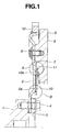
- FIG. 1 is a sectional view of a flywheel for an internal combustion engine showing an embodiment of the invention.
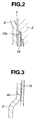
- FIG. 2 is an enlarged view of a part A of FIG. 1.
- FIG. 3 is an enlarged view of a part B of Fig. 1.
- Fig. 4 is a view similar to FIG. 1, but showing another embodiment of the invention.
- FIG. 5 is an enlarged view of a part A of FIG. 4.
- FIG. 6 is an enlarged view of a part B of FIG. 4.
- FIG. 7 is a view similar to FIG. 1, but showing still another embodiment of the invention.
- FIG. 8 is an enlarged view of a part A of FIG. 7.
- FIG. 9 is an enlarged view of a part B of FIG. 7.
- FIG. 1 is a sectional view of a flywheel for an internal combustion engine showing an embodiment of the invention.
- FIG. 2 is an enlarged view of a part A of FIG. 1.
- FIG. 3 is an enlarged view of a part B of FIG. 1.
- a reference numeral 1 denotes a crankshaft of the internal combustion engine.
- a numeral 2 denotes an approximately disk-shaped elastic plate having a flexibility in a bending direction.
- the elastic plate 2 is secured, at its inner circumferential part, to the crankshaft 1 together with a reinforcing plate 3 by attaching bolts 4.
- the elastic plate 2 and the reinforcing plate 3 are attached and fixed to the crankshaft 1 by the attaching bolts 4 passing through the elastic plate 2 and the reinforcing plate 3.
- the reinforcing plate 3 reinforces the fixing portion of the elastic plate 2.
- a reference numeral 5 denotes a mass body secured to the outer circumferential side of the elastic plate 2.
- the mass body 5 is shaped approximately like a ring, and its outer circumferential side is attached and fixed to the outer circumferential side of the elastic plate 2 by attaching bolts 6 passing through the elastic plate 2.
- the mass body 5 contacts with the elastic plate 2 only at its fixing portion to the elastic plate 2, and between the remaining portion and the elastic plate 2, there is formed a predefined axial gap 7.
- a reference numeral 10 denotes a spring member.
- the spring member 10 is disposed in the axial gap 7 between the elastic plate 2 and the mass body 5, and both sides touch the elastic plate 2 and the mass body 5, respectively.
- the spring member 10 in this embodiment is comprised of a disc spring shaped like a truncated cone. The outer circumference of the spring member 10 is held in place by a positioning step 11 formed in the mass body 5, and hence the spring member 10 is positioned in the radial direction.
- At least one of the contact surfaces is curved. Namely, in the contact portion between the spring member 10 and the elastic plate 2, the contact surface 2a of the elastic plate 2 is curved. (See FIG. 3.) In the contact portion between the spring member 10 and the mass body 5, the contact surface 10a of the spring member 10 is curved. (See FIG. 2.)
- the elastic plate 2 is a plate formed by pressing, and the contact surface 10a of the elastic plate 10 is formed in a curved surface at the time of the press forming.
- the spring member 10 is comprised of a press-formed disc spring shaped like a truncated cone, and the contact surface 10a of the disc spring (spring member 10) is shaped into a curved surface at the time of the press forming.
- a ring gear 12 is fixed by welding.
- the elastic plate 2 and the spring member 10 change the natural bending frequency of the crankshaft system out of the normal service range as well as absorb the bending vibration.
- each end portion of the spring member 10 causes friction at the contact portion with the elastic plate 2 or the mass body 5, and thereby acts to achieve the frictional damping effect against the bending vibration.
- the contact surface 2a of the elastic plate 2 is curved in the contact portion between the spring member 10 and the elastic plate 2.
- the contact surface 10a of the spring member 10 is curved.
- the spring member 10 deflects between the elastic plate 2 and the mass body 5, and acts to produce the frictional damping effect against the bending vibration with friction produced by the end portions of the spring member 10 at the contact portions with the elastic plate 2 and the mass body 5, the contact is smooth because of the curvature of the contact surfaces 2a and 10a. Therefore, it is possible to obtain the stable damping effect by the contact of the spring member 10 with the elastic plate 2 and the friction with the mass body 5, and to prevent local wear advantageously in the contact portions.
- the spring member 10 is formed from a press-formed disc spring shaped like a truncated cone, and the contact surface 10a of the disc spring (spring member 10) is formed into a curved surface at the time of the press forming. Therefore, the curved contact surface 10a can be obtained without any special process step.
- the elastic plate 2 is formed by press forming and its contact surface 2a is curved at the time of the press forming. Therefore, the curved contact surface 2a can be formed without any special process step.
- the outer circumference of the spring member 10 is held in place by the positioning step 11 formed in the mass body 5, so it is easy to place the spring member 10 at the correct position and it is possible to prevent the spring member 10 from moving in the radial direction.
- FIGS. 4 to 9 are views for showing different embodiments of the present invention. These embodiments are different from the preceding embodiment in that an axial gap 14 is formed between the reinforcing plate 3 and the mass body 5, and there is disposed, in this gap 14, the spring member 10 with both ends, respectively, contacting with the reinforcing plate 3 and the mass body 5.
- the following is explanation on these embodiment. In the explanation, the same reference numerals are given to the same components as in the preceding embodiment, and repetitive explanations are omitted.
- the before-mentioned reinforcing plate 3 has a plate-shaped base portion 3a contacting with the inner circumferential part of the elastic plate 2, and an annular flange portion 3b extending from the outer circumference of the base portion 3a in the radial direction.
- the base portion 3a reinforces the inner circumferential fixing portion of the elastic plate 2 fixed to the crankshaft 1, and the annular flange portion 3b is so arranged that the spring member 10 contacts with the annular flange 3b.
- the spring member 10 is disposed in the axial gap 14 between the reinforcing plate 3 and the mass body 5. To be precise, it is disposed between the annular flange 3b formed in the reinforcing plate 3 and the mass body 5, and both end sides contact with the reinforcing plate 3 and the mass body 5. The spring member 10 is positioned in the radial direction with the inner circumference of the spring member 10 held in place by the positioning step 15.
- At least one of the contact surfaces is curved. That is, in the contact portion between the spring member 10 and the reinforcing plate 3, the contact surface 10b of the spring member 10 is curved. (See FIG. 6.) In the contact portion between the spring member 10 and the mass body 5, the contact surface 5a of the mass body 5 is curved. (See FIG. 5.)
- the mass body 5 is machined, and the contact surface 5a of the mass body 5 is formed in a curved surface at the timing of the machining.
- the elastic plate 2 and the spring member 10 change the natural bending frequency of the crankshaft system out of the normal range, and absorb the bending vibration.
- each end portion of the spring member 10 causes friction at the contact portion with the reinforcing plate 3 or the mass body 5, and thereby acts to achieve the frictional damping effect against the bending vibration.
- At least one of the contact surfaces is curved.
- the contact surface 10b of the spring member 10 is curved.
- the contact surface 5a of the mass body 10 is curved.
- the spring member 10 deflects between the elastic plate 2 and the mass body 5, and acts to produce the frictional damping effect against the bending vibration with friction produced by the end portions of the spring member 10 at the contact portions with the reinforcing plate 3 and the mass body 5, the contact is smooth because of the curvature of the contact surfaces 5a and 10b. Therefore, it is possible to obtain the stable damping effect by the contact of the spring member 10 with the reinforcing plate 3 and the friction with the mass body 5, and to prevent local wear advantageously in the contact portions.
- the spring member 10 Since the spring member 10 is disposed in contact with the reinforcing plate 3 and the mass body 10, there is formed, between the spring member 10 and the elastic plate 2, a relatively broad space, which can serve to improve the cooling effect of the spring member 10.
- the inner circumference of the spring member 10 is held in place by the positioning step 15 formed in the reinforcing plate 3, so it is easy to place the spring member 10 at the correct position and it is possible to prevent the spring member 10 from moving in the radial direction.
- the spring member 10 is disposed between the flange 3b formed in the reinforcing plate 3 extending in the outer radial direction and the mass body 5, and the spring member is positioned in the radial direction with the outer circumference being held in place by the positioning step 11 formed in the mass body 5.
- the reinforcing plate 3 is formed by press forming, and the contact surface 3c of the reinforcing plate 3 is formed into a curved surface at the time of the press forming.
- the elastic plate 2 and the spring member 10 change the natural bending frequency of the crankshaft system out of the normal range, and absorb the bending vibration.
- each end portion of the spring member 10 causes friction at the contact portion with the reinforcing plate 3 or the mass body 5, and thereby acts to achieve the frictional damping effect against the bending vibration.
- the contact surface 3c of the reinforcing plate 3 is curved in the contact portion between the spring member 10 and the reinforcing plate 3.
- the contact surface 10a of the spring member 10 is curved.
- the spring member 10 deflects between the reinforcing plate 3 and the mass body 5, and acts to produce the frictional damping effect against the bending vibration with friction produced by the end portions of the spring member 10 at the contact portions with the reinforcing plate 3 and the mass body 5, the contact is smooth because of the curvature of the contact surfaces 3c and 10a. Therefore, it is possible to obtain the stable damping effect by the contact of the spring member 10 with the reinforcing plate 3 and the friction with the mass body 5, and to prevent local wear advantageously in the contact portions.
- the reinforcing plate 3 is formed by press forming, and the contact surface 3c of the reinforcing plate 3 is formed into a curved surface at the time of the press forming. Therefore, the curved contact surface 3c can be obtained without any special process step.
- the spring member 10 is disposed in contact with the reinforcing plate 3 and the mass body 5, there is formed, between the spring member 10 and the elastic plate 2, a relatively broad space, which serves to improve the cooling effect of the spring member 10.
- the outer circumference of the spring member 10 is held in place by the positioning step 11 formed in the mass body 5, so it is easy to place the spring member 10 at the correct position and it is possible to prevent the spring member 10 from moving in the radial direction.
Landscapes
- Engineering & Computer Science (AREA)
- General Engineering & Computer Science (AREA)
- Physics & Mathematics (AREA)
- Acoustics & Sound (AREA)
- Aviation & Aerospace Engineering (AREA)
- Mechanical Engineering (AREA)
- Manufacturing & Machinery (AREA)
- Shafts, Cranks, Connecting Bars, And Related Bearings (AREA)
Abstract
Description
Claims (6)
- In a flywheel for an internal combustion engine, provided with an approximately disc-shaped elastic plate that is fixed, at an inner circumferential part, to a crankshaft, and that has a flexibility in a bending direction, and a mass body fixed to an outer circumferential part of the elastic plate,a flywheel for an internal combustion engine characterizedin that, between the elastic plate in a part on a radial outward side of a fixing position to the crankshaft and the mass body, there is provided an axial gap in an axial direction,in that there is disposed, in the gap, a spring member with both end sides contacting, respectively, with the elastic plate and the mass body, andin that, in either or both of a contact portion at which the spring member and the elastic plate contact with each other and a contact portion at which the spring member and the mass body contact with each other, either or both of contact surfaces is curved.
- The flywheel for an internal combustion engine as recited in Claim 1, characterized in that the spring member is comprised of a press formed disc spring shaped in the shape of a truncated cone, and a contact surface of the disc spring is formed into a curved shape at the time of press forming.
- The flywheel for an internal combustion engine as recited in Claim 1, characterized in that the elastic plate is press formed, and a contact surface of the elastic plate is formed into a curved shape at the time of press forming.
- In a flywheel for an internal combustion engine, provided with an approximately disc-shaped elastic plate that is fixed, at an inner circumferential part, to a crankshaft together with a reinforcing plate, and that has a flexibility in a bending direction, and a mass body fixed to an outer circumferential part of the elastic plate,a flywheel for an internal combustion engine characterizedin that, between the reinforcing plate in a part on a radial outward side of a fixing position to the crankshaft and the mass body, there is provided an axial gap in an axial direction,in that there is disposed, in the gap, a spring member with both end sides contacting, respectively, with the reinforcing plate and the mass body, andin that, in either or both of a contact portion at which the spring member and the reinforcing plate contact with each other and a contact portion at which the spring member and the mass body contact with each other, either or both of contact surfaces is curved.
- The flywheel for an internal combustion engine as recited in Claim 4, characterized in that the spring member is comprised of a press formed disc spring shaped in the shape of a truncated cone, and a contact surface of the disc spring is formed into a curved shape at the time of press forming.
- The flywheel for an internal combustion engine as recited in Claim 4, characterized in that the reinforcing plate is press formed, and a contact surface of the reinforcing plate is formed into a curved shape at the time of press forming.
Applications Claiming Priority (3)
| Application Number | Priority Date | Filing Date | Title |
|---|---|---|---|
| JP11784299 | 1999-04-26 | ||
| JP11117842A JP2000310289A (en) | 1999-04-26 | 1999-04-26 | Internal combustion engine flywheel |
| PCT/JP2000/001407 WO2000065249A1 (en) | 1999-04-26 | 2000-03-09 | Flywheel of internal combustion engine |
Publications (3)
| Publication Number | Publication Date |
|---|---|
| EP1099877A1 true EP1099877A1 (en) | 2001-05-16 |
| EP1099877A4 EP1099877A4 (en) | 2005-09-21 |
| EP1099877B1 EP1099877B1 (en) | 2007-05-30 |
Family
ID=14721627
Family Applications (1)
| Application Number | Title | Priority Date | Filing Date |
|---|---|---|---|
| EP00907950A Expired - Lifetime EP1099877B1 (en) | 1999-04-26 | 2000-03-09 | Flywheel of internal combustion engine |
Country Status (4)
| Country | Link |
|---|---|
| EP (1) | EP1099877B1 (en) |
| JP (1) | JP2000310289A (en) |
| DE (1) | DE60035015T2 (en) |
| WO (1) | WO2000065249A1 (en) |
Cited By (1)
| Publication number | Priority date | Publication date | Assignee | Title |
|---|---|---|---|---|
| EP1431610A1 (en) * | 2002-12-19 | 2004-06-23 | LuK Lamellen und Kupplungsbau Beteiligungs KG | Volant d'inertie |
Families Citing this family (4)
| Publication number | Priority date | Publication date | Assignee | Title |
|---|---|---|---|---|
| JP2007162792A (en) * | 2005-12-13 | 2007-06-28 | Valeo Unisia Transmission Kk | Flexible flywheel device |
| JP6478681B2 (en) * | 2015-02-12 | 2019-03-06 | ヴァレオカペックジャパン株式会社 | Flexible flywheel device |
| CN109083979A (en) * | 2018-08-28 | 2018-12-25 | 中国北方发动机研究所(天津) | A kind of flexibility sectional flywheel |
| JP2022114638A (en) * | 2021-01-27 | 2022-08-08 | ヴァレオ、カペック、カンパニー、リミテッド | Flywheel device for hybrid vehicle drive system |
Family Cites Families (9)
| Publication number | Priority date | Publication date | Assignee | Title |
|---|---|---|---|---|
| BE490570A (en) * | 1948-09-01 | |||
| DE3415925A1 (en) * | 1984-04-28 | 1985-10-31 | Fichtel & Sachs Ag, 8720 Schweinfurt | PLATE OR DIAPHRAGM SPRING |
| JPH0620925Y2 (en) * | 1987-02-20 | 1994-06-01 | 日産自動車株式会社 | Flywheel device for internal combustion engine |
| JPH0547314Y2 (en) * | 1987-10-27 | 1993-12-13 | ||
| EP0385752B1 (en) * | 1989-02-28 | 1994-09-21 | Unisia Jecs Corporation | Flywheel assembly for internal combustion engine |
| JP3925954B2 (en) | 1996-02-09 | 2007-06-06 | 株式会社エクセディ | Flywheel assembly |
| FR2762060B1 (en) * | 1997-03-25 | 1999-05-14 | Valeo | FRICTION CLUTCH WITH WEAR RETRACTING DEVICE, ESPECIALLY FOR A MOTOR VEHICLE |
| KR100390092B1 (en) * | 1997-09-04 | 2003-09-19 | 다이하쓰고교가부시키가이샤 | Flexible flywheel |
| JP3318516B2 (en) * | 1997-09-04 | 2002-08-26 | ダイハツ工業株式会社 | Flexible flywheel |
-
1999
- 1999-04-26 JP JP11117842A patent/JP2000310289A/en active Pending
-
2000
- 2000-03-09 WO PCT/JP2000/001407 patent/WO2000065249A1/en not_active Ceased
- 2000-03-09 DE DE60035015T patent/DE60035015T2/en not_active Expired - Lifetime
- 2000-03-09 EP EP00907950A patent/EP1099877B1/en not_active Expired - Lifetime
Cited By (1)
| Publication number | Priority date | Publication date | Assignee | Title |
|---|---|---|---|---|
| EP1431610A1 (en) * | 2002-12-19 | 2004-06-23 | LuK Lamellen und Kupplungsbau Beteiligungs KG | Volant d'inertie |
Also Published As
| Publication number | Publication date |
|---|---|
| DE60035015T2 (en) | 2008-01-24 |
| EP1099877B1 (en) | 2007-05-30 |
| DE60035015D1 (en) | 2007-07-12 |
| JP2000310289A (en) | 2000-11-07 |
| EP1099877A4 (en) | 2005-09-21 |
| WO2000065249A1 (en) | 2000-11-02 |
Similar Documents
| Publication | Publication Date | Title |
|---|---|---|
| EP0903511B1 (en) | Flex plate and flywheel configuration | |
| JP3624020B2 (en) | Torque transmission device cooperating with friction clutch | |
| EP0294856A2 (en) | Torque variation absorbing device | |
| JP3502549B2 (en) | Flywheel of internal combustion engine | |
| US6119549A (en) | Flywheel assembly and a torque converter | |
| US5884743A (en) | Clutch plate with centering feature | |
| EP0308829A2 (en) | Torque variation absorbing device | |
| EP1099877B1 (en) | Flywheel of internal combustion engine | |
| US6276505B1 (en) | Multi-disk clutch | |
| JP4625791B2 (en) | Spring seat and spring assembly | |
| JPH1151119A (en) | Flywheel assembly | |
| JPH09166158A (en) | Clutch disc for automobile friction clutch | |
| JP2007533930A (en) | Power transmission device with corrugated retaining ring | |
| US5950791A (en) | Damper disk assembly | |
| JP3588182B2 (en) | Flywheel assembly | |
| JPH0640997Y2 (en) | Flywheel with dynamic damper | |
| JPH06159438A (en) | Holding flange | |
| JPH0724693Y2 (en) | Flywheel mounting structure | |
| JPH0714250U (en) | Flywheel | |
| KR100390092B1 (en) | Flexible flywheel | |
| JP3569521B2 (en) | Vibration damping device | |
| JPH09217791A (en) | Flywheel assembly | |
| EP0304577A1 (en) | Torque variation absorbing device | |
| JPH0663956U (en) | Flywheel assembly | |
| JP3415804B2 (en) | Flywheel assembly |
Legal Events
| Date | Code | Title | Description |
|---|---|---|---|
| PUAI | Public reference made under article 153(3) epc to a published international application that has entered the european phase |
Free format text: ORIGINAL CODE: 0009012 |
|
| 17P | Request for examination filed |
Effective date: 20001025 |
|
| AK | Designated contracting states |
Kind code of ref document: A1 Designated state(s): AT BE CH CY DE DK ES FI FR GB GR IE IT LI LU MC NL PT SE |
|
| RBV | Designated contracting states (corrected) |
Designated state(s): DE FR GB |
|
| A4 | Supplementary search report drawn up and despatched |
Effective date: 20050809 |
|
| RIC1 | Information provided on ipc code assigned before grant |
Ipc: 7F 16F 15/12 B Ipc: 7F 16F 15/30 A Ipc: 7F 16F 15/315 B |
|
| GRAP | Despatch of communication of intention to grant a patent |
Free format text: ORIGINAL CODE: EPIDOSNIGR1 |
|
| GRAS | Grant fee paid |
Free format text: ORIGINAL CODE: EPIDOSNIGR3 |
|
| GRAA | (expected) grant |
Free format text: ORIGINAL CODE: 0009210 |
|
| AK | Designated contracting states |
Kind code of ref document: B1 Designated state(s): DE FR GB |
|
| REG | Reference to a national code |
Ref country code: GB Ref legal event code: FG4D |
|
| REF | Corresponds to: |
Ref document number: 60035015 Country of ref document: DE Date of ref document: 20070712 Kind code of ref document: P |
|
| ET | Fr: translation filed | ||
| PLBE | No opposition filed within time limit |
Free format text: ORIGINAL CODE: 0009261 |
|
| STAA | Information on the status of an ep patent application or granted ep patent |
Free format text: STATUS: NO OPPOSITION FILED WITHIN TIME LIMIT |
|
| 26N | No opposition filed |
Effective date: 20080303 |
|
| REG | Reference to a national code |
Ref country code: FR Ref legal event code: PLFP Year of fee payment: 17 |
|
| REG | Reference to a national code |
Ref country code: FR Ref legal event code: PLFP Year of fee payment: 18 |
|
| REG | Reference to a national code |
Ref country code: FR Ref legal event code: PLFP Year of fee payment: 19 |
|
| PGFP | Annual fee paid to national office [announced via postgrant information from national office to epo] |
Ref country code: FR Payment date: 20190326 Year of fee payment: 20 Ref country code: GB Payment date: 20190325 Year of fee payment: 20 |
|
| PGFP | Annual fee paid to national office [announced via postgrant information from national office to epo] |
Ref country code: DE Payment date: 20190329 Year of fee payment: 20 |
|
| REG | Reference to a national code |
Ref country code: DE Ref legal event code: R071 Ref document number: 60035015 Country of ref document: DE |
|
| REG | Reference to a national code |
Ref country code: GB Ref legal event code: PE20 Expiry date: 20200308 |
|
| PG25 | Lapsed in a contracting state [announced via postgrant information from national office to epo] |
Ref country code: GB Free format text: LAPSE BECAUSE OF EXPIRATION OF PROTECTION Effective date: 20200308 |