EP1099316B1 - Method and device for the antenna selection in a digital telecommunication system - Google Patents
Method and device for the antenna selection in a digital telecommunication system Download PDFInfo
- Publication number
- EP1099316B1 EP1099316B1 EP99941462A EP99941462A EP1099316B1 EP 1099316 B1 EP1099316 B1 EP 1099316B1 EP 99941462 A EP99941462 A EP 99941462A EP 99941462 A EP99941462 A EP 99941462A EP 1099316 B1 EP1099316 B1 EP 1099316B1
- Authority
- EP
- European Patent Office
- Prior art keywords
- antennas
- antenna
- rfp
- correlation
- time
- Prior art date
- Legal status (The legal status is an assumption and is not a legal conclusion. Google has not performed a legal analysis and makes no representation as to the accuracy of the status listed.)
- Expired - Lifetime
Links
- 238000000034 method Methods 0.000 title claims description 34
- 238000005259 measurement Methods 0.000 claims description 16
- 230000009977 dual effect Effects 0.000 claims description 2
- 238000012795 verification Methods 0.000 claims 3
- FGUUSXIOTUKUDN-IBGZPJMESA-N C1(=CC=CC=C1)N1C2=C(NC([C@H](C1)NC=1OC(=NN=1)C1=CC=CC=C1)=O)C=CC=C2 Chemical compound C1(=CC=CC=C1)N1C2=C(NC([C@H](C1)NC=1OC(=NN=1)C1=CC=CC=C1)=O)C=CC=C2 FGUUSXIOTUKUDN-IBGZPJMESA-N 0.000 claims 2
- 238000012508 change request Methods 0.000 claims 1
- 238000005562 fading Methods 0.000 description 6
- 241001124569 Lycaenidae Species 0.000 description 3
- 235000014987 copper Nutrition 0.000 description 3
- 238000006243 chemical reaction Methods 0.000 description 2
- 238000004904 shortening Methods 0.000 description 2
- AYFVYJQAPQTCCC-GBXIJSLDSA-N L-threonine Chemical compound C[C@@H](O)[C@H](N)C(O)=O AYFVYJQAPQTCCC-GBXIJSLDSA-N 0.000 description 1
- 230000003044 adaptive effect Effects 0.000 description 1
- 230000005540 biological transmission Effects 0.000 description 1
- 238000012790 confirmation Methods 0.000 description 1
- 230000002596 correlated effect Effects 0.000 description 1
- 230000001066 destructive effect Effects 0.000 description 1
- 238000001514 detection method Methods 0.000 description 1
- 238000010586 diagram Methods 0.000 description 1
- 230000000694 effects Effects 0.000 description 1
- 230000005672 electromagnetic field Effects 0.000 description 1
- 238000005516 engineering process Methods 0.000 description 1
- 238000009434 installation Methods 0.000 description 1
- 230000005855 radiation Effects 0.000 description 1
- 238000011160 research Methods 0.000 description 1
- 238000010187 selection method Methods 0.000 description 1
- 230000011664 signaling Effects 0.000 description 1
- 230000001360 synchronised effect Effects 0.000 description 1
- 230000001755 vocal effect Effects 0.000 description 1
Images


Classifications
-
- H—ELECTRICITY
- H04—ELECTRIC COMMUNICATION TECHNIQUE
- H04B—TRANSMISSION
- H04B7/00—Radio transmission systems, i.e. using radiation field
- H04B7/02—Diversity systems; Multi-antenna system, i.e. transmission or reception using multiple antennas
- H04B7/04—Diversity systems; Multi-antenna system, i.e. transmission or reception using multiple antennas using two or more spaced independent antennas
- H04B7/08—Diversity systems; Multi-antenna system, i.e. transmission or reception using multiple antennas using two or more spaced independent antennas at the receiving station
- H04B7/0802—Diversity systems; Multi-antenna system, i.e. transmission or reception using multiple antennas using two or more spaced independent antennas at the receiving station using antenna selection
- H04B7/0805—Diversity systems; Multi-antenna system, i.e. transmission or reception using multiple antennas using two or more spaced independent antennas at the receiving station using antenna selection with single receiver and antenna switching
- H04B7/0808—Diversity systems; Multi-antenna system, i.e. transmission or reception using multiple antennas using two or more spaced independent antennas at the receiving station using antenna selection with single receiver and antenna switching comparing all antennas before reception
-
- H—ELECTRICITY
- H04—ELECTRIC COMMUNICATION TECHNIQUE
- H04W—WIRELESS COMMUNICATION NETWORKS
- H04W36/00—Hand-off or reselection arrangements
- H04W36/24—Reselection being triggered by specific parameters
- H04W36/30—Reselection being triggered by specific parameters by measured or perceived connection quality data
- H04W36/302—Reselection being triggered by specific parameters by measured or perceived connection quality data due to low signal strength
Definitions
- the present invention relates to digital telecommunication systems according to Time Division Multiple Access (TDMA), and in particular, but not exclusively, relates to systems operating according the DECT standard (Digital Enhanced Cordless Telecommunications).
- TDMA Time Division Multiple Access
- DECT Digital Enhanced Cordless Telecommunications
- the present invention relates to a method and a device for the selection of an antenna used in the fixed radio station of such system.
- a DECT system without that this should be limited thereto.
- the invention can be generally applied in systems where the connection between two transceiver units (a radiomobile or portable unit or PP (Portable Part according to the DECT terminology) and a fixed radio station or RFP (Radio Fixed Part) is realized.
- PP Radiomobile or portable unit
- RFP Radio Fixed Part
- the DECT system includes a plurality of fixed radio stations distributed in a way to cover the interested areas and controlled by a centralised unit (CCFP, Central Control Fixed Part), and connected to a switching network which may be the public one of the private type (PABX), and of portable units linking up via radio with the fixed radio stations, and being able to communicate with each other and with others fixed users connected to the telephone network.
- the links may be of the voice type or they may enable the exchange of data occupying the equivalent of one or more voice "channels".
- RFP Radio Fixed Part
- Dl drop/insert devices
- Each RFP can manage via radio a certain number of PPs, which generally are mobile.
- the coppers end up at a TRAnScoder unit TRAS, and the latter is for example connected to the public network PSTN (Public Switching Telephone Network) through a Central Control Fixed Part (CCFP) associated to a switching network or a dedicaded switching module MEP.
- PSTN Public Switching Telephone Network
- CCFP Central Control Fixed Part
- digital 64 Kbit/s channels typically set up the interface between the CCFP and the accessed network.
- a set of transcoders TRAS is associated providing for the conversion of the PCM codification (Pulse Code Modulation) on 8 bits used at the PSTN side into an ADPCM (Adaptive Differential Pulse Code Modulation) codification on four bits used at the DECT side.
- PCM Physical Coding Modulation
- ADPCM Adaptive Differential Pulse Code Modulation
- the 2,048 Mbit/s (bi-directional) connection link connecting the CCFP to the different RFPs supports therefore 48 voice channels plus a predetermined number of synchronisation and signalling channels.
- the area covered by a fixed radio station or cell is generally rather reduced, arriving also to a radio coverage radius of tens or hundreds of metres.
- Typical applications of the personal telephony systems can be found in industrial plants where they may substitute the installation of a cabled network, in shopping centres or urban centres where they may advantageously substitute public telephone boxes and so on.
- the telecommunication network for personal telephony is of the digital type.
- the radio access technology is of the type FDMA (Frequency Division Multiple Access) - TDMA (Time Division Multiple Access) - TDD (Time Division Duplex).
- the system is of the TDD type as the transmission and reception direction are time divided. More precisely, as illustrated with reference to Fig. 2, the time frame interval of 10 milliseconds is divided into two halves: usually during the first 5 ms (i.e. in the first half frame) the fixed radio station transmits and the portables receive, and in the following 5 ms (i.e. in the second half frame) the contrary happens.
- Each half frame is set up by 12 time channels or time slots, hereafter for the sake of brevity also referred to as "slot", (from which it comes that DECT is a TDMA system, set up by 420 (or in some cases by 424) bits.
- the slots are transmitted or received using 10 (or more) different frequencies (from where it results that DECT is an FDMA system as well, which allows to provide to the system up to 120 (or more) radio channels (where a radio channel is identified by the pair (time slot + frequency).
- the DECT multiframe is illustrated in Fig.3 and has a duration of 160 ms, so that it includes 16 frames of 10 msec each as described in Fig. 2.
- the fixed radio station or RFP has an antenna system which may have different configurations:
- the RFP includes a selection device or appliance among the antennas enabling the selection of the most suitable one that is that antenna which assures the better quality for the detected signal.
- the transmitted signal may be affected by the so-called fading phenomenon constituted by amplitude and phase variations of the electromagnetic field or of the power of the detected signal due to changeable propagation conditions. Because of such a phenomenon, in a predetermined instant the signal can be received with major intensity from a predetermined antenna (or from a predetermined first group of antennas) while in a following instant this signal can be received with major intensity from a second antenna (or from another predetermined second group of antennas).
- the antenna selection appliance is able to manage an antenna switching according to two or more methods.
- the switching may occur based on a switching method, called “time switch diversity” or it can be based on a switching method called “instant diversity”.
- the switching method "time switch diversity” is based on the concept for which, in case the reception of a signal from an antenna (or antenna group) has to be considered failed (according to a preset failure criterion), then in the next received frame a different antenna (or antenna group) is selected at the RFP (see also Fig. 2).
- the predetermined failure criterion may be of the proprietary type and could be based for example on the estimation of the received field strength or RSSI (Received Signal Strength Indicator) or, more generally on the estimation of the perceived signal quality.
- the "instant diversity” switching method has the advantage compared to “Time switch diversity” method that makes it possible to understand during the first 10 ⁇ s which is the best antenna and which will be selected to detect the remaining part of the signal.
- the "instant diversity" method presents certain critical aspects from the implementation point of view, because such operations are carried out at the beginning of the slot, sacrificing a few of those bits (i.e. the preamble bits) useful for the timing reconstruction and which do not bring any user data.
- the antenna switching introduces a discontinuity in the demodulation of the slot which would make lose part of its informative content.
- the object of the present invention is to overcome the above-mentioned problems and limitations, and in particular to propose a better method and a device for the selection of the most suitable antenna.
- the method according to the invention allows also obtaining an estimation of the speed of the mobile user.
- the present invention achieves these objects by means of a method with the features listed in claim 1 and by means of a device having the features listed in claim 10.
- the DECT standard presents an organised frame, so that the receiver, at the moment of receiving a useful signal from one radio channel, has to:
- Some of these operations may fail, because of the different factors influencing the propagation such as link budget, selective fading, Doppler effect, etc.
- the method according to the invention foresees that in the case of missed correlation all available antennas will be scanned sequentially carrying out a certain number K of cycles.
- K (420 * 868000 - X - Y) / (N*Ta+(N-1)*TC) where:
- antenna(s) selection More precisely, it will be selected that antenna which turns out to be the best regarding the detected RSSI (i.e. which shows the major and stable RSSI value).
- step 1 If the answer to step 1 is negative, that is if the power variability of each antenna during the period of a slot is high, then at
- a further advantage of this improvement consists in the fact that the extracted information is much more significant and efficient the more critical the situation of the channel and therefore the number of lost bursts are. However nothing prohibits, in the case of finding possible anomalies, to extend these measurements outside of the lost bursts, sacrificing some correctly detected bursts or using other techniques to save the situation.
Landscapes
- Engineering & Computer Science (AREA)
- Computer Networks & Wireless Communication (AREA)
- Signal Processing (AREA)
- Mobile Radio Communication Systems (AREA)
- Input Circuits Of Receivers And Coupling Of Receivers And Audio Equipment (AREA)
Description
- The present invention relates to digital telecommunication systems according to Time Division Multiple Access (TDMA), and in particular, but not exclusively, relates to systems operating according the DECT standard (Digital Enhanced Cordless Telecommunications).
- More precisely, the present invention relates to a method and a device for the selection of an antenna used in the fixed radio station of such system.
In the following description reference will be made in particular to a DECT system, without that this should be limited thereto. The invention can be generally applied in systems where the connection between two transceiver units (a radiomobile or portable unit or PP (Portable Part according to the DECT terminology) and a fixed radio station or RFP (Radio Fixed Part) is realized.
As already known, the DECT system includes a plurality of fixed radio stations distributed in a way to cover the interested areas and controlled by a centralised unit (CCFP, Central Control Fixed Part), and connected to a switching network which may be the public one of the private type (PABX), and of portable units linking up via radio with the fixed radio stations, and being able to communicate with each other and with others fixed users connected to the telephone network. The links may be of the voice type or they may enable the exchange of data occupying the equivalent of one or more voice "channels".
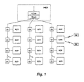
At first, an exemplary DECT network architecture is schematically illustrated in Fig. 1. - It comprises groupings of h (in the example of the figure h = 4) fixed radio stations RFP (Radio Fixed Part) preferably connected to coppers (in the example 3 coppers) set up by connection or dorsal lines L through drop/insert devices Dl. Without departing from the scope of the present invention, it turns obviously out to be possible to connect in a star-shaped way each RFP to the CCFP eliminating the aforesaid connection lines, and therefore obviously also the Drop/Insert devices DI.
- Each RFP can manage via radio a certain number of PPs, which generally are mobile.
The coppers end up at a TRAnScoder unit TRAS, and the latter is for example connected to the public network PSTN (Public Switching Telephone Network) through a Central Control Fixed Part (CCFP) associated to a switching network or a dedicaded switching module MEP.
Regarding the vocal signals, digital 64 Kbit/s channels typically set up the interface between the CCFP and the accessed network. To the CCFP unit a set of transcoders TRAS is associated providing for the conversion of the PCM codification (Pulse Code Modulation) on 8 bits used at the PSTN side into an ADPCM (Adaptive Differential Pulse Code Modulation) codification on four bits used at the DECT side. In this way two 32 Kbit/s channels can be mapped onto each 64 Kbit/s channel. - The 2,048 Mbit/s (bi-directional) connection link connecting the CCFP to the different RFPs supports therefore 48 voice channels plus a predetermined number of synchronisation and signalling channels.
The area covered by a fixed radio station or cell is generally rather reduced, arriving also to a radio coverage radius of tens or hundreds of metres. Typical applications of the personal telephony systems can be found in industrial plants where they may substitute the installation of a cabled network, in shopping centres or urban centres where they may advantageously substitute public telephone boxes and so on. - The telecommunication network for personal telephony is of the digital type. The radio access technology is of the type FDMA (Frequency Division Multiple Access) - TDMA (Time Division Multiple Access) - TDD (Time Division Duplex).
- The system is of the TDD type as the transmission and reception direction are time divided. More precisely, as illustrated with reference to Fig. 2, the time frame interval of 10 milliseconds is divided into two halves: usually during the first 5 ms (i.e. in the first half frame) the fixed radio station transmits and the portables receive, and in the following 5 ms (i.e. in the second half frame) the contrary happens. Each half frame is set up by 12 time channels or time slots, hereafter for the sake of brevity also referred to as "slot", (from which it comes that DECT is a TDMA system, set up by 420 (or in some cases by 424) bits. The slots are transmitted or received using 10 (or more) different frequencies (from where it results that DECT is an FDMA system as well, which allows to provide to the system up to 120 (or more) radio channels (where a radio channel is identified by the pair (time slot + frequency).
- The DECT multiframe is illustrated in Fig.3 and has a duration of 160 ms, so that it includes 16 frames of 10 msec each as described in Fig. 2.
- For further details on the DECT system please refer to the specifications established by the European Telecommunications Standards Institute, briefly ETSI (Ref. EN 300 175 specification).
- In a DECT system the fixed radio station or RFP has an antenna system which may have different configurations:
- N antennas (with N equal to at least 2) for management in space diversity and/or polarisation of the received signal;
- a set of sectorial antennas, that is a system in which a plurality of antennas is connected to each RFP where every antenna of the set lightens just a portion (or sector) of the entire cell or of the RFP coverage area (usually trisection antennas are defined which implies therefore the use of antennas with a coverage angle of 120°);
- a set of phased antennas suitable to set up a radiation diagram with variable direction and gain.
- Moreover the RFP includes a selection device or appliance among the antennas enabling the selection of the most suitable one that is that antenna which assures the better quality for the detected signal.
- In fact the transmitted signal, especially in an urban environment, may be affected by the so-called fading phenomenon constituted by amplitude and phase variations of the electromagnetic field or of the power of the detected signal due to changeable propagation conditions. Because of such a phenomenon, in a predetermined instant the signal can be received with major intensity from a predetermined antenna (or from a predetermined first group of antennas) while in a following instant this signal can be received with major intensity from a second antenna (or from another predetermined second group of antennas).
- Therefore mainly due to this phenomenon, it is necessary to choose time by time the antenna (or the antennas group) supplying the best signal.
- According to the known art the antenna selection appliance is able to manage an antenna switching according to two or more methods.
- In particular the switching may occur based on a switching method, called "time switch diversity" or it can be based on a switching method called "instant diversity". The switching method "time switch diversity" is based on the concept for which, in case the reception of a signal from an antenna (or antenna group) has to be considered failed (according to a preset failure criterion), then in the next received frame a different antenna (or antenna group) is selected at the RFP (see also Fig. 2). The predetermined failure criterion may be of the proprietary type and could be based for example on the estimation of the received field strength or RSSI (Received Signal Strength Indicator) or, more generally on the estimation of the perceived signal quality.
- This switching method "time switch diversity" presents the disadvantage that reaction cah be slow in respect to the aforesaid fading phenomenon that should be hindered.
- The already known switching method (see the paper "Implementation of the Preamble Switched Antenna Diversity Option" prepared by Dag Akerberg and distributed by Ericsson to the participants of RES-3R/SEG on 1994-10-17) named "instant diversity" is instead realised by a fast sampler able to carry out an RSSI measurement in a short time period equal to 2-3 µs with the possibility to switch the antenna in a comparable amount of time. For example, always according to the present state of the art it is possible to sample a signal at the beginning of the slot carrying out a measurement on the
antenna 1 for about 3 µs, to change the antenna in a very short time, equal to about 1 - 2 µs and then sample the received signal on the other antenna. - The "instant diversity" switching method has the advantage compared to "Time switch diversity" method that makes it possible to understand during the first 10 µs which is the best antenna and which will be selected to detect the remaining part of the signal.
- However it is necessary to note that the "instant diversity" method presents certain critical aspects from the implementation point of view, because such operations are carried out at the beginning of the slot, sacrificing a few of those bits (i.e. the preamble bits) useful for the timing reconstruction and which do not bring any user data. On the other hand it cannot be carried out during the slot, because the antenna switching introduces a discontinuity in the demodulation of the slot which would make lose part of its informative content.
- There has also been the proposal to use an extended preamble consisting in the repetition, at the beginning of the slot, of the preamble field in order to dedicate the first part of this field to the selection of the antenna and the second part to the specific function for which such a preamble has been foreseen by ETSI standard (like f.i. the timing reconstruction and alignment between the two communicating radio transceivers. However it is necessary to point out that if such a solution to extend preamble field makes it possible to solve the above-mentioned problems, it also defines the turning up of a further drawback consisting in the shortening of the inter slot guard periods, which means major interference among DECT systems which are not synchronised each other (e.g. because they do not refer to the same operator) and the shortening of the propagation range.
A combination of "instant diversity" and preamble-based antenna selection technique is disclosed in the paper "Predetection quality diversity scheme for DECT outdoor applications S. Safavi and L.B. Lopes, ELECTRONICS LETTERS, vol.32, no. 11, 23 May 1996 (1996-05-23), pages 966-968.
This additional antenna selection technique has therefore the drawbacks above mentioned in connection with said instant diversity tecnique and in connection with said extended preamble tecnique.ln the case of a system that foresees sectorial antennas it is also known to carry out the selection of antennas in such array. More precisely, at the moment when the connection on the antenna in use turns out to be degraded, a switching operation can be carried out on other antennas to see if the connection quality improved. - But such solution includes however the drawback that the choice requires to realise an RSSI measuring on a slot for each antenna of the array, and therefore it may last rather a lot of slots; too many bursts could be sacrificed because of having tried some antennas not suitable for this link. Moreover the measurements are heterogeneous with each other as they are carried out at different instants.
- Furthermore it is necessary to point out that, as there is the possibility to carry out an RSSI measurement, methods have been proposed for the estimation of the speed of a mobile user which are based on the received field strength variation. Such finding is important for the handover between a DECT cell and another one of the GSM system when the mobile user moves quickly in relatively small cells.
- The object of the present invention is to overcome the above-mentioned problems and limitations, and in particular to propose a better method and a device for the selection of the most suitable antenna. Advantageously the method according to the invention allows also obtaining an estimation of the speed of the mobile user.
- The present invention achieves these objects by means of a method with the features listed in
claim 1 and by means of a device having the features listed inclaim 10. - Additional features which are belived to be novel are set forth with particularity in the appended claims.
- According to the method of the invention, a series of measurements is carried out during the reception of the useful signal which does not overcome the adopted criterion to define the correlation of the slots and which will be declared as lost (so-called "SYNC FAILURE").
- Now it will be illustrated the SYNC FAILURE concept. The DECT standard presents an organised frame, so that the receiver, at the moment of receiving a useful signal from one radio channel, has to:
- 1. reconstruct first of all the phase timings (bit and slot) from the preamble field (16 + 16 bits),
- 2. and then demodulate the informative content (field A and field B).
-
- Some of these operations may fail, because of the different factors influencing the propagation such as link budget, selective fading, Doppler effect, etc.
- In particular there is a key function for the detection of the transmitted signal (said "Burst") from a radio channel, which can be identified in the correlation operation. Every RFP (and, of course, every PP) is therefore provided with a correlation circuit based on criteria which can be manufactured dependant When the found out correlation value does not overcome these criterions then the received burst is declared lost (SYNC FAILURE).
- According to the previous technique no other operation will be carried out on these lost bursts except the one of counting them as such (WER calculation, Word Error Rate), taking for granted in general, that the content cannot be recovered and that the selected antenna by which they have been received, was the worst one.
- Applying instead the innovative method the present invention is based on, that is executing some measurements on the received bursts having caused the sync failure, it turns out to be possible to achieve the following advantages:
- the measures are not destructive for the useful signal as they are carried out on unusable slots;
- it is possible to carry out in a very short time the measures related to the different antennas so that the selection of the most suitable antenna can be done in due time;
- measures carried out in the lost slots are more significant because they take place together with a criticality in progress that has to be improved and resolved.
- The invention will now be described in a more detailed way with reference to a preferred but not limiting embodiment illustrated with reference to the enclosed drawings, in which:
- Fig. 1, already described, shows the network architecture of a DECT system;
- Fig. 2, already described, shows the frame structure of the illustrated DECT system;
- Fig. 3, already described, shows the multiframe structure of the DECT system;
- Fig. 4 shows a flow chart of the antenna selection method according to the invention.
-
- The method according to the invention foresees that in the case of missed correlation all available antennas will be scanned sequentially carrying out a certain number K of cycles.
- The number K of cycles depends on the minimum duration of the measurement on each single antenna, on the minimum antenna switching time and on the number of available antennas according to the following relation:
- "420" is the number of bits in a time slot
- "868000" is the bit time duration [µS]
- "K" is the number of measurement cycles on the slot
- "N" is the number of antennas
- "Ta" is the measurement time [µS] on the single antenna
- "Tc" is the switching time [µS] among the antennas
- "X" is the inferior limit [µS] of the correlation time window
- "Y" is the superior limit [µS] of the correlation time window
-
- During said scanning period the RSSI values from the different antennas are measured, and therefore for each slot a table of the following type is collected:


- Referring to Fig. 4, the method foresees the following steps:
- Step 1: verify if the power variability of each antenna in the period of one slot is comprised in a preset range, for example ±3 dBm.
- Step 2: in the affirmative case, that is in stationary slot conditions,
step 2 is started off to check if the power variability among the different antennas is comprised in a predetermined range, for example ±3 dBm. -
- In the negative case, according to the type of antenna(s), which has caused such result, the choice is carried out (antenna(s) selection). More precisely, it will be selected that antenna which turns out to be the best regarding the detected RSSI (i.e. which shows the major and stable RSSI value).
- Step 3: In the affirmative case, always at
step 2, at step 3 a counter J(J=J+1) is increased, and at - Step 4: it will be stated, if the J counter value is superior to a fixed threshold (J>Thre.?); in the negative case the table will be reconsidered, while in the positive case at
- Step 5: the table of the channels will be updated, and at
- Step 6: the bearer handover will be required as the diversity does not turn out to be efficient.
-
- If the answer to step 1 is negative, that is if the power variability of each antenna during the period of a slot is high, then at
- Step 7: a counter I will be increased (I=I+1), and at
- Step 8: it will be checked, if the I counter value overcomes a preset threshold (I>Tresh.?): in the negative case the table will be considered again, while in the positive case at
- Step 9: the mode handover will be required to the PP, as this means that the portable set is moving with an appreciable speed compared to the dimensions of the cell and therefore defining frequent handover creates problems to the serving system. For this reason if the PP is of the dual band type, that is able either to operate according to the GSM and the DECT standard, then the PP will be forced to hand-over towards the GSM system, its speed being reasonably compatible with the operating modalities of such a system and incompatible with the operating modalities of the DECT system.
-
- The measures correlated to the innovative method according to the present invention supply therefore the following additional information:
-
- 1) confirmation of the hypothesis that the used antenna is the worst (the hypothesis is based on the fact that the burst has not been received correctly).
- 2) Efficiency of the antenna diversity. In the case the measurements carried out on different antennas are comparable, that is contained in a range of + / - 3 dB) and still the transmitted burst is not correctly detected (i.e. it has been lost) it is preferable not to insist on the use of the diversity, but it is preferable to suggest the PP to carry out a handover.
- 3) The event with similar measurements could be stored as a statistic counter to value the entity of the improvement introduced by the antenna diversity.
-
- A further advantage of this improvement consists in the fact that the extracted information is much more significant and efficient the more critical the situation of the channel and therefore the number of lost bursts are.
However nothing prohibits, in the case of finding possible anomalies, to extend these measurements outside of the lost bursts, sacrificing some correctly detected bursts or using other techniques to save the situation. - During a slot it is possible to value the power received from all antennas of the array, selecting the one with the major received power.
- The advantages in this case are the following:
- 1. the measurements are carried out in a very short time and therefore they provide homogeneous information;
- 2. time consuming researches by attempt are avoided on antennas which reception turns out to be of bad quality;
- 3. estimation of the mobile speed. Regarding the estimation of the speed, this can happen according to two modalities. When the duration of the slot is comparable to the duration of the fading phenomenon, the slot fading conditions can be considered as stationary for the mobile speed below 10-15 [KM] / h.
-
- Although a particular embodiment of the present invention has been described, it should be understood that the present invention is not limited thereto since other embodiments may be made by those skilled in the art without departing from the scope thereof. It is thus contemplated that the present invention encompasses any and all such embodiments covered by the following claims.
But when the duration of the slot is too short compared to the fading phenomenon, the measurement is used as a trigger for other measurements.
Claims (10)
- Method for the antenna selection in the fixed radio station (RFP) of a digital telecommunication system of the TDMA type, in which the signals are arranged in frames with a preset duration, and in each frame a predetermined number of time slots are assigned,
said system including a plurality of radiomobile units (PP), and said fixed radio station (RFP), which at its turn includes correlation means, i.e. means adapted to perform the correlation operation at the moment of receiving of each time slot of the frame of said digital signal and means adapted to select one antenna, or a plurality of antennas, connected to them, and in particular:characterised in that it comprises the following operational steps:N antennas, with N≥1, for the management in space diversity and/or polarisation of the received signal, and/oran array of sectorial antennas, and/oran array of phased antennas,a) verifying if the correlation operation carried out by said correlation means has been successful or not;b) in the case of failed correlation, sequential scanning within the same time slot of all available antennas and repeatedly measuring the received field strength or RSSI for a predetermined number K of measuring cycles;c) compiling a table containing for each antenna K measured RSSI values;d) verifying if the power variability of each antenna during the period of a time slot is included in a first preset range;e) in the affirmative case, verifying if the power variability between the different antennas stays in a second preset range comparing the data contained in the above-mentioned table;f) if the verification according to the previous step e) has a negative result, starting the selection of the antenna/s applying a criterion which takes into consideration the result of the comparison according to the previous step e). - Method according to claim 1, characterised in that said fixed radio station (RFP] includes at least a pair of space diversity antennas and in that the criterion according to step f) consists in the choice of the antenna which received field strength value turns out to be the highest one among all measured ones.
- Method according to claim 1, characterised in that said fixed radio station (RFP) includes at least an array of sectorial antennas, and in that the criterion according to step f) consists in the choice of the antenna, which received field strength value turns out to be the highest one among all measured ones.
- Method according to claim 1, characterised in that, if said verification phase according to step d) does not have an affirmative result, it comprises a further step to verify if such value overcomes a first preset threshold, and if not the cycle of operations will be repeated starting from the above-mentioned step b).
- Method according to claim 4, characterised in that, if the radiomobile unit is of the dual mode type and if said further checking step to verify if said value is higher than said first preset threshold has a positive result, also the operational modality change request of the radiomobile unit will be started off (mode handover).
- Method according to claim 1, characterised by fact that, if said verification phase according to step e) points out an overcoming of said second preset range, a further step is foreseen to verify if the power difference among the different antennas overcomes a second preset threshold, and in the negative case, the cycle of operations will be repeated starting from the above-mentioned step b).
- Method according to claim 6, characterised in that, if said further step to verify if the difference of power among the different antennas overcomes a second preset threshold has a positive result, then also the request to change the bearer in use will be started off (bearer handover).
- Method according to claim 1, characterised in that said number K of measuring cycles is calculated according to the following formula:"420" is the number of bits in a time slot;"868000" is the bit time duration [µS];"N" is the number of antennas;"Ta" is the measurement time [µS] on the single antenna;"Tc" is the switching time [µS] among the antennas;"X" is the inferior limit [µS] of the correlation time window;"Y" is the superior limit [µS] of the correlation time window.
- Method according to the previous claims, characterised in that said first and second preset ranges are equal to ± 3 dBm.
- Device for the antenna selection in the fixed radio station (RFP) of a digital telecommunication system of the TDMA type, in which the signals are arranged in frames with a predetermined duration, and in each frame a predetermined number of time slots will be assigned, said system including a plurality of radiomobile units (PP) and said fixed station (RFP) which at its turn includes means adapted to carry out the correlation operation at the moment of receiving each time slot of the frame of said digital signal and means for the selection of one antenna or of a plurality of antennas to which are connected:characterised in that it comprises means adapted for performing the steps of method of claim 1.N antennas for the management in space diversity and/or polarisation of the received signal, and/oran array of sectorial antennas, and/ora phased array of antennas,
Applications Claiming Priority (3)
| Application Number | Priority Date | Filing Date | Title |
|---|---|---|---|
| ITMI981674 | 1998-07-21 | ||
| IT98MI001674A ITMI981674A1 (en) | 1998-07-21 | 1998-07-21 | METHOD AND DEVICE FOR THE SELECTION OF ANTENNA IN A DIGITAL TELECOMMUNICATION SYSTEM |
| PCT/EP1999/005326 WO2000005827A1 (en) | 1998-07-21 | 1999-07-16 | Method and device for the antenna selection in a digital telecommunication system |
Publications (2)
| Publication Number | Publication Date |
|---|---|
| EP1099316A1 EP1099316A1 (en) | 2001-05-16 |
| EP1099316B1 true EP1099316B1 (en) | 2003-04-23 |
Family
ID=11380478
Family Applications (1)
| Application Number | Title | Priority Date | Filing Date |
|---|---|---|---|
| EP99941462A Expired - Lifetime EP1099316B1 (en) | 1998-07-21 | 1999-07-16 | Method and device for the antenna selection in a digital telecommunication system |
Country Status (5)
| Country | Link |
|---|---|
| EP (1) | EP1099316B1 (en) |
| CA (1) | CA2337510A1 (en) |
| DE (1) | DE69907205T2 (en) |
| IT (1) | ITMI981674A1 (en) |
| WO (1) | WO2000005827A1 (en) |
Cited By (2)
| Publication number | Priority date | Publication date | Assignee | Title |
|---|---|---|---|---|
| US9291684B2 (en) | 2013-06-28 | 2016-03-22 | Rosemount, Inc. | Logic capable power module |
| US9518852B2 (en) | 2012-09-27 | 2016-12-13 | Rosemount Inc. | Hybrid power module with fault detection |
Family Cites Families (2)
| Publication number | Priority date | Publication date | Assignee | Title |
|---|---|---|---|---|
| US5459873A (en) * | 1993-08-21 | 1995-10-17 | Motorola, Inc. | Method and communication system for improved channel scanning and link establishment determinations |
| AU3347495A (en) * | 1994-09-02 | 1996-03-27 | Nokia Telecommunications Oy | A method for improving connection quality in a cellular radio system and a receiver unit |
-
1998
- 1998-07-21 IT IT98MI001674A patent/ITMI981674A1/en unknown
-
1999
- 1999-07-16 CA CA002337510A patent/CA2337510A1/en not_active Abandoned
- 1999-07-16 EP EP99941462A patent/EP1099316B1/en not_active Expired - Lifetime
- 1999-07-16 DE DE69907205T patent/DE69907205T2/en not_active Expired - Fee Related
- 1999-07-16 WO PCT/EP1999/005326 patent/WO2000005827A1/en not_active Ceased
Cited By (2)
| Publication number | Priority date | Publication date | Assignee | Title |
|---|---|---|---|---|
| US9518852B2 (en) | 2012-09-27 | 2016-12-13 | Rosemount Inc. | Hybrid power module with fault detection |
| US9291684B2 (en) | 2013-06-28 | 2016-03-22 | Rosemount, Inc. | Logic capable power module |
Also Published As
| Publication number | Publication date |
|---|---|
| CA2337510A1 (en) | 2000-02-03 |
| DE69907205T2 (en) | 2004-02-05 |
| EP1099316A1 (en) | 2001-05-16 |
| ITMI981674A1 (en) | 2000-01-21 |
| ITMI981674A0 (en) | 1998-07-21 |
| DE69907205D1 (en) | 2003-05-28 |
| WO2000005827A1 (en) | 2000-02-03 |
Similar Documents
| Publication | Publication Date | Title |
|---|---|---|
| EP1044518B1 (en) | An improved antenna diversity switching system for tdma-based telephones | |
| US6308078B1 (en) | Transmission time delay measurement at transmission paths in a radio telecommunication system | |
| JP2002500848A (en) | Transmission time slot timing control method | |
| US6144650A (en) | Mobile communication system | |
| US5459873A (en) | Method and communication system for improved channel scanning and link establishment determinations | |
| EP0761045B1 (en) | A method for improving connection quality in a cellular radio system, and a base station | |
| KR100712035B1 (en) | A gain control method of when cell perform initial searching in a TD-SCDMA mobile communication system | |
| US5825760A (en) | Transmission method and a cellular radio system | |
| CA2267208C (en) | Dual mode portable telephone unit | |
| US6738365B1 (en) | Method of improving connection quality and system capacity, and a cellular radio system | |
| CA2337510A1 (en) | Method and device for the antenna selection in a digital telecommunication system | |
| EP0908023B1 (en) | Communication protocol for spread spectrum wireless communication system | |
| KR100566687B1 (en) | Power Measurement System and Method | |
| US5974321A (en) | Method for selecting a signal, and a cellular radio system | |
| JPH10322267A (en) | Wireless channel control method and system | |
| EP0479741B1 (en) | Method for antenna selection in a mobile radio communication system | |
| WO2001008436A1 (en) | Method and system for measuring during a call set-up procedure | |
| WO2000019752A1 (en) | Method and system to diagnose the functional state of radio base stations in a digital telecommunication system | |
| HK1018557B (en) | Communication protocol for spread spectrum wireless communication system |
Legal Events
| Date | Code | Title | Description |
|---|---|---|---|
| PUAI | Public reference made under article 153(3) epc to a published international application that has entered the european phase |
Free format text: ORIGINAL CODE: 0009012 |
|
| 17P | Request for examination filed |
Effective date: 20010214 |
|
| AK | Designated contracting states |
Kind code of ref document: A1 Designated state(s): AT BE CH CY DE DK ES FI FR GB GR IE IT LI LU MC NL PT SE Kind code of ref document: A1 Designated state(s): DE FI FR IT SE |
|
| GRAH | Despatch of communication of intention to grant a patent |
Free format text: ORIGINAL CODE: EPIDOS IGRA |
|
| GRAH | Despatch of communication of intention to grant a patent |
Free format text: ORIGINAL CODE: EPIDOS IGRA |
|
| GRAA | (expected) grant |
Free format text: ORIGINAL CODE: 0009210 |
|
| RAP1 | Party data changed (applicant data changed or rights of an application transferred) |
Owner name: SIEMENS MOBILE COMMUNICATIONS S.P.A. |
|
| AK | Designated contracting states |
Designated state(s): DE FI FR IT SE |
|
| REF | Corresponds to: |
Ref document number: 69907205 Country of ref document: DE Date of ref document: 20030528 Kind code of ref document: P |
|
| REG | Reference to a national code |
Ref country code: IE Ref legal event code: FG4D |
|
| REG | Reference to a national code |
Ref country code: SE Ref legal event code: TRGR |
|
| ET | Fr: translation filed | ||
| PLBE | No opposition filed within time limit |
Free format text: ORIGINAL CODE: 0009261 |
|
| STAA | Information on the status of an ep patent application or granted ep patent |
Free format text: STATUS: NO OPPOSITION FILED WITHIN TIME LIMIT |
|
| 26N | No opposition filed |
Effective date: 20040126 |
|
| REG | Reference to a national code |
Ref country code: IE Ref legal event code: MM4A |
|
| PGFP | Annual fee paid to national office [announced via postgrant information from national office to epo] |
Ref country code: FI Payment date: 20040604 Year of fee payment: 6 |
|
| PGFP | Annual fee paid to national office [announced via postgrant information from national office to epo] |
Ref country code: SE Payment date: 20040708 Year of fee payment: 6 |
|
| PGFP | Annual fee paid to national office [announced via postgrant information from national office to epo] |
Ref country code: FR Payment date: 20040716 Year of fee payment: 6 |
|
| PGFP | Annual fee paid to national office [announced via postgrant information from national office to epo] |
Ref country code: DE Payment date: 20040920 Year of fee payment: 6 |
|
| PG25 | Lapsed in a contracting state [announced via postgrant information from national office to epo] |
Ref country code: FI Free format text: LAPSE BECAUSE OF NON-PAYMENT OF DUE FEES Effective date: 20050710 |
|
| PG25 | Lapsed in a contracting state [announced via postgrant information from national office to epo] |
Ref country code: IT Free format text: LAPSE BECAUSE OF NON-PAYMENT OF DUE FEES Effective date: 20050716 |
|
| PG25 | Lapsed in a contracting state [announced via postgrant information from national office to epo] |
Ref country code: SE Free format text: LAPSE BECAUSE OF NON-PAYMENT OF DUE FEES Effective date: 20050717 |
|
| PG25 | Lapsed in a contracting state [announced via postgrant information from national office to epo] |
Ref country code: DE Free format text: LAPSE BECAUSE OF NON-PAYMENT OF DUE FEES Effective date: 20060201 |
|
| EUG | Se: european patent has lapsed | ||
| PG25 | Lapsed in a contracting state [announced via postgrant information from national office to epo] |
Ref country code: FR Free format text: LAPSE BECAUSE OF NON-PAYMENT OF DUE FEES Effective date: 20060331 |
|
| REG | Reference to a national code |
Ref country code: FR Ref legal event code: ST Effective date: 20060331 |