EP1098510A2 - Gamut mapping preserving local luminance differences - Google Patents
Gamut mapping preserving local luminance differences Download PDFInfo
- Publication number
- EP1098510A2 EP1098510A2 EP00123933A EP00123933A EP1098510A2 EP 1098510 A2 EP1098510 A2 EP 1098510A2 EP 00123933 A EP00123933 A EP 00123933A EP 00123933 A EP00123933 A EP 00123933A EP 1098510 A2 EP1098510 A2 EP 1098510A2
- Authority
- EP
- European Patent Office
- Prior art keywords
- colors
- gamut
- pixel
- color
- pixels
- Prior art date
- Legal status (The legal status is an assumption and is not a legal conclusion. Google has not performed a legal analysis and makes no representation as to the accuracy of the status listed.)
- Granted
Links
Images



Classifications
-
- H—ELECTRICITY
- H04—ELECTRIC COMMUNICATION TECHNIQUE
- H04N—PICTORIAL COMMUNICATION, e.g. TELEVISION
- H04N1/00—Scanning, transmission or reproduction of documents or the like, e.g. facsimile transmission; Details thereof
- H04N1/46—Colour picture communication systems
- H04N1/56—Processing of colour picture signals
- H04N1/60—Colour correction or control
- H04N1/6058—Reduction of colour to a range of reproducible colours, e.g. to ink- reproducible colour gamut
Definitions
- the present invention is directed to improving the selection of printer colors where the original document selects colors that are out of gamut, and more particularly to an out of gamut mapping method that preserves spatially local luminance differences.
- Gamut mapping is often used because the color range that is possible to reproduce with a particular display is commonly not identical with the color range possible to reproduce with any selected printer.
- display and printer have a large number of colors that are reproducible by both, there may be certain combinations of sets of color values that are outside the reproduction capability of one or the other.
- images are composed for printing on display devices, and users expect printers to reproduce images with their intent. Furthering the problem, different printing technologies and materials inherently provide different gamuts even among each class of devices.
- Gamut mapping serves to map pixels defined by colors not printable by the printer or resulting from initial image processing, into colors printable by a real printer. In doing so, out-of-gamut, unprintable colors are mapped to printable colors in accordance with some scheme designed to maintain color intent and aesthetic appearance.
- One of the most common schemes is to map any out-of-gamut pixel to its closest in-gamut neighbor. Obviously this is not satisfactory, because in a region of slight color variation, that is out-gamut, a number of similar colors may be mapped to the same in-gamut color. Some textures, highlights and shadows in an original image will be lost.
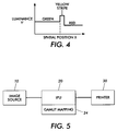
- a saturated red/green edge that has been processed with JPEG compression and decompression, results in an intermediate yellow color produced at the edge.
- the stripe of yellow color is not readily visible, however, when its luminance matches its green neighbor.
- gamut mapping applied to the red/green edge will tend to decrease the luminance of the green side of the edge, while allowing the yellow, which is within gamut, to print at its same luminance level, thus rendering it much more apparent and objectionable.
- US-A 5,579,031 to Liang describes the use of a printer model in the calibration, where the model is iteratively updated to form a final LUT. While the use of a transform like the LUT described in itself inherently provides color matching between the two devices considered, additional color gamut mapping may be used in the development of the LUT, by performing a preselected mathematical manipulation that maps the input set of color values to lie within the range of values from the printer model. Such mathematical manipulation may be as simple as truncation or as complicated as data compression.
- US-A 5,883,632 to Dillinger describes preservation of relative position by geometric transform on "hue pages”.
- Device-space color specifications for two color presentation devices are interrelated through the intermediary of at least one perceptual color space. This interrelation is performed by either tabulations or real-time software processing, and in such a way that color, and color changes, specified in relation to one device-in a control language of that device-are tracked in both the language and the actual performance of the other device.
- This mapping through perceptual space can be used to produce the effect of matching the two device gamuts to each other, so that the full gamuts of both are in effect merged.
- this new kind of mapping preserves relative positions in color space-and thus the capability of the tracking device to maintain distinctions between colors seen on the source/input device that appear very closely similar.
- discrimination between adjacent colors can be supported essentially throughout the gamut of both devices and in particular even very near the lightness extrema and maximum-saturation point on a hue page.
- US-A 5,903,275 to Guay describes a gamut mapping in which saturated colors (i.e., out of gamut colors) are mapped to device saturated values (device printable saturated colors). Colors inside the gamut are mapped to "closest" and other colors to a blend between closest values colorimetrically and saturation.
- the printable colors are measured is some device independent color space, such as L*a*b*.
- the range of colors from some reference color CRT consisting of the colors from black to monitor saturates, and the colors between, then from saturates to white, and the colors between, are calculated. The saturates are assigned colors based on what printable color a user would like to get when the user asks for a saturated CRT color.
- a table is generated that subsamples all colors available to the specified color space. This table fills in entries within the color gamut of the target printer with the closest printable color. Colors out of the printer's gamut are represented by an averaging of the printable colors and of the outer range of colors assigned for the saturates. A requested color is converted to the reference color space, then looked up in the table, and the resulting color specification is sent to the printer.
- US-A 5,450,216 to Kasson describes gamut-mapping color images in device-independent form to device-dependent gamut in a perceptual color space.
- Digital images are mapped to any device-dependent gamut in a manner that minimizes the human visual response both to the luminance and the chrominance changes necessary to force out-of-gamut pixels into the specified device-dependent gamut.
- a "neighborhood gamut mapping" technique considers the subjective visual effects of nearby pixels on the mapping of each pixel. At low spatial frequencies, image luminance is biased toward the luminance in the device-dependent gamut at which the greatest chroma magnitude is available for a fixed hue angle. Spatial filtering exploits the differing spatial frequency regions of insensitive human visual response to both luminance and chrominance changes.
- a method of remapping out-of-gamut colors in an original document, preparatory to use in a system having a different system gamut including: receiving a set of pixels defining at least a portion of an image, each pixel mapped to an original pixel color; for any pixel in said set of pixels, remapping said pixel from said original color to a color which is within said system gamut; comparing colors in said set of pixels before remapping with colors of said set of pixels after remapping and creating a comparison metric therefrom; and applying said comparison metric to said colors after remapping to provide corrective feedback to said pixel set for final color selection within said system gamut.
- the comparison metric is filtered with a spatial filter prior to said applying step.
- the spatial filter is selected to strengthen the comparison metric in high frequency image regions to increase its impact on the gamut remapped colors, and weaken the comparison metric in low frequency areas, to weaken its impact on the gamut remapped colors.
- the comparison metric is a difference between luminance values of said set of pixels mapped to said first set of original colors and said set of pixels mapped to said new set of colors.
- a further embodiment includes filtering said comparison metric prior to corrective feedback.
- said filtering is provided by a linear filter.
- said linear filter strengthens said comparison metric in high spatial frequency regions, to increase the effect thereof on said new set of colors, and weakens said comparison metric in low spatial frequency regions, to weaken the effect thereof on new set of colors.
- said filtering is provided by a non-linear filter.
- a further embodiment includes an additional remapping of said pixels to said new set of colors, to correct any mappings where said corrective feedback has moved said new color out of said system gamut.
- a system for mapping a gamut according to claim 10 is provided.
- mapping from an input color to an output color is not a unique mapping as done in standard gamut mapping techniques. Rather the mapping of an individual color depends on its local neighborhood. This means that a specific color will be mapped to different output colors as a function of neighboring colors.
- the present invention seeks to preserve spatially local luminance variations in the original image, by calculating the difference between the original image luminance and the gamut mapped luminance resulting from using a pixel-bases gamut mapping process. A spatial filter is then applied to the difference signal, and the signal is added back to the gamut-mapped signal. The result is a reduction of the artifacts that arise from standard gamut mapping algorithms.
- a source of original images 10 perhaps a color scanner, a personal computer or workstation with appropriate document or image creation software, a camera or data storage device, produces an image, typically in a device independent manner provides suitable electronic images.
- the images are defined in pixels, each associated with a color defined in terms of CIE color space L*,a*,b*, or some other luminance-chrominance space (L, C1,C2) or an analytic transform thereof.
- An image from image data source 10 is directed to an image processing unit (IPU) 20, which, for the purposes of description includes all of the digital processing requirements to convert an image from its original data representation to a format suitable for printing at printer 30.
- IPU 20 image processing unit
- IPU 20 can take various forms and operational details, and ranges from dedicated, and hardwired or software driven operation in conjunction with high speed printing devices, to printer drivers running on personal computers or workstations driving personal printers. Called out particularly is the gamut mapping function 24, which will be further described below. It will no doubt be appreciated that the colors may be derived in rgb color space, and readily converted to other device independent color spaces where calculations can more readily be performed. This may readily be part of the functionality of IPU 20.
- Printer 30 can be any color printer, printing a plurality of separations which, when superimposed, form a multicolor image.
- the printer functionality could be replaced or arranged in parallel with a display or monitor.
- Gamut mapping function 24 serves to map pixels defined by colors not printable by the printer, or resulting from initial image processing, into colors printable by the real printer. In doing so, out-of-gamut, unprintable colors are mapped to printable colors in accordance with some scheme that attempts to optimize retention of the color relationships within the document. Colors that fall within the output gamut may also be adjusted to retain the relationships to the mapped colors.
- color space definitions that are transforms of CIE XYZ space (1931).
- device dependent space we refer to a color space that is defined only in terms of operation of the device using it. While many color spaces have three dimensions, it is possible to have color spaces with less than three dimensions or more than three dimensions and likewise, it is possible for printers to use less than three colorants or more than four colorants.
- luminance is used generically to encompass the strict definitions of luminance (i.e., the Y component in XYZ) and lightness (i.e. the L* component in L*a*b*).
- Chrominance components C1 and C2 are likewise generic manifestations of opponent color signals, or the equivalent polar representations, chroma and hue. It should understood that exact input luminance values cannot always be preserved through the gamut mapping, since this can result in undesirable trade-offs in the other attributes, hue and chroma. The optimum trade-offs in these attributes for various combinations of device gamuts, image types, and rendering intents is not the focus of the invention, and not discussed in detail here.
- a gamut mapping function G1 is a reasonable pixelwise strategy for large color patches or smooth regions of an image.
- the invention preserves the characteristics of G1 at low spatial frequencies, while preserving high frequency luminance variations in the original image that G1 may have lost or altered.
- the second gamut mapping G2 is designed to approximately preserve these luminance variations.
- gamut mapping function 100 which applies function G1 thereto.
- function G1 can be any gamut mapping function, perhaps represented by either an optimized non-linear function, or a simplistic mapping function, where out of gamut pixels are moved to the nearest "in gamut" plane. There are many such functions, and the precise function chosen is not relevant to the invention.
- the output from the function could be characterized as Y', C1', C2'. From this output, the luminance signal Y' is compared to Y, perhaps in a simple differencing function, 102, producing ⁇ Y.
- a spatial filter 104 operating on an n x m block of values ⁇ Y is used so that the feedback to the gamut mapping function is based on a local area, rather than derived on a pixel by pixel basis.
- the output of spatial filter 104, ⁇ Y' is then used to vary Y' to obtain Y''.
- ⁇ Y' is added to Y' at adder 106.
- the colors defined by Y'', C1', C2' are then subjected to a second gamut mapping function 110, implementing gamut mapping function G2, which may or may not be the same function as G1.
- G1 and G2 may be provided as described in R. S. Gentile, E. Walowit, and J. P. Allebach, A Comparison of Techniques for Color Gamut Mismatch Compensation , SPSE/SPIE Symposium on Electronic Imaging, Los Angeles, pp. 176-181; and E.G. Pariser, An Investigation of Color Gamut Reduction Techniques , IS&T 2nd Symposium on Electronic Publishing, pp. 105-107, 1991.
- gamut mapping functions G1 and G2 are possible and useful in the present application.
- the design of gamut mapping functions G1 and G2, and the spatial filter 104 can depend on many factors, including global and local image characteristics, device characteristics, rendering intent and preference.
- gamut mapping function G1 was chosen to map out-of-gamut colors to the nearest surface point of the same hue
- G2 was chosen to map out-of-gamut colors to a surface point defined by the four steps: I) determine a hue of given out-of-gamut color; ii) calculate cusp point defined as the in-gamut color of maximum chroma at the given hue; iii) determine focal point by projecting the cusp point onto neutral axis while preserving luminance; and iii) mapping the out-of-gamut color to surface in a direction towards the focal point.
- in-gamut colors were unaltered.
- gamut mapping methods include:
- the hue angle thereof is obtained, and then the input color is mapped to the nearest point on the gamut surface within a range of hues about the input hue angle, where the range is greater than 0 and less than 90 degrees.
- a given point P, with hue angle H, is mapped to the closest point on the gamut surface within the region bounded by the lines W-H1 and W-H2.
- a reduced gamut is defined by reducing the chroma of each surface point by a predetermined scale factor.
- a gamut-mapping vector is defined as the shortest distance to the reduced gamut. Map the input color to the original gamut surface in the direction given by this vector.
- Point C is defined as the point of maximum chroma in the hue plane of the input color.
- the process applies pixelwise gamut mapping G1 to the input colors, and computes a difference image ⁇ Y between the luminances of the input and gamut mapped signals. It then adds a filtered version ⁇ Y' of this difference back to the gamut mapped signal Y'.
- This operation might move pixels back out of the gamut, and hence, a second gamut mapping operation G2 is needed to ensure that all colors are within gamut.
- G1 and G2 need not be the same algorithm.
- one possible filter that finds use with respect to the invention is an adaptive linear filter.
- pictorial images require a large filter footprint in order to have a visual effect.
- “large” refers to roughly 15 to 30 pixels (1-dimensional) for a 300 dpi (dot per inch) printer. Smaller filters are not as effective.
- F it may be desirable to choose F as a nonlinear filter.
- the simple linear filter was chosen for ease of demonstration. It should also be noted that the filter can optionally have a gain larger than 1 to enhance detail.
- the filter can be adapted to improve its use by changing the filter footprint as a function of the local image data. In this way, the filter function adapts to local image content. It should be noted that one could also change the filter values or coefficients (rather than the footprint). However, variation of the filter footprint is a preferred option, because a fast implementation exists for a simple, constant-weight blur filter.
- the described filtering function may be implemented by generating an activity metric at activity metric function 400, which applies its output to filter selector 302, to select an appropriate filter for spatial filter 104.
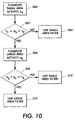
- FIG. 7 shows a flowchart of the adaptive filtering method.
- a small area activity metric a s is computed, conveniently using the absolute value of the small area filter calculation.
- the small area filter is used (step 304). If a s falls within the range, a large area activity a L is computed at step 306, again conveniently using the absolute value of the large area filter calculation.
- values of the activity metrics are compared. If the ratio of the two activity metrics a s /a L is larger than a specified threshold T 3 , a small filter is used at step 310; otherwise a large filter is used at step 312. It should be noted that re-normalization constants in the activity metrics based on the filter size have been omitted.
- the required filters vary with the object or image type of the input, but simple activity measures as described above are sufficient to select the appropriate filters, It should be clear that the selection between two discrete filters was chosen for simplicity and speed and that in the general case the activity measure can be used to derive a filter or to smoothly blend between a number of pre-selected filters.
Landscapes
- Engineering & Computer Science (AREA)
- Multimedia (AREA)
- Signal Processing (AREA)
- Image Processing (AREA)
- Facsimile Image Signal Circuits (AREA)
- Color Image Communication Systems (AREA)
Abstract
Description
Claims (10)
- A method of remapping colors in an original document, preparatory to use in a system having a different system gamut comprising the steps of:receiving a set of pixels defining at least a portion of an image, each pixel associated with an original pixel color;for any pixel in said set of pixels, remapping said pixel from said original pixel color to a new pixel color within said system gamut;comparing original pixel colors in said set of pixels with new pixel colors in said set of pixels and creating a comparison metric therefrom;processing said comparison metric through a spatial filtering operation;combining an output of said spatial filtering operation with said new pixel colors.
- A method as described in claim 1, wherein said remapping is accomplished by remapping each pixel from said original pixel color to said new pixel color, said new pixel color emphasizing preservation of chroma or saturation over preservation of lightness of the pixel.
- A method as described in claim 1, wherein said comparison metric is a difference between an original pixel color luminance component, and a new pixel color luminance.
- A method as described in claim 3 where said combining adds an output of said spatial filtering to said new pixel color luminance component.
- A method as described in claim 1 where said spatial filtering uses a linear filter.
- A method as described in claim 1 wherein said spatial filtering strengthens said comparison metric in high spatial frequency regions to increase the effect thereof on new pixel colors, and weakens said comparison metric in low spatial frequency regions to weaken the effect thereof on new pixel colors.
- A method as described in claim 1, further comprising an additional remapping of said set of pixels associated with new pixel colors to adjusted new pixel colors, where said combining has moved said new pixel colors out of said system gamut.
- A method as described in claim 7, wherein said additional remapping comprises:determining a hue of each said new pixel color;calculating a cusp point, defined as a point on a printer gamut surface corresponding to a maximum achievable chroma for said hue;determining a focal point, defined as a projection of said cusp point into a neutral axis of a color space, in a manner that preserves luminance; andmapping pixel colors that are out of said system gamut to said adjusted new color on a surface of said system gamut in a direction in said color space towards said focal point.
- A method of remapping colors in an original document, preparatory to use in a system having a different system gamut than originally applied, including:receiving a set of pixels defining at least a portion of an image, each pixel therein mapped to a first set of original colorsfor each pixel in said set, remapping said pixel from said set of original colors to a new set of colors within said system gamut;determining a comparison metric, comparing said set of pixels mapped to said first set of original colors and said set of pixels mapped to said new set of colors;applying said comparison metric to said colors after remapping to provide corrective spatial feedback to said pixel set to adjust color selection within said system gamut.
- A gamut mapping system includingan image input, receiving pixels directed thereto mapped to a first set of colors, which may not be reproducible at a selected output device;a first gamut mapping device, remapping said pixels mapped to said first set of colors to a second set of colors reproducible at said selected output device;a corrective spatial feedback system, having:a first input receiving said pixels mapped to said first set of colors,a second input receiving said pixels mapped to said second set of colors, and producing a comparison signal representing a difference therebetween;a signal adder, adding said comparison signal to a luminance value of said pixels mapped to said second set of colors, to adjust said luminance values, while maintaining other color defining values.
Applications Claiming Priority (2)
| Application Number | Priority Date | Filing Date | Title |
|---|---|---|---|
| US435308 | 1989-11-13 | ||
| US09/435,308 US6646762B1 (en) | 1999-11-05 | 1999-11-05 | Gamut mapping preserving local luminance differences |
Publications (3)
| Publication Number | Publication Date |
|---|---|
| EP1098510A2 true EP1098510A2 (en) | 2001-05-09 |
| EP1098510A3 EP1098510A3 (en) | 2003-12-17 |
| EP1098510B1 EP1098510B1 (en) | 2007-02-21 |
Family
ID=23727868
Family Applications (1)
| Application Number | Title | Priority Date | Filing Date |
|---|---|---|---|
| EP00123933A Expired - Lifetime EP1098510B1 (en) | 1999-11-05 | 2000-11-03 | Gamut mapping preserving local luminance differences |
Country Status (4)
| Country | Link |
|---|---|
| US (1) | US6646762B1 (en) |
| EP (1) | EP1098510B1 (en) |
| JP (1) | JP2001169136A (en) |
| DE (1) | DE60033484T2 (en) |
Cited By (5)
| Publication number | Priority date | Publication date | Assignee | Title |
|---|---|---|---|---|
| WO2003079669A1 (en) * | 2002-03-13 | 2003-09-25 | Hewlett-Packard Company | Variational models for spatially dependent gamut mapping |
| WO2003079670A1 (en) * | 2002-03-13 | 2003-09-25 | Hewlett-Packard Company | Reducing halos in spatially dependent gamut mapping |
| WO2006029760A3 (en) * | 2004-09-15 | 2006-06-15 | Oce Printing Systems Gmbh | Method and device for converting source image data into target image data |
| WO2012072415A1 (en) * | 2010-11-30 | 2012-06-07 | Oce-Technologies B.V. | Method of rendering a colour image with spatial gamut mapping |
| EP1968306B1 (en) * | 2007-02-28 | 2019-08-07 | Xerox Corporation | Hard copy out of gamut detection |
Families Citing this family (26)
| Publication number | Priority date | Publication date | Assignee | Title |
|---|---|---|---|---|
| US7072072B1 (en) * | 2000-05-02 | 2006-07-04 | Xerox Corporation | Color rendering optimized for text and line art |
| US7161710B1 (en) | 2000-09-01 | 2007-01-09 | Adobe Systems Incorporated | Composite rendering intent for color proofing applications |
| US7227666B1 (en) * | 2000-09-01 | 2007-06-05 | Adobe Systems Incorporated | Dynamic selection of rendering intent for color proofing transforms |
| GB0022071D0 (en) * | 2000-09-08 | 2000-10-25 | Pandora Int Ltd | Image processing |
| US20020172431A1 (en) * | 2001-03-07 | 2002-11-21 | Atkins C. Brian | Digital image appearance enhancement and compressibility improvement method and system |
| US7355745B2 (en) * | 2001-04-13 | 2008-04-08 | Hewlett Packard | Document-to-printer color gamut matching |
| US6882449B2 (en) * | 2001-06-18 | 2005-04-19 | Hewlett-Packard Development Company, L.P. | Space varying gamut mapping |
| US6961477B2 (en) * | 2001-07-12 | 2005-11-01 | Canon Kabushiki Kaisha | Image-based selection of gamut mapping |
| US7652808B2 (en) * | 2003-12-11 | 2010-01-26 | Xerox Corporation | Spatially varying luminance compression gamut mapping system and method |
| US7382915B2 (en) * | 2004-03-16 | 2008-06-03 | Xerox Corporation | Color to grayscale conversion method and apparatus |
| US8432582B2 (en) * | 2004-08-20 | 2013-04-30 | Xerox Corporation | Uniformity compensation in halftoned images |
| US7426312B2 (en) * | 2005-07-05 | 2008-09-16 | Xerox Corporation | Contrast enhancement of images |
| KR100664958B1 (en) * | 2005-07-11 | 2007-01-04 | 삼성전자주식회사 | Printer and method for outputting optimally converted image using predefined data and color characteristic information |
| US7822270B2 (en) * | 2005-08-31 | 2010-10-26 | Microsoft Corporation | Multimedia color management system |
| US7573620B2 (en) * | 2005-09-01 | 2009-08-11 | Microsoft Corporation | Gamuts and gamut mapping |
| US8274714B2 (en) * | 2005-11-30 | 2012-09-25 | Microsoft Corporation | Quantifiable color calibration |
| KR101225059B1 (en) * | 2006-02-24 | 2013-01-23 | 삼성전자주식회사 | Apparatus and method for enhancing color device-adaptively |
| KR20070091853A (en) * | 2006-03-07 | 2007-09-12 | 삼성전자주식회사 | Image Adaptive Color Reproduction Apparatus and Method |
| JP2007274584A (en) * | 2006-03-31 | 2007-10-18 | Canon Inc | Color processing method and apparatus |
| US7768671B2 (en) * | 2006-09-18 | 2010-08-03 | Xerox Corporation | Color image gamut enhancement preserving spatial variation |
| US8050496B2 (en) * | 2007-01-09 | 2011-11-01 | Sharp Laboratories Of America, Inc. | Color gamut mapping/enhancement technique using skin color detection |
| US20080192269A1 (en) * | 2007-02-12 | 2008-08-14 | Sharp Laboratories Of America, Inc. | Gamut mapping for printer color rendering |
| US8103096B2 (en) * | 2008-08-29 | 2012-01-24 | Xerox Corporation | System and method for color space conversion with reduced artifacts |
| US8265387B2 (en) * | 2009-04-24 | 2012-09-11 | Xerox Corporation | Adaptive spatial gamut mapping via dynamic thresholding |
| US8665290B2 (en) * | 2009-05-28 | 2014-03-04 | Canon Kabushiki Kaisha | Image-based source gamut adjustment for compression-type gamut mapping algorithm |
| JP7105737B2 (en) * | 2018-06-29 | 2022-07-25 | キヤノン株式会社 | Image processing device, image processing method, and program |
Family Cites Families (9)
| Publication number | Priority date | Publication date | Assignee | Title |
|---|---|---|---|---|
| US5012333A (en) * | 1989-01-05 | 1991-04-30 | Eastman Kodak Company | Interactive dynamic range adjustment system for printing digital images |
| US5883632A (en) | 1992-05-04 | 1999-03-16 | Hewlett-Packard Company | Coordinating color produced by two devices--using a hue-controlled machine color space, or surface scaling |
| EP0604755B1 (en) | 1992-12-15 | 1999-05-12 | E.I. Du Pont De Nemours And Company | Color matching method and apparatus |
| US5608824A (en) * | 1993-01-22 | 1997-03-04 | Olympus Optical Co., Ltd. | Image processing apparatus in which filters having different filtering characteristics can be switched among themselves |
| EP0745304A1 (en) | 1994-02-16 | 1996-12-04 | Apple Computer, Inc. | Subjectively pleasing color gamut mapping in a color computer graphics system |
| US5450216A (en) | 1994-08-12 | 1995-09-12 | International Business Machines Corporation | Color image gamut-mapping system with chroma enhancement at human-insensitive spatial frequencies |
| US5611030A (en) * | 1994-09-16 | 1997-03-11 | Apple Computer, Inc. | Subjectively pleasing color gamut mapping in a color computer graphics system |
| JP3639405B2 (en) * | 1997-03-07 | 2005-04-20 | 東洋インキ製造株式会社 | Color gamut compression method and apparatus |
| US6181445B1 (en) * | 1998-03-30 | 2001-01-30 | Seiko Epson Corporation | Device-independent and medium-independent color matching between an input device and an output device |
-
1999
- 1999-11-05 US US09/435,308 patent/US6646762B1/en not_active Expired - Fee Related
-
2000
- 2000-10-24 JP JP2000323411A patent/JP2001169136A/en active Pending
- 2000-11-03 EP EP00123933A patent/EP1098510B1/en not_active Expired - Lifetime
- 2000-11-03 DE DE60033484T patent/DE60033484T2/en not_active Expired - Lifetime
Cited By (8)
| Publication number | Priority date | Publication date | Assignee | Title |
|---|---|---|---|---|
| WO2003079669A1 (en) * | 2002-03-13 | 2003-09-25 | Hewlett-Packard Company | Variational models for spatially dependent gamut mapping |
| WO2003079670A1 (en) * | 2002-03-13 | 2003-09-25 | Hewlett-Packard Company | Reducing halos in spatially dependent gamut mapping |
| US6826304B2 (en) | 2002-03-13 | 2004-11-30 | Hewlett-Packard Development Company, L.P. | Reducing halos in spatially dependent gamut mapping |
| US6873439B2 (en) | 2002-03-13 | 2005-03-29 | Hewlett-Packard Development Company, L.P. | Variational models for spatially dependent gamut mapping |
| WO2006029760A3 (en) * | 2004-09-15 | 2006-06-15 | Oce Printing Systems Gmbh | Method and device for converting source image data into target image data |
| CN101019412B (en) * | 2004-09-15 | 2010-07-07 | Oce印刷系统有限公司 | Method and device for converting source image data into target image data |
| EP1968306B1 (en) * | 2007-02-28 | 2019-08-07 | Xerox Corporation | Hard copy out of gamut detection |
| WO2012072415A1 (en) * | 2010-11-30 | 2012-06-07 | Oce-Technologies B.V. | Method of rendering a colour image with spatial gamut mapping |
Also Published As
| Publication number | Publication date |
|---|---|
| EP1098510A3 (en) | 2003-12-17 |
| EP1098510B1 (en) | 2007-02-21 |
| JP2001169136A (en) | 2001-06-22 |
| US6646762B1 (en) | 2003-11-11 |
| DE60033484T2 (en) | 2007-05-31 |
| DE60033484D1 (en) | 2007-04-05 |
Similar Documents
| Publication | Publication Date | Title |
|---|---|---|
| US6646762B1 (en) | Gamut mapping preserving local luminance differences | |
| EP1098511B1 (en) | Gamut mapping preserving local luminance differences with adaptive spatial filtering | |
| US6414690B1 (en) | Gamut mapping using local area information | |
| US7382915B2 (en) | Color to grayscale conversion method and apparatus | |
| US6388674B1 (en) | Gamut mapping method and apparatus | |
| US7072084B2 (en) | Color converting device emphasizing a contrast of output color data corresponding to a black character | |
| EP0971314B1 (en) | A method for preserving image detail when adjusting the contrast of a digital image | |
| US6342951B1 (en) | Gamut mapping algorithm using inverted gamma function | |
| EP0611230B1 (en) | Method and associated apparatus for transforming input color values in an input color space to output color values in an output color space | |
| US5982924A (en) | Method and system for reproducing color images as duotones | |
| EP1111907B1 (en) | A method for enhancing a digital image with noise-dependent control of texture | |
| US7545976B2 (en) | Method and apparatus for associating image enhancement with color | |
| Bala et al. | Gamut mapping to preserve spatial luminance variations | |
| US20050105147A1 (en) | Automatic saturation adjustment | |
| JPH0879545A (en) | Image mapping method,image display system and image printingsystem | |
| EP1111906A2 (en) | A method for enhancing the edge contrast of a digital image independently from the texture | |
| JP4536431B2 (en) | Method and system for controlling a color output device | |
| JP2001128022A (en) | Image processing apparatus, method, recording medium, and computer program | |
| EP1152373A2 (en) | Robust colorimetry transform | |
| US7379208B2 (en) | Hybrid gamut mapping | |
| Balasubramanian et al. | Gamut mapping to preserve spatial luminance variations | |
| JP2600573B2 (en) | Color image saturation enhancement method and apparatus | |
| WO2009093294A1 (en) | Image signal processing device and image signal processing program | |
| Samadzadegan et al. | Spatially resolved joint spectral gamut mapping and separation | |
| JP2006033196A (en) | Color correction apparatus, image forming apparatus, color correction method, color correction program, and computer-readable recording medium |
Legal Events
| Date | Code | Title | Description |
|---|---|---|---|
| PUAI | Public reference made under article 153(3) epc to a published international application that has entered the european phase |
Free format text: ORIGINAL CODE: 0009012 |
|
| AK | Designated contracting states |
Kind code of ref document: A2 Designated state(s): AT BE CH CY DE DK ES FI FR GB GR IE IT LI LU MC NL PT SE TR |
|
| AX | Request for extension of the european patent |
Free format text: AL;LT;LV;MK;RO;SI |
|
| PUAL | Search report despatched |
Free format text: ORIGINAL CODE: 0009013 |
|
| AK | Designated contracting states |
Kind code of ref document: A3 Designated state(s): AT BE CH CY DE DK ES FI FR GB GR IE IT LI LU MC NL PT SE TR |
|
| AX | Request for extension of the european patent |
Extension state: AL LT LV MK RO SI |
|
| 17P | Request for examination filed |
Effective date: 20040617 |
|
| AKX | Designation fees paid |
Designated state(s): DE FR GB |
|
| GRAP | Despatch of communication of intention to grant a patent |
Free format text: ORIGINAL CODE: EPIDOSNIGR1 |
|
| GRAS | Grant fee paid |
Free format text: ORIGINAL CODE: EPIDOSNIGR3 |
|
| GRAA | (expected) grant |
Free format text: ORIGINAL CODE: 0009210 |
|
| AK | Designated contracting states |
Kind code of ref document: B1 Designated state(s): DE FR GB |
|
| REG | Reference to a national code |
Ref country code: GB Ref legal event code: FG4D |
|
| REF | Corresponds to: |
Ref document number: 60033484 Country of ref document: DE Date of ref document: 20070405 Kind code of ref document: P |
|
| ET | Fr: translation filed | ||
| PLBE | No opposition filed within time limit |
Free format text: ORIGINAL CODE: 0009261 |
|
| STAA | Information on the status of an ep patent application or granted ep patent |
Free format text: STATUS: NO OPPOSITION FILED WITHIN TIME LIMIT |
|
| 26N | No opposition filed |
Effective date: 20071122 |
|
| PGFP | Annual fee paid to national office [announced via postgrant information from national office to epo] |
Ref country code: DE Payment date: 20131022 Year of fee payment: 14 Ref country code: FR Payment date: 20131121 Year of fee payment: 14 Ref country code: GB Payment date: 20131025 Year of fee payment: 14 |
|
| REG | Reference to a national code |
Ref country code: DE Ref legal event code: R119 Ref document number: 60033484 Country of ref document: DE |
|
| GBPC | Gb: european patent ceased through non-payment of renewal fee |
Effective date: 20141103 |
|
| REG | Reference to a national code |
Ref country code: FR Ref legal event code: ST Effective date: 20150731 |
|
| PG25 | Lapsed in a contracting state [announced via postgrant information from national office to epo] |
Ref country code: GB Free format text: LAPSE BECAUSE OF NON-PAYMENT OF DUE FEES Effective date: 20141103 Ref country code: DE Free format text: LAPSE BECAUSE OF NON-PAYMENT OF DUE FEES Effective date: 20150602 |
|
| PG25 | Lapsed in a contracting state [announced via postgrant information from national office to epo] |
Ref country code: FR Free format text: LAPSE BECAUSE OF NON-PAYMENT OF DUE FEES Effective date: 20141201 |