EP1098450A2 - Path timing detection circuit and detection method thereof - Google Patents
Path timing detection circuit and detection method thereof Download PDFInfo
- Publication number
- EP1098450A2 EP1098450A2 EP00123869A EP00123869A EP1098450A2 EP 1098450 A2 EP1098450 A2 EP 1098450A2 EP 00123869 A EP00123869 A EP 00123869A EP 00123869 A EP00123869 A EP 00123869A EP 1098450 A2 EP1098450 A2 EP 1098450A2
- Authority
- EP
- European Patent Office
- Prior art keywords
- arithmetic operation
- circuit
- correlative arithmetic
- path
- correlative
- Prior art date
- Legal status (The legal status is an assumption and is not a legal conclusion. Google has not performed a legal analysis and makes no representation as to the accuracy of the status listed.)
- Withdrawn
Links
- 238000001514 detection method Methods 0.000 title claims description 43
- 230000001955 cumulated effect Effects 0.000 claims abstract description 28
- 238000000034 method Methods 0.000 claims abstract description 20
- 238000012544 monitoring process Methods 0.000 claims abstract description 19
- 230000002596 correlated effect Effects 0.000 description 14
- 238000005070 sampling Methods 0.000 description 8
- 230000005540 biological transmission Effects 0.000 description 7
- 230000000875 corresponding effect Effects 0.000 description 7
- 238000010276 construction Methods 0.000 description 6
- 238000012935 Averaging Methods 0.000 description 4
- 230000000694 effects Effects 0.000 description 4
- 230000001174 ascending effect Effects 0.000 description 3
- 230000004888 barrier function Effects 0.000 description 3
- 230000003111 delayed effect Effects 0.000 description 3
- 238000007792 addition Methods 0.000 description 2
- 230000015556 catabolic process Effects 0.000 description 2
- 238000006243 chemical reaction Methods 0.000 description 2
- 238000006731 degradation reaction Methods 0.000 description 2
- 238000010586 diagram Methods 0.000 description 2
- 238000005259 measurement Methods 0.000 description 2
- 238000004891 communication Methods 0.000 description 1
- 238000005562 fading Methods 0.000 description 1
- 239000000835 fiber Substances 0.000 description 1
- 230000002452 interceptive effect Effects 0.000 description 1
- 238000010295 mobile communication Methods 0.000 description 1
- 230000010363 phase shift Effects 0.000 description 1
- 238000004513 sizing Methods 0.000 description 1
Images





Classifications
-
- H—ELECTRICITY
- H04—ELECTRIC COMMUNICATION TECHNIQUE
- H04B—TRANSMISSION
- H04B1/00—Details of transmission systems, not covered by a single one of groups H04B3/00 - H04B13/00; Details of transmission systems not characterised by the medium used for transmission
- H04B1/69—Spread spectrum techniques
- H04B1/707—Spread spectrum techniques using direct sequence modulation
- H04B1/7073—Synchronisation aspects
- H04B1/7075—Synchronisation aspects with code phase acquisition
-
- H—ELECTRICITY
- H04—ELECTRIC COMMUNICATION TECHNIQUE
- H04B—TRANSMISSION
- H04B1/00—Details of transmission systems, not covered by a single one of groups H04B3/00 - H04B13/00; Details of transmission systems not characterised by the medium used for transmission
- H04B1/69—Spread spectrum techniques
- H04B1/707—Spread spectrum techniques using direct sequence modulation
- H04B1/7097—Interference-related aspects
- H04B1/711—Interference-related aspects the interference being multi-path interference
- H04B1/7115—Constructive combining of multi-path signals, i.e. RAKE receivers
- H04B1/7117—Selection, re-selection, allocation or re-allocation of paths to fingers, e.g. timing offset control of allocated fingers
Definitions
- the present invention relates generally to a path timing detection circuit and a detection method thereof. More particularly, the invention relates to a path timing detection circuit and a detection method thereof to be used for Code Division Multiple Access (CDMA) receiver device.
- CDMA Code Division Multiple Access
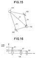
- Fig. 16 is an explanatory illustration of a reception timing for explaining the multiple paths.
- an ordinate axis represents a signal level and an abscissa axis represents a time.
- the signal S2 having the shortest transmission path next to the signal S1 is received at second, and the signal S3 having the longest transmission path is received at the last.
- a result of correlation resulting from correlating arithmetic operation over a predetermined correlation length (number of times of cumulation) L is output.
- the correlation length can be relatively short when level of noise and interfering wave in the propagation environment is low.
- An object of the present invention to provide a multiple path timing detecting circuit and a detection method thereof, which can save consumed current by omitting correlative arithmetic operation (cumulation) in unnecessarily long correlation length L when a propagation environment is relatively good, and a plurality of paths can be detected with high precision.
- a path timing detector circuit performing a correlative arithmetic operation of a spread modulation wave and a predetermined spread code with a given period of delay and detecting a reception timing of the spread modulation signal via each path on the basis of a result of the correlative arithmetic operation, comprises:
- the correlative arithmetic operation may be performed for a plurality of times with the given period of delay.
- the path timing detector circuit may further comprise holding means for holding a number of times of cumulation at the time of stopping of the correlative arithmetic operation, and path candidates classifying means for classifying detected candidates according to held number of times of cumulation.
- the path timing detector circuit may comprise a plurality of correlative arithmetic operation means for performing plurality of correlative arithmetic operation simultaneously corresponding to a plurality of delay period. Also, the path timing detector circuit may further comprise second correlative arithmetic operation control means for stopping arithmetic operation in all of the correlative arithmetic operation when number of cumulated values exceeding the threshold value, exceeds a predetermined number.
- a plurality of correlative arithmetic operation means may be grouped to form sets per at least two, and the path timing detector circuit further includes OR means for obtaining OR of the outputs of one set of monitoring means with respect to one set of correlative arithmetic operation means, the correlative arithmetic operation control means stops correlative arithmetic operation by one set of correlative arithmetic operation means on the basis of the output from the OR means.
- the cumulation circuit may include an adder which overflows when the threshold value is exceeded, and the monitoring means makes judgment that the threshold value is exceeded upon occurrence of overflow.
- the path timing detector circuit may further include average value deriving means for deriving an average value of number of times of cumulation of path candidate output from the path candidate classifying means. Furthermore, the path timing detector circuit may further comprise threshold value estimating means for estimating the threshold value from the output from a plurality of correlative arithmetic operation means.
- the path timing detector circuit may further comprise a reception field intensity estimating means for estimating a field intensity of a reception wave on the basis of number of times of cumulation at a time where the cumulated value in the process of the correlative arithmetic operation exceeds the threshold value and an AGC coefficient of a high request reception circuit upon reception of the reception wave causing the cumulated value.
- a path timing detection method performing a correlative arithmetic operation of a spread modulation wave and a predetermined spread code with a given period of delay and detecting a reception timing of the spread modulation signal via each path on the basis of a result of the correlative arithmetic operation, comprises:
- the correlative arithmetic operation may be performed for a plurality of times with the given period of delay.
- the path timing detector method may further comprise a third step of classifying detected candidates according to held number of times of cumulation upon stopping of the correlative arithmetic operation at the second step.
- Fig. 1 is a constructional illustration showing the best mode of a path timing detection circuit according to the present invention
- Fig. 2 is a constructional illustration of a major part of a CDMA receiver device including a path timing detection circuit according to the present invention.
- the CDMA receiving device is constructed with an antenna portion 1, a high frequency receiver circuit portion 2, an A/D converter portion 3, a RAKE finger portion 4, a RAKE combining portion 5 and a path timing detecting portion 6.
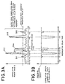
- Figs. 3A and 3B are characteristic charts of one example of the delay profile of the propagation path.
- Figs. 3A and 3B show another example of Fig. 16.
- an ordinate axis represents a correlated power value (correlated value) E and an abscissa axis represents a propagation delay period t (namely, elapsed time).
- Fig. 3A an ordinate axis represents a correlated power value (correlated value) E and an abscissa axis represents a propagation delay period t (namely, elapsed time).
- the path timing detection circuit 6 is provided with a PN generator 11 generating the spread code, a correlator 14 constructed with a multiplier 12 performing correlative arithmetic operation of a generated PN series and the reception signal and a cumulator 13, a delay circuit 15 for calculating correlation values at respective reception timing, a correlation length measuring portion 16 for measuring a correlation length L by counting number of times of cumulation in the cumulator 13, a power comparator 17 comparing the result of correlative arithmetic operation and a threshold value 21, a correlation length storing portion 18 for storing the correlation length L when the correlation value exceeds the threshold value 21, and a path order sorting portion 19 sorting the cumulation number (correlation length) L in ascending order from the minimum value until the threshold value 21 is reached at each reception timing.
- the path timing detection circuit 6 performs correlative arithmetic operation of the spread code P and the reception signal R at the reception timing depending upon the delay circuit 15 per delay amount.
- the correlative arithmetic operation may be performed either when the reception data is real data processed by Bi-Phase Shift Keying (BPSK) or when the reception data is a complex data modulated by Quadrature Phase Shift Keying (QPSK).
- BPSK Bi-Phase Shift Keying
- QPSK Quadrature Phase Shift Keying
- the result of correlative arithmetic operation over a given correlation length (number of cumulation) is output to make judgment that the reception wave (path) is detected when the correlation value level is high.
- the correlation length in the correlative arithmetic operation can be relatively short when the level of noise and interference wave in the propagation environment is low, and the path buried in the noise cannot be detected unless the correlation length is set sufficiently long when the propagation environment is bad.
- the present invention without performing correlative arithmetic operation over the given correlation length, judgment is made as effective path at a timing where the threshold value set the correlation value E, by the power comparator 17 to stop correlative arithmetic operation.
- the correlation length L is stored in the correlation length storing portion 18.
- the correlative arithmetic operation is performed at several points with shifting the value of the delay circuit 15 for searching the path position exceeding the threshold value 21.
- the preferential order of the reception timing such as, first path, second path and so forth from the one having the shortest correlation length among those stored in the correlation length storing portion 18 are decided.
- Figs. 3A and 3B there are shown relationship between the correlated power value E and the correlation length L.
- the correlation value E does not reach the threshold value 21 even at the maximum correlation length L, namely even when cumulation is performed at the maximum number of times.
- the correlated power value E reaches the threshold value 21 before number of times of the cumulation does not reach the maximum number of times of correlation.
- the fact that the correlation power value E reaches the threshold value 21 at smaller number of times of cumulation in comparison with others means that the power value of such reception signal is higher than other reception signal.
- PN generator 11 of Fig. 1 and the RAKE fiber portion 4 of Fig. 2 are well known to those skilled in the art and are not directly related to the present invention. Therefore, discussion for these components will be omitted in order to keep the disclosure simple enough to facilitate clear understanding of the present invention.
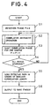
- Fig. 5 is a flowchart showing the operation of the correlator 14.
- a correlation length counter n indicating the length of the correlation length L is cleared to zero to clear the value of the cumulator 13 (S11).
- the path timing detection circuit 6 in the shown embodiment since the correlative arithmetic operation is terminated when the set threshold value 21 is exceeded, the path can be detected at short correlation length when the propagation environment is good so as not to perform extra arithmetic operation. Therefore, current consumption can be reduced. Also, bit number of the result of correlation can be reduced to be smaller than that of the result of normal arithmetic operation. Therefore , bit number of the cumulator 13 and a buffer storing the cumulated value D can be reduced to reduce circuit scale.
- the paths can be assigned to the finger from those having higher preferential order to prevent degradation of performance.
- the path timing detection circuit 6 has one correlator 14, this first embodiment has a plurality of correlators.
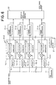
- Fig. 6 is a constructional illustration of the first embodiment of the path timing detection circuit 6.
- components similar to the former embodiment (Fig. 1) will be identified by the same reference numerals and discussion therefor will be omitted in order to avoid redundant discussion and whereby to keep the disclosure simple enough to facilitate clear understanding of the present invention.
- a path timing detecting circuit 6-2 is constructed with one PN generator 11, n in number of delay circuits 15 (15-1 to 15-n), n in number of correlator 14 (14-1 to 14-n), n in number of power comparators 17 (17-1 to 17-n), one threshold value 21 and one effective path number counting portion 22.
- n number of delay circuits 15 mutually different delay times are set with a predetermined constant difference.
- the delay time t 11 is set in the delay circuit 15-1
- the delay time t 12 is set in the delay circuit 15-2
- the delay time t 13 is set in the delay circuit 15-3
- the delay time t 14 is set in the delay circuit 15-4 (not shown)
- the delay time t 15 is set in the delay circuit 15-5 (not shown)
- the delay time t 16 is set in the delay circuit 15-6 (not shown), or otherwise, times slightly before respective delay times are set for respective delay circuits.
- the effective path number counting portion 22 stores the delay time t 12 at which the signal S12 is obtained, and the correlation length L thereof.
- the effective path number counting portion 22 stores the delay time t 12 , t 15 , t 14 and t 16 between the signal S15 having the second shortest correlation length L next to the signal S12, the signal S14 having the correlation length of the length L shorter next to the signal S15 and the signal S16 having the correlation length of the length L shorter next to the signal S14, and their correlation lengths L. Then, the combination of the delay time t and the corresponding correlation length L are fed to each RAKE finger.
- the path timing detection circuit 6-2 terminates arithmetic operation in all of the correlators 14-1 to 14-n.
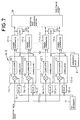
- Fig. 7 is a constructional illustration of the second embodiment of the path timing detector circuit according to the present invention.
- a path timing detection circuit 6-3 in the second embodiment has correlators 14 grouped per two.
- the correlators 14-1 and 14-2 form one group to input outputs of the power comparators 17-1 and 17-2 to an OR circuit 23.
- two power comparators 17 forms a set.
- one set may be formed with three or more power comparators to achieve similar effect.
Landscapes
- Engineering & Computer Science (AREA)
- Computer Networks & Wireless Communication (AREA)
- Signal Processing (AREA)
- Synchronisation In Digital Transmission Systems (AREA)
- Radar Systems Or Details Thereof (AREA)
Abstract
Description
Claims (23)
- A path timing detector circuit performing a correlative arithmetic operation of a spread modulation wave and a predetermined spread code with a given period of delay and detecting a reception timing of said spread modulation signal via each path on the basis of a result of the correlative arithmetic operation, comprising:monitoring means for monitoring whether a cumulated value exceeds a threshold value during a process of the correlative arithmetic operation; andcorrelative arithmetic operation control means responsive to said cumulated value in excess of said threshold value for stopping the correlative arithmetic operation in a corresponding delay period.
- A path timing detector circuit as set forth in claim 1, wherein said correlative arithmetic operation is performed for a plurality of times with said given period of delay.
- A path timing detector circuit as set forth in claim 1, which further comprisesholding means for holding a number of times of cumulation at the time of stopping of said correlative arithmetic operation ; andpath candidates classifying means for classifying detected candidates according to held number of times of cumulation.
- A path timing detector circuit as set forth in claim 1, which comprises a plurality of correlative arithmetic operation means for performing plurality of correlative arithmetic operation simultaneously corresponding to a plurality of delay period.
- A path timing detector circuit as set forth in claim 1, which further comprises second correlative arithmetic operation control means for stopping arithmetic operation in all of said correlative arithmetic operation when number of cumulated values exceeding said threshold value, exceeds a predetermined number.
- A path timing detector circuit as set forth in claim 1, wherein a plurality of correlative arithmetic operation means are grouped to form sets per at least two, and said path timing detector circuit further includes OR means for obtaining OR of the outputs of one set of monitoring means with respect to one set of correlative arithmetic operation means, said correlative arithmetic operation control means stops correlative arithmetic operation by one set of correlative arithmetic operation means on the basis of the output from said OR means.
- A path timing detector circuit as set forth in claim 1, wherein said cumulation circuit includes an adder which overflows when said threshold value is exceeded, and said monitoring means makes judgment that the threshold value is exceeded upon occurrence of overflow.
- A path timing detector circuit as set forth in claim 3, which further includes average value deriving means for deriving an average value of number of times of cumulation of path candidate output from said path candidate classifying means.
- A path timing detector circuit as set forth in claim 4, which further comprises threshold value estimating means for estimating said threshold value from the output from a plurality of correlative arithmetic operation means.
- A path timing detector circuit as set forth in claim 1, which further comprises a reception field intensity estimating means for estimating a field intensity of a reception wave on the basis of number of times of cumulation at a time where the cumulated value in the process of the correlative arithmetic operation exceeds the threshold value and an AGC coefficient of a high frequency reception circuit upon reception of the reception wave causing the cumulated value.
- A path timing detection method performing a correlative arithmetic operation of a spread modulation wave and a predetermined spread code with a given period of delay and detecting a reception timing of said spread modulation signal via each path on the basis of a result of the correlative arithmetic operation, comprising:a first step of monitoring whether a cumulated value exceeds a threshold value during a process of the correlative arithmetic operation; anda second step initiated in responsive to said cumulated value in excess of said threshold value, of stopping the correlative arithmetic operation in a corresponding delay period.
- A path timing detector method as set forth in claim 11, wherein said correlative arithmetic operation is performed for a plurality of times with said given period of delay.
- A path timing detector method as set forth in claim 11, which further comprises a third step of classifying detected candidates according to held number of times of cumulation upon stopping of said correlative arithmetic operation at said second step.
- A path timing detector circuit performing a correlative arithmetic operation of a spread modulation wave and a predetermined spread code with a given period of delay and detecting a reception timing of said spread modulation signal via each path on the basis of a result of the correlative arithmetic operation, comprising:monitoring circuit for monitoring whether a cumulated value exceeds a threshold value during a process of the correlative arithmetic operation; andcorrelative arithmetic operation control circuit responsive to said cumulated value in excess of said threshold value for stopping the correlative arithmetic operation in a corresponding delay period.
- A path timing detector circuit as set forth in claim 14, wherein said correlative arithmetic operation is performed for a plurality of times with said given period of delay.
- A path timing detector circuit as set forth in claim 14, which further comprisesholding circuit for holding a number of times of cumulation at the time of stopping of said correlative arithmetic operation ; andpath candidates classifying circuit for classifying detected candidates according to held number of times of cumulation.
- A path timing detector circuit as set forth in claim 14, which comprises a plurality of correlative arithmetic operation circuit for performing plurality of correlative arithmetic operation simultaneously corresponding to a plurality of delay period.
- A path timing detector circuit as set forth in claim 14, which further comprises second correlative arithmetic operation control circuit for stopping arithmetic operation in all of said correlative arithmetic operation when number of cumulated values exceeding said threshold value, exceeds a predetermined number.
- A path timing detector circuit as set forth in claim 14, wherein a plurality of correlative arithmetic operation circuit are grouped to form sets per at least two, and said path timing detector circuit further includes OR circuit for obtaining OR of the outputs of one set of monitoring circuit with respect to one set of correlative arithmetic operation circuit, said correlative arithmetic operation control circuit stops correlative arithmetic operation by one set of correlative arithmetic operation circuit on the basis of the output from said OR circuit.
- A path timing detector circuit as set forth in claim 14, wherein said cumulation circuit includes an adder which overflows when said threshold value is exceeded, and said monitoring circuit makes judgment that the threshold value is exceeded upon occurrence of overflow.
- A path timing detector circuit as set forth in claim 16, which further includes average value deriving circuit for deriving an average value of number of times of cumulation of path candidate output from said path candidate classifying circuit.
- A path timing detector circuit as set forth in claim 17, which further comprises threshold value estimating circuit for estimating said threshold value from the output from a plurality of correlative arithmetic operation circuit.
- A path timing detector circuit as set forth in claim 14, which further comprises a reception field intensity estimating circuit for estimating a field intensity of a reception wave on the basis of number of times of cumulation at a time where the cumulated value in the process of the correlative arithmetic operation exceeds the threshold value and an AGC coefficient of a high frequency reception circuit upon reception of the reception wave causing the cumulated value.
Applications Claiming Priority (2)
| Application Number | Priority Date | Filing Date | Title |
|---|---|---|---|
| JP31316699A JP3358603B2 (en) | 1999-11-04 | 1999-11-04 | Path timing detection circuit and its detection method |
| JP31316699 | 1999-11-04 |
Publications (2)
| Publication Number | Publication Date |
|---|---|
| EP1098450A2 true EP1098450A2 (en) | 2001-05-09 |
| EP1098450A3 EP1098450A3 (en) | 2004-01-21 |
Family
ID=18037907
Family Applications (1)
| Application Number | Title | Priority Date | Filing Date |
|---|---|---|---|
| EP20000123869 Withdrawn EP1098450A3 (en) | 1999-11-04 | 2000-11-02 | Path timing detection circuit and detection method thereof |
Country Status (5)
| Country | Link |
|---|---|
| US (1) | US6763056B1 (en) |
| EP (1) | EP1098450A3 (en) |
| JP (1) | JP3358603B2 (en) |
| CN (1) | CN1299191A (en) |
| AU (1) | AU771222C (en) |
Cited By (1)
| Publication number | Priority date | Publication date | Assignee | Title |
|---|---|---|---|---|
| GB2528499A (en) * | 2014-07-24 | 2016-01-27 | Advanced Risc Mach Ltd | Correlation determination early termination |
Families Citing this family (24)
| Publication number | Priority date | Publication date | Assignee | Title |
|---|---|---|---|---|
| US6396819B1 (en) | 1998-03-21 | 2002-05-28 | Richard D. Fleeter | Low-cost satellite communication system |
| US20010024483A1 (en) * | 2000-02-21 | 2001-09-27 | Matsushita Electric Industrial Co., Ltd. | Radio reception apparatus |
| US7227884B2 (en) | 2000-02-28 | 2007-06-05 | Aeroastro, Inc. | Spread-spectrum receiver with progressive fourier transform |
| US7233615B1 (en) * | 2000-07-03 | 2007-06-19 | Mitsubishi Denki Kabushiki Kaisha | Timing correcting device and timing correcting method |
| CN1140075C (en) * | 2000-12-18 | 2004-02-25 | 信息产业部电信传输研究所 | Device for Initial Synchronization and Cell Search of Code Division Multiple Access System Based on Multipath Energy Window |
| JP2002335190A (en) * | 2001-05-08 | 2002-11-22 | Nec Corp | Dcma receiver and path capturing method |
| US6965632B2 (en) * | 2001-06-08 | 2005-11-15 | Sony Corporation | Method and apparatus for using adaptive threshold with initial acquisition |
| EP1446893B1 (en) * | 2001-11-20 | 2009-01-07 | MediaTek Inc. | Methods and apparatus for spread spectrum signal processing using a reconfigurable coprocessor |
| US20040030530A1 (en) * | 2002-01-30 | 2004-02-12 | Kuo-Hui Li | Apparatus and method for detection of direct sequence spread spectrum signals in networking systems |
| JP3858985B2 (en) * | 2002-03-20 | 2006-12-20 | 日本電気株式会社 | Path diversity receiving apparatus and method for spread spectrum communication system |
| JP3712382B2 (en) | 2002-06-07 | 2005-11-02 | Necマイクロシステム株式会社 | Profile creation method in W-CDMA system |
| JP2005207932A (en) * | 2004-01-23 | 2005-08-04 | Fujitsu Ten Ltd | Spread spectrum radar equipment |
| JP4448403B2 (en) * | 2004-08-16 | 2010-04-07 | 富士通株式会社 | Power level measuring apparatus and mobile station |
| US7592953B2 (en) * | 2005-12-30 | 2009-09-22 | Comtech Mobile Datacom Corporation | Mobile satellite communications |
| US8275080B2 (en) * | 2006-11-17 | 2012-09-25 | Comtech Mobile Datacom Corporation | Self-supporting simplex packets |
| JP4888110B2 (en) * | 2006-12-26 | 2012-02-29 | セイコーエプソン株式会社 | Correlation calculation control circuit and correlation calculation control method |
| US8284749B2 (en) * | 2008-03-10 | 2012-10-09 | Comtech Mobile Datacom Corporation | Time slot synchronized, flexible bandwidth communication system |
| US8064551B2 (en) * | 2008-04-11 | 2011-11-22 | Comtech Mobile Datacom Corporation | Determining burst transmission signals |
| US8548107B1 (en) | 2009-01-26 | 2013-10-01 | Comtech Mobile Datacom Corporation | Advanced multi-user detector |
| US9106364B1 (en) | 2009-01-26 | 2015-08-11 | Comtech Mobile Datacom Corporation | Signal processing of a high capacity waveform |
| US8675711B1 (en) | 2009-09-25 | 2014-03-18 | Comtech Mobile Datacom Corporation | System and methods for dynamic spread spectrum usage |
| US8964815B2 (en) * | 2012-01-13 | 2015-02-24 | Exelis Inc. | Method and apparatus for radio synchronization detection in a rake receiver |
| EP2823564B1 (en) * | 2012-03-06 | 2017-01-04 | Fraunhofer Gesellschaft zur Förderung der angewandten Forschung e.V. | Receiving stage and method for receiving |
| US10277390B1 (en) * | 2018-01-22 | 2019-04-30 | Arm Limited | Reduced-power detection of wireless packets using decimated preamble correlation |
Family Cites Families (18)
| Publication number | Priority date | Publication date | Assignee | Title |
|---|---|---|---|---|
| US6424138B1 (en) * | 1976-11-15 | 2002-07-23 | Bae Systems Information And Electronic Systems Integrations, Inc. | Spectrum analyzer utilizing a discontinuous signal record |
| US5631921A (en) * | 1990-11-16 | 1997-05-20 | Interdigital Technology Corp. | Adaptive power control for a spread spectrum communications system and method |
| US5463657A (en) * | 1994-02-15 | 1995-10-31 | Lockheed Missiles & Space Company, Inc. | Detection of a multi-sequence spread spectrum signal |
| KR960015842B1 (en) * | 1994-07-14 | 1996-11-22 | 삼성전자 주식회사 | Pn code synchronization device |
| JPH09321663A (en) | 1996-05-28 | 1997-12-12 | Oki Electric Ind Co Ltd | Synchronous followup device |
| US6151353A (en) * | 1996-07-12 | 2000-11-21 | General Electric Company | Pre-acquisition frequency offset removal in a GPS receiver |
| GB2315647B (en) * | 1996-07-23 | 2001-02-21 | Roke Manor Research | Randomised code acquisition |
| JP3358170B2 (en) | 1996-07-24 | 2002-12-16 | 株式会社エヌ・ティ・ティ・ドコモ | CDMA wireless communication receiving method |
| JP3681230B2 (en) * | 1996-07-30 | 2005-08-10 | 松下電器産業株式会社 | Spread spectrum communication equipment |
| JP3228405B2 (en) | 1996-12-25 | 2001-11-12 | 株式会社エヌ・ティ・ティ・ドコモ | Receiver of direct spread CDMA transmission system |
| JPH10200505A (en) | 1997-01-06 | 1998-07-31 | Sony Corp | Receiving device and receiving method, and terminal device of wireless system |
| JPH10200444A (en) | 1997-01-06 | 1998-07-31 | Sony Corp | Receiving device, receiving method, terminal device of wireless system |
| JP2853705B2 (en) * | 1997-05-07 | 1999-02-03 | 日本電気株式会社 | Spread spectrum communication receiver |
| JP3462364B2 (en) | 1997-06-02 | 2003-11-05 | 株式会社エヌ・ティ・ティ・ドコモ | RAKE receiver in direct spread CDMA transmission system |
| US6091785A (en) * | 1997-09-25 | 2000-07-18 | Trimble Navigation Limited | Receiver having a memory based search for fast acquisition of a spread spectrum signal |
| US6208291B1 (en) * | 1998-05-29 | 2001-03-27 | Snaptrack, Inc. | Highly parallel GPS correlator system and method |
| US6567393B2 (en) * | 2001-02-27 | 2003-05-20 | Nokia Networks Oy | Dynamic reselection of CDMA spreading codes |
| AU2776602A (en) * | 2001-05-11 | 2002-11-14 | Nec Australia Pty Ltd | Delay profile measurement for a spread spectrum receiver |
-
1999
- 1999-11-04 JP JP31316699A patent/JP3358603B2/en not_active Expired - Fee Related
-
2000
- 2000-11-01 AU AU69668/00A patent/AU771222C/en not_active Ceased
- 2000-11-02 EP EP20000123869 patent/EP1098450A3/en not_active Withdrawn
- 2000-11-03 US US09/704,522 patent/US6763056B1/en not_active Expired - Fee Related
- 2000-11-04 CN CN00137158A patent/CN1299191A/en active Pending
Cited By (3)
| Publication number | Priority date | Publication date | Assignee | Title |
|---|---|---|---|---|
| GB2528499A (en) * | 2014-07-24 | 2016-01-27 | Advanced Risc Mach Ltd | Correlation determination early termination |
| US9960904B2 (en) | 2014-07-24 | 2018-05-01 | Arm Limited | Correlation determination early termination |
| GB2528499B (en) * | 2014-07-24 | 2021-03-31 | Advanced Risc Mach Ltd | Correlation determination early termination |
Also Published As
| Publication number | Publication date |
|---|---|
| US6763056B1 (en) | 2004-07-13 |
| EP1098450A3 (en) | 2004-01-21 |
| AU771222C (en) | 2005-04-14 |
| CN1299191A (en) | 2001-06-13 |
| JP2001136101A (en) | 2001-05-18 |
| JP3358603B2 (en) | 2002-12-24 |
| AU771222B2 (en) | 2004-03-18 |
| AU6966800A (en) | 2001-05-10 |
Similar Documents
| Publication | Publication Date | Title |
|---|---|---|
| EP1098450A2 (en) | Path timing detection circuit and detection method thereof | |
| US8934521B2 (en) | Compensating for receiver frequency error in noise estimation processing | |
| US7283510B2 (en) | Wireless receiver estimating power of interference | |
| JP3212607B2 (en) | Moving speed detecting device in mobile communication system | |
| US7983647B2 (en) | Method and apparatus for determining scaling factor in a communication system | |
| US6567391B1 (en) | Device and method for communicating reverse pilot signal in mobile communication system | |
| JP3943062B2 (en) | CDMA receiving apparatus, CDMA receiving method, CDMA receiving program, and program recording medium | |
| US20040053592A1 (en) | Assessment of delay estimation quality using interference estimates | |
| EP1499032A1 (en) | Sir measurement device and method | |
| EP0907259B1 (en) | CDMA receiving method and receiver | |
| EP0808031B1 (en) | Spread spectrum multi-path demodulator | |
| EP1643790A2 (en) | Wireless base station device and path search method | |
| EP1071227B1 (en) | CDMA reception apparatus and received signal power measuring apparatus in CDMA mobile communication system | |
| JP3943305B2 (en) | Spread spectrum receiving apparatus and spread spectrum receiving method | |
| JP2004140489A (en) | Wireless receiver and SIR calculation method | |
| US7953141B2 (en) | Interference reduction receiver | |
| EP1107467A2 (en) | Wireless communication device and method of predicting a frame rate in a CDMA communication system | |
| US8064497B2 (en) | Selecting delay values for a rake receiver | |
| EP1628409B1 (en) | A power level measuring device and a mobile station | |
| JP3419749B2 (en) | Receiving device and receiving method | |
| JP2003032168A (en) | Wireless receiving apparatus and wireless receiving method | |
| JP2001196974A (en) | CDMA radio receiving apparatus and control method | |
| HK1036890A (en) | Path timing detection circuit and detection method thereof | |
| KR100943606B1 (en) | Quantization Apparatus and Method in Digital Communication System | |
| JP2004165975A (en) | Radio base station apparatus and search window correction method |
Legal Events
| Date | Code | Title | Description |
|---|---|---|---|
| PUAI | Public reference made under article 153(3) epc to a published international application that has entered the european phase |
Free format text: ORIGINAL CODE: 0009012 |
|
| AK | Designated contracting states |
Kind code of ref document: A2 Designated state(s): AT BE CH CY DE DK ES FI FR GB GR IE IT LI LU MC NL PT SE TR |
|
| AX | Request for extension of the european patent |
Free format text: AL;LT;LV;MK;RO;SI |
|
| PUAL | Search report despatched |
Free format text: ORIGINAL CODE: 0009013 |
|
| AK | Designated contracting states |
Kind code of ref document: A3 Designated state(s): AT BE CH CY DE DK ES FI FR GB GR IE IT LI LU MC NL PT SE TR |
|
| AX | Request for extension of the european patent |
Extension state: AL LT LV MK RO SI |
|
| 17P | Request for examination filed |
Effective date: 20031210 |
|
| 17Q | First examination report despatched |
Effective date: 20040318 |
|
| AKX | Designation fees paid |
Designated state(s): DE FR GB IT |
|
| STAA | Information on the status of an ep patent application or granted ep patent |
Free format text: STATUS: THE APPLICATION HAS BEEN WITHDRAWN |
|
| 18W | Application withdrawn |
Effective date: 20041021 |