EP1098390B1 - Satellite communication array transceiver - Google Patents
Satellite communication array transceiver Download PDFInfo
- Publication number
- EP1098390B1 EP1098390B1 EP00123562A EP00123562A EP1098390B1 EP 1098390 B1 EP1098390 B1 EP 1098390B1 EP 00123562 A EP00123562 A EP 00123562A EP 00123562 A EP00123562 A EP 00123562A EP 1098390 B1 EP1098390 B1 EP 1098390B1
- Authority
- EP
- European Patent Office
- Prior art keywords
- signal
- channel
- phase
- signals
- calibration
- Prior art date
- Legal status (The legal status is an assumption and is not a legal conclusion. Google has not performed a legal analysis and makes no representation as to the accuracy of the status listed.)
- Expired - Lifetime
Links
- 238000004891 communication Methods 0.000 title claims description 49
- 230000005540 biological transmission Effects 0.000 claims description 29
- 238000012937 correction Methods 0.000 claims description 28
- 238000000034 method Methods 0.000 claims description 15
- 238000009825 accumulation Methods 0.000 claims 1
- 238000010586 diagram Methods 0.000 description 10
- 238000005259 measurement Methods 0.000 description 10
- 238000013461 design Methods 0.000 description 3
- 239000000969 carrier Substances 0.000 description 2
- 238000006243 chemical reaction Methods 0.000 description 2
- 230000001427 coherent effect Effects 0.000 description 2
- 230000001934 delay Effects 0.000 description 2
- 230000033001 locomotion Effects 0.000 description 2
- 238000012545 processing Methods 0.000 description 2
- 230000035945 sensitivity Effects 0.000 description 2
- 238000001228 spectrum Methods 0.000 description 2
- 229910018011 MK-II Inorganic materials 0.000 description 1
- 230000003111 delayed effect Effects 0.000 description 1
- 238000001914 filtration Methods 0.000 description 1
- 230000010363 phase shift Effects 0.000 description 1
- 230000002123 temporal effect Effects 0.000 description 1
- 238000012795 verification Methods 0.000 description 1
Images


Classifications
-
- H—ELECTRICITY
- H01—ELECTRIC ELEMENTS
- H01Q—ANTENNAS, i.e. RADIO AERIALS
- H01Q21/00—Antenna arrays or systems
- H01Q21/06—Arrays of individually energised antenna units similarly polarised and spaced apart
- H01Q21/08—Arrays of individually energised antenna units similarly polarised and spaced apart the units being spaced along or adjacent to a rectilinear path
-
- H—ELECTRICITY
- H01—ELECTRIC ELEMENTS
- H01Q—ANTENNAS, i.e. RADIO AERIALS
- H01Q1/00—Details of, or arrangements associated with, antennas
- H01Q1/12—Supports; Mounting means
- H01Q1/22—Supports; Mounting means by structural association with other equipment or articles
- H01Q1/24—Supports; Mounting means by structural association with other equipment or articles with receiving set
- H01Q1/241—Supports; Mounting means by structural association with other equipment or articles with receiving set used in mobile communications, e.g. GSM
-
- H—ELECTRICITY
- H01—ELECTRIC ELEMENTS
- H01Q—ANTENNAS, i.e. RADIO AERIALS
- H01Q3/00—Arrangements for changing or varying the orientation or the shape of the directional pattern of the waves radiated from an antenna or antenna system
- H01Q3/26—Arrangements for changing or varying the orientation or the shape of the directional pattern of the waves radiated from an antenna or antenna system varying the relative phase or relative amplitude of energisation between two or more active radiating elements; varying the distribution of energy across a radiating aperture
Definitions
- This invention relates generally to a communications array transceiver and, more particularly, to a transceiver for a satellite communications system that employs an array of small, readily transportable antennas that transmit signals that are in phase and aligned in time with each other.
- the military requires robust, reliable and increasingly wideband communications systems to provide for the rapid collection and dissemination of intelligence data and tactical command and control information.
- Modern strategic and tactical communications of this type typically require wide bandwidth communications, for example 40 megabits per second.
- a certain amount of energy is required for each bit that is to be transmitted.
- the more bits transmitted per second the more energy is required per unit time, and thus the more power for the transmission is required.
- a certain amount of energy per bit is required to receive a communication, and wider bandwidth communications require more signal power to be received.
- the system's transmission power requirements can be reduced and its receiving power collection capacity can be increased by increasing the antenna gain, which is achieved by increasing the size of the antenna. Therefore, large reception and transmission apertures are usually necessary to supply the gain to handle wide bandwidth signals. For example, to transmit 40 megabits per second in the Ku frequency band, it is desirable to have an antenna that is about 10 meters in diameter.
- Satellite communications systems are almost exclusively constructed of a single antenna that has a large aperture and a corresponding large high power amplifier to achieve high sensitivity and high equivalent isotropic radiated power (EIRP) for wide bandwidth communications.
- EIRP equivalent isotropic radiated power
- the combination of the large size of the aperture and the amplifier provide a communications system that is unwieldy for rapid deployment in unfriendly terrains. It is possible to transmit the higher data rate signals at lower power by combining identical transmissions from a plurality of smaller, more readily deployable antennas.
- the transmitted bits from each separate antenna must be aligned in time with each other, and the radio frequency carrier transmitted by each antenna must be in phase with each other.
- phased array antennas it is known to use phased array antennas to improve sensitivity and EIRP by phasing transmitted and/or received signals.
- the phased array antennas are typically constructed of a fixed, permanent, rigid physical configuration with closely spaced antenna elements that do not require or implement delay compensations.
- a variation of this type of antenna is a phased array design that implements "true time delay" for each element as a means of adjusting the phase of each element.
- Known designs of this type require and implement delays that have a known relationship from element to element and do not require and do not implement delays that are arbitrary as a result of an arbitrary physical disposition of the elements.
- TACSTAR MK-II One known commercial satellite communications system that employs more than one antenna is the TACSTAR MK-II, available from Datron/Transco Inc. This system performs phase combining with two independent antenna elements. In this design, the antenna operates only in the receive mode with two closely spaced antenna elements for narrowband signals that do not require delay compensation.
- US 5,809,087 discloses a coherent architecture for remotely calibrating a coherent communications system having a plurality of antennas by a system reference signal and a system calibration signal, comprising a first antenna for transmitting the system reference signal to a remote receiver, a second antenna for transmitting the system calibration signal to the remote receiver, and a third antenna for receiving said system reference and system calibration signals at the remote receiver.
- the transmit subsystems derive multiple signals, i.e. calibration and reference, that are phase-locked to a common oscillator with a defined frequency and phase. All the receive subsystems derive a signal locked in frequency and phase to the uncoded calibration signal without extra amplitude and phase shift.
- the object of the present invention is achieved by a transceiver according to claim 1, a satellite communications system according to claim 11 and a method according to claim 18.
- a satellite communications system employs an array of separate and easily deployable antennas for transmission and reception purposes to accommodate high data rate transmissions.
- the antennas can be deployed randomly at a communications site, and are physically separated. Each antenna transmits and receives the same data.
- a coded signal is used to identify the transmission from each antenna for calibration purposes to align the bits transmitted by each antenna in time and provide phase matching for the carrier wave of each antenna signal.
- the coded signals are used to compare the phase and timing relationship between each antenna signal and a reference antenna signal when the reference antenna receives all the coded signals for all of the antennas. Correction computations are performed and specialized phase and data alignment systems are employed to delay the various transmitted signals relative to the reference antenna to provide the desired alignment. Additionally, phase and timing systems are used to determine and correct the phase and data timing variations between the data received by the antennas so that they can be combined and processed.
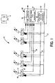
- FIG. 1 is a schematic block diagram of an antenna array transceiver 10, according to an embodiment of the present invention.
- the transceiver 10 includes an array of antennas 12 that transmit to and receive signals from a satellite 14. The satellite 14 then rebroadcasts the signal to another satellite and/or to an Earth based receiver that the transceiver 10 is in communication with.
- Each antenna 12 includes a transmitter 18 and a receiver 20. Each combination of antenna 12, transmitter 18 and receiver 20 is a separate channel of the transceiver 10.
- the antennas 12 are positioned on the Earth at random locations at a communications site. Each antenna 12 transmits and receives the same data so that the combination of all the transmissions and receptions provides enough power for the necessary or required bandwidth for a particular application. The number of antennas 12 for a particular application would be determined by the bandwidth required in combination with the actual size of each antenna 12.
- the phase relationship and the bit alignment relationship between the various signals transmitted by the antennas 12 are aligned by employing a unique calibration signal for each antenna 12 that is transmitted in combination with the desired data.
- Each calibration signal includes its own code so that the separate signals from each of the antennas 12 can be distinguished from each other.
- the calibration signal can be a binary pseudo-random sequence waveform that is transmitted at very low power and a low temporal duty cycle.
- the calibration signals transmitted by the separate antennas 12 are coded by a spread spectrum code.
- the combined calibration signal and data signal are sent to the several transmitters 18 for each channel on line 22.
- the calibration signal is modulated onto the same radio frequency carrier as the data signal so that the phase of the calibration signal and the phase of the data signal are locked together.
- Each of the receivers 20 receives all of the coded calibration signals transmitted by all of the antennas 12.
- Each of the calibration signals from each of the receivers 20 is sent to a calibration phase/delay error measurement system 24 on lines 26 within a processor 28.
- One of the channels is designated a reference channel, and is the channel with the longest round trip time to and from the satellite 14 .
- the measurement system 24 uses the calibration signals received by the reference channel to separate and identify the signals by their codes. In other words, the calibration signals from the receiver 20 of the reference antenna are used by the measurement system 24 to determine the phase relationship between the carrier frequency of the reference channel and the carrier frequency of all of the other channels. Additionally, the measurement system 24 measures the time delay between the calibration signal for the reference channel and the calibration signal from the other channels.
- phase/delay correction computation system 32 that determines how much the transmissions from the various antennas 12 must be delayed in time and changed in phase relative to the transmission from the reference antenna so that the carrier waves from each antenna 12 arrive at the satellite 14 in phase, and all of the data is aligned in time. This information from the computation system 32 is applied to the transmitters 18 on line 34. Because the data signal is phase locked to the calibration signal, the corrected calibration signal causes the data signal from each antenna 12 to also be in phase and aligned in time.
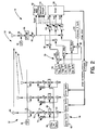
- FIG. 2 is a schematic block diagram of a communications system 50 showing a laboratory depiction of the phase alignment technique to align the transmitted signals of the invention described above.
- the system 50 includes a transmitter 52 and a receiver 54.
- the transmitter 52 includes three separate channels 56, where each channel transmits a separate coded calibration signal. Because each channel 56 is the same, only one channel will be described with the understanding that the other two channels operate in the same manner.
- the channel that is described is the reference channel.
- the second split carrier signal from the divider 64 is applied to the summer 70 through an attenuator 72 as an unmodulated signal.
- the unmodulated signal represents the data signal even though it is not modulated with actual data in this laboratory example. It is not necessary to transmit data in this example because it is the calibration signal that is the focus.
- the attenuator 72 and the amplifier 74 combine to set the relative power between the data signal and the coded signal so that they have different powers and do not interfere with each other.
- the summer 70 combines the data signal and the calibration signal so that they are locked in phase.
- the summed signal from the summer 70 is applied to a multiplier 76 along with a high frequency signal from a local oscillator 78.
- the local oscillator signal upconverts the signal to be transmitted by the antenna 60 and generates, for example, a 12 GHz +/-70 MHz signal.
- Each channel 56 generates a separately coded signal that is transmitted at the same carrier frequency, where the data signal is phase locked to the calibration signal.
- the amplified intermediate frequency signal is also sent to three separate channels 94 in the receiver 54 to separate the codes for each of the channels 56.
- Each channel 94 operates in the same manner, and therefore only one channel will be described with the understanding that the other two channels operate in the same manner.
- a separate one of the codes is output to an oscilloscope 108.
- the oscilloscope 108 displays the carriers of the various codes, and provides the phase difference between them.
- the phase difference between the first coded signal and the second coded signal is supplied to a computer 112, which provides a command to the carrier synthesizer 62 in the second channel in the transmitter 52, and the phase difference between the first coded signal and the third coded signal is applied to the carrier synthesizer 62 in the third channel of the transmitter 52 to provide the phase relationship correction.
- a spectrum analyzer 110 is also provided to display the power of the received and combined data signal.
- FIG. 3 is a functional block diagram 120 showing how the signals to be transmitted are aligned in phase and are timed relative to each other in the manner described above.
- the block diagram 120 includes a transmission control system 122 for an n channel that represents any channel that is not the reference channel.
- the calibration signal generated as discussed above, in this channel is applied to a delay device 124 for bit alignment purposes, as will be discussed below. Because the calibration signal is digital, it is converted to an analog signal by a digital-to-analog (D/A) converter 126 for transmission. Likewise, the digital data signal to be transmitted is sent through a delay device 128, and then to a digital-to-analog converter 130 to be converted to an analog signal for transmission.
- D/A digital-to-analog
- the RF transmission from the transmission control system 122 is sent to the satellite 14. All of the antennas 12 receive all of the calibration signals from all of the channels. In the reference channel, the antenna 12 sends the received signals to an amplifier 144 in an error measurement system 146 in the receiver 20. A downconverter 148 converts the high frequency carrier signal to a suitable IF for processing. A despreader 150 is provided to decode the reference channel signal and a despreader 152 is provided to decode the n channel signal. The despreaders 150 and 152 each provide a frame sync output that is indicative of the timing of the data and calibration code of the received signal for the reference channel and the n channel.
- the frame sync signals are received by a time difference system 154 that acts to identify the relative alignment between the frame sync signals.
- the output of the time difference system 154 is a signal indicative of the alignment between the data and calibration code in the n channel and the data and calibration code in the reference channel. The alignment between the signal for each channel and the reference channel is performed in this manner.
- the despreaders 150 and 152 decode the signals by removing the digital code for that channel and leaving the IF carrier for a particular signal. In other words, the despreader 150 receives all of the coded signals for all the channels, but only outputs the carrier signal for the particular code associated with the reference channel because the code in the despreader 150 only selects the code for that channel.
- the despreader 152 does the same for the n channel.
- the despreaders 150 and 152 separate the carrier signals for the particular code into in-phase and quadrature-phase signals.
- the in-phase signals from the despreaders 150 and 152 are sent to a multiplier 156, and the quadrature-phase signals from the despreaders 150 and 152 are sent to a multiplier 158.
- the in-phase and quadrature-phase signals from the despreaders 150 and 152 are also applied to multipliers 164 and 166.
- the multiplied signals from the multipliers 164 and 166 are then applied to a summer 168 that adds the signals to provide the cosine of the phase difference between the signals.
- An accumulator 170 accumulates the added cosines and provides a lock indicator output indicative of when the phase error between the reference channel and the n channel is reduced to zero, indicating the signals are in-phase.
- Both the delay error signal from the difference system 154 and the phase error signal from the accumulator 162 are applied to a correction computation system 172 that determines the amount of delay needed to align the n channel with the reference channel, and the phase adjustment needed to cause the n channel carrier signal to be in phase with the reference channel carrier signal.
- a delay correction signal from the correction computation system 172 is then sent to the delay devices 124 and 128 to delay the calibration and data signals of the n channel and align them with the calibration signal and data signals in the reference channel.
- a phase correction signal is sent to the conversion system 138 to provide a phase correction to the n channel carrier signal.
- the frequency f plus the phase error k ⁇ 1n between the n channel and the reference channel is applied to a digital receiver 196 in the n channel so that the phase of the low frequency narrow band signal in the digital receiver 196 is matched to the frequency in the digital receiver 192.
- the time difference signal t 1n is applied to a FIFO register 198 in the n channel to provide a delay to the received signal to align the n channel with the reference channel 1. Therefore, the low frequency signal from the digital receiver 192 is aligned in time and phase with the signal from the digital receiver 192. This process is performed for the other channels relative to the reference channel 1.
- All of the aligned signals from all of the channels 1 - n are sent to a combiner 200 that adds the signals to a single signal representative of the received signal.
- the combined signal is then sent to a digital demodulator where the digital low frequency carrier wave is removed and the digital data is identified.
- the round trip time T RT of the transmission of the calibration signal from the antennas 12 to the satellite 14 and then from the satellite 14 to the antennas 12 is typically on the order of one-quarter of a second.
- the phase and time differences between channels change sufficiently slowly that this round trip time does not affect the measurement and correction process as just described.
- the communication site is on a ship or the like, where the relative orientation between the antennas 12 and the satellite 14 may change significantly during the transmission round trip time of the calibration signal, relative phase changes due to the movement of the antennas 12 relative to the satellite 14 and each other need to be compensated for during this time.
- FIG. 5 shows an example of a system architecture 210 for a particular implementation of the system described above.
- the architecture 210 includes an antenna platform 212 that includes an antenna feed 214 connected to the antenna 12.
- the received signals from the antenna 12 go through a transmission reject system 216, a low noise amplifier (LNA) 218, and are downconverted by a downconverter 220 to generate the intermediate frequency received signal.
- the signals to be transmitted are sent to an up-converter 222 to upconvert the signal to a higher frequency, and then to a high power amplifier (HPA) 224, through a receiver reject system 226 and then to the antenna feed 214.
- a frequency reference input signal is applied to the downconverter 220 and the upconverter 222 from a system clock 230 to lock the signals to a particular frequency.
- the system clock 230 in a control platform 232, provides timing for the various operations.
- a modem 234 is provided for each channel, where the modem 234 includes everything in the error measurement system 146 after the downconverter 148, and also includes the converter 186, the analog-to-digital converter 188, the FIFO register 190, and the digital receiver 192.
- a digital summer 236 represents the combiner 202.
- a track processing system 238 includes the phase accumulator 204, the delay-phase error system 194 and the correction computation system 172.
- a digital demodulator 240 demodulates the digital data received from the summer 236.
Landscapes
- Engineering & Computer Science (AREA)
- Computer Networks & Wireless Communication (AREA)
- Radio Relay Systems (AREA)
- Variable-Direction Aerials And Aerial Arrays (AREA)
- Radio Transmission System (AREA)
Description
- This invention relates generally to a communications array transceiver and, more particularly, to a transceiver for a satellite communications system that employs an array of small, readily transportable antennas that transmit signals that are in phase and aligned in time with each other.
- The military requires robust, reliable and increasingly wideband communications systems to provide for the rapid collection and dissemination of intelligence data and tactical command and control information. There is a great tactical value in providing timely data to, and reports from, mobile units in the field that may be in a hostile environment. Satisfaction of this need requires that communications links be established quickly between the field unit and a remote, sometimes transcontinental, site. It has been recognized that communications by satellite provides the required access in this type of environment.
- Modern strategic and tactical communications of this type typically require wide bandwidth communications, for example 40 megabits per second. A certain amount of energy is required for each bit that is to be transmitted. The more bits transmitted per second, the more energy is required per unit time, and thus the more power for the transmission is required. Similarly, a certain amount of energy per bit is required to receive a communication, and wider bandwidth communications require more signal power to be received. The system's transmission power requirements can be reduced and its receiving power collection capacity can be increased by increasing the antenna gain, which is achieved by increasing the size of the antenna. Therefore, large reception and transmission apertures are usually necessary to supply the gain to handle wide bandwidth signals. For example, to transmit 40 megabits per second in the Ku frequency band, it is desirable to have an antenna that is about 10 meters in diameter.
- State of the art satellite communications systems are almost exclusively constructed of a single antenna that has a large aperture and a corresponding large high power amplifier to achieve high sensitivity and high equivalent isotropic radiated power (EIRP) for wide bandwidth communications. Typically, the combination of the large size of the aperture and the amplifier provide a communications system that is unwieldy for rapid deployment in unfriendly terrains. It is possible to transmit the higher data rate signals at lower power by combining identical transmissions from a plurality of smaller, more readily deployable antennas. However, in order to provide such a system, the transmitted bits from each separate antenna must be aligned in time with each other, and the radio frequency carrier transmitted by each antenna must be in phase with each other.
- It is known to use phased array antennas to improve sensitivity and EIRP by phasing transmitted and/or received signals. The phased array antennas are typically constructed of a fixed, permanent, rigid physical configuration with closely spaced antenna elements that do not require or implement delay compensations. A variation of this type of antenna is a phased array design that implements "true time delay" for each element as a means of adjusting the phase of each element. Known designs of this type, however, require and implement delays that have a known relationship from element to element and do not require and do not implement delays that are arbitrary as a result of an arbitrary physical disposition of the elements.
- One known commercial satellite communications system that employs more than one antenna is the TACSTAR MK-II, available from Datron/Transco Inc. This system performs phase combining with two independent antenna elements. In this design, the antenna operates only in the receive mode with two closely spaced antenna elements for narrowband signals that do not require delay compensation.
-
US 5,809,087 discloses a coherent architecture for remotely calibrating a coherent communications system having a plurality of antennas by a system reference signal and a system calibration signal, comprising a first antenna for transmitting the system reference signal to a remote receiver, a second antenna for transmitting the system calibration signal to the remote receiver, and a third antenna for receiving said system reference and system calibration signals at the remote receiver. The transmit subsystems derive multiple signals, i.e. calibration and reference, that are phase-locked to a common oscillator with a defined frequency and phase. All the receive subsystems derive a signal locked in frequency and phase to the uncoded calibration signal without extra amplitude and phase shift. - What is needed is a satellite communications system that provides transmission and reception of wideband signals, and includes antennas and corresponding equipment that is easily deployable, rugged, reliable and secure, It is therefore an object of the present invention to provide such a communications system.
- The object of the present invention is achieved by a transceiver according to
claim 1, a satellite communications system according to claim 11 and a method according toclaim 18. - In accordance with the teachings of the present invention, a satellite communications system is disclosed that employs an array of separate and easily deployable antennas for transmission and reception purposes to accommodate high data rate transmissions. The antennas can be deployed randomly at a communications site, and are physically separated. Each antenna transmits and receives the same data. A coded signal is used to identify the transmission from each antenna for calibration purposes to align the bits transmitted by each antenna in time and provide phase matching for the carrier wave of each antenna signal. The coded signals are used to compare the phase and timing relationship between each antenna signal and a reference antenna signal when the reference antenna receives all the coded signals for all of the antennas. Correction computations are performed and specialized phase and data alignment systems are employed to delay the various transmitted signals relative to the reference antenna to provide the desired alignment. Additionally, phase and timing systems are used to determine and correct the phase and data timing variations between the data received by the antennas so that they can be combined and processed.
- Further objects, features and advantages of the present invention will become apparent from a consideration of the following description and the appended claims when taken in conjunction with the accompanying drawings.
-
-
Figure 1 is a functional block diagram of a transceiver array for a satellite communications system, according to an embodiment of the present invention; -
Figure 2 is a functional block diagram of a communications system incorporating a transceiver array of the invention used for laboratory verification; -
Figure 3 is a functional block diagram showing a transmission control and error estimation system for a channel of the communications system shown inFigure 1 ; -
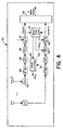
Figure 4 is a functional block diagram showing a receiver combining method of the communications system shown inFigure 1 ; and -
Figure 5 is a block diagram of a system architecture for the communications system shown inFigure 1 . - The following discussion of the preferred embodiments directed to a satellite communications system including an array of antennas is merely exemplary in nature, and is in no way intended to limit the invention or its applications or uses.
-
Figure 1 is a schematic block diagram of anantenna array transceiver 10, according to an embodiment of the present invention. Thetransceiver 10 includes an array ofantennas 12 that transmit to and receive signals from asatellite 14. Thesatellite 14 then rebroadcasts the signal to another satellite and/or to an Earth based receiver that thetransceiver 10 is in communication with. Eachantenna 12 includes atransmitter 18 and areceiver 20. Each combination ofantenna 12,transmitter 18 andreceiver 20 is a separate channel of thetransceiver 10. Theantennas 12 are positioned on the Earth at random locations at a communications site. Eachantenna 12 transmits and receives the same data so that the combination of all the transmissions and receptions provides enough power for the necessary or required bandwidth for a particular application. The number ofantennas 12 for a particular application would be determined by the bandwidth required in combination with the actual size of eachantenna 12. - Because the location of the
antennas 12 on the Earth relative to thesatellite 14 is arbitrary, a phase and bit alignment correction needs to be made to insure that the carrier signal associated with the transmitted signals from theantennas 12 arrive at thesatellite 14 in phase with each other, and the bits being transmitted by each channel arrive at thesatellite 14 at the same time. According to the invention, the phase relationship and the bit alignment relationship between the various signals transmitted by theantennas 12 are aligned by employing a unique calibration signal for eachantenna 12 that is transmitted in combination with the desired data. Each calibration signal includes its own code so that the separate signals from each of theantennas 12 can be distinguished from each other. The calibration signal can be a binary pseudo-random sequence waveform that is transmitted at very low power and a low temporal duty cycle. In one embodiment, the calibration signals transmitted by theseparate antennas 12 are coded by a spread spectrum code. The combined calibration signal and data signal are sent to theseveral transmitters 18 for each channel online 22. The calibration signal is modulated onto the same radio frequency carrier as the data signal so that the phase of the calibration signal and the phase of the data signal are locked together. - The combination of the data signal and the calibration signal are transmitted by the
antennas 12 and received by thesatellite 14. Thesatellite 14 rebroadcasts the combined signal, at a different carrier frequency, to be received by each of theantennas 12. Because the calibration signal is transmitted at a much lower power than the data signal, it does not interfere with the data signal. - Each of the
receivers 20 receives all of the coded calibration signals transmitted by all of theantennas 12. Each of the calibration signals from each of thereceivers 20 is sent to a calibration phase/delayerror measurement system 24 onlines 26 within aprocessor 28. One of the channels is designated a reference channel, and is the channel with the longest round trip time to and from thesatellite 14 . Themeasurement system 24 uses the calibration signals received by the reference channel to separate and identify the signals by their codes. In other words, the calibration signals from thereceiver 20 of the reference antenna are used by themeasurement system 24 to determine the phase relationship between the carrier frequency of the reference channel and the carrier frequency of all of the other channels. Additionally, themeasurement system 24 measures the time delay between the calibration signal for the reference channel and the calibration signal from the other channels. - The measurement of the phase and delay between the signal from the reference channel and the signal from each of the other channels identified by the
measurement system 24 is then applied to a phase/delaycorrection computation system 32 that determines how much the transmissions from thevarious antennas 12 must be delayed in time and changed in phase relative to the transmission from the reference antenna so that the carrier waves from eachantenna 12 arrive at thesatellite 14 in phase, and all of the data is aligned in time. This information from thecomputation system 32 is applied to thetransmitters 18 online 34. Because the data signal is phase locked to the calibration signal, the corrected calibration signal causes the data signal from eachantenna 12 to also be in phase and aligned in time. - Phase and data alignment must also be provided for the signals received by the
antennas 12 from the remote communications site. To provide this alignment, each of the received signals from thereceivers 20 are also sent to areceiver combining system 38. The combiningsystem 38 processes the various signals so that the carriers are aligned in phase, and data aligned in time, and sums the aligned signals together. Various receiver combining schemes are known in the art that provide this type of function. In one particular scheme, the various signals received by theantennas 12 are cross-correlated relative to each other. The cross correlation between the received signals gives the phase difference between the signals and their relative delay. -
Figure 2 is a schematic block diagram of acommunications system 50 showing a laboratory depiction of the phase alignment technique to align the transmitted signals of the invention described above. Thesystem 50 includes atransmitter 52 and areceiver 54. Thetransmitter 52 includes threeseparate channels 56, where each channel transmits a separate coded calibration signal. Because eachchannel 56 is the same, only one channel will be described with the understanding that the other two channels operate in the same manner. The channel that is described is the reference channel. - Each
channel 56 includes anantenna 60 for transmitting the combined calibration and data signal. Eachchannel 56 also includes acarrier synthesizer 62 that generates a carrier signal, 70 MHz in this example. The carrier signal is sent to adivider 64 that divides the signal into first and second paths. The first path is connected to a linear recursive sequencerandom number generator 66. Thegenerator 66 provides a predetermined sequence of zero and one bits that defines the calibration code for that channel. The calibration code modulates the carrier frequency from thesynthesizer 62. Thegenerator 66 also receives a signal from achip reference synthesizer 68. Thechip reference synthesizer 68 is a clock input to thegenerator 66 that determines the rate at which the zero and one bits are generated in thegenerator 66. The coded modulated carrier wave from thegenerator 66 is applied to asummer 70 through anamplifier 74. - The second split carrier signal from the
divider 64 is applied to thesummer 70 through anattenuator 72 as an unmodulated signal. The unmodulated signal represents the data signal even though it is not modulated with actual data in this laboratory example. It is not necessary to transmit data in this example because it is the calibration signal that is the focus. Theattenuator 72 and theamplifier 74 combine to set the relative power between the data signal and the coded signal so that they have different powers and do not interfere with each other. Thesummer 70 combines the data signal and the calibration signal so that they are locked in phase. The summed signal from thesummer 70 is applied to amultiplier 76 along with a high frequency signal from alocal oscillator 78. The local oscillator signal upconverts the signal to be transmitted by theantenna 60 and generates, for example, a 12 GHz +/-70 MHz signal. Eachchannel 56 generates a separately coded signal that is transmitted at the same carrier frequency, where the data signal is phase locked to the calibration signal. - The transmitted signals from the
antennas 60 for eachchannel 56 are received by areceiver antenna 82 in thereceiver 54. Theantenna 82 represents any one of theantennas 12 and is preferably the reference channel. The signals received by theantenna 82 are multiplied with a local oscillator signal from alocal oscillator 84 in amultiplier 86 to provide a difference signal that will be used as an intermediate frequency for downconversion purposes. In this example, the frequency of thelocal oscillator 84 is 11,860 GHz to provide the intermediate frequency of about 70 MHz, as used in thetransmitter 52. A low pass filter/bandpass filter 88 filters out the sum signal and the harmonics from themultiplier 86, and passes the intermediate frequency signal through to be amplified by anamplifier 90. The amplified intermediate signal is sent to apower meter 92 to provide a measurement of the received power. - The amplified intermediate frequency signal is also sent to three
separate channels 94 in thereceiver 54 to separate the codes for each of thechannels 56. Eachchannel 94 operates in the same manner, and therefore only one channel will be described with the understanding that the other two channels operate in the same manner. - The signal from the
bandpass filter 88 includes all three of the coded calibration signals from thechannels 56. This signal is applied to amultiplier 96 in eachchannel 94. Each code that was generated in thetransmitter 52 is also reconstructed in thereceiver 54. To accomplish this, acode generator 100 is used to generate the codes, and is similar to thegenerator 66. Thegenerator 100 receives a despread intermediate frequency signal, for example 70 MHz, from adespreader synthesizer 102, that is modulated by the particular zero and one bit code in thecode generator 100. Adivider 98 is used to divide the signal from thesynthesizer 102 so that eachchannel 94 receives the same carrier frequency. Achip despreader synthesizer 104 provides the clock input to thecode generator 100 to provide the rate at which the ones and zeros are generated. The coded signal is thus generated in the same manner as in thetransmitter 52. The coded signal at the intermediate frequency from thecode generator 100 is then applied to themultiplier 96 to be multiplied with the intermediate frequency signal received by theantenna 82. By multiplying the received calibration signal with the locally generated coded signal, the like codes cancel out. Because the signal from theantenna 82 includes all three codes, only the particular code generated by thecode generator 100 is cancelled. The remaining two codes are still present from the output of themultiplier 96. This signal is filtered by a lowpass filter (LPF) 106 that only passes the low frequency carrier of the signal. Thus, only the carrier for the first calibration signal is passed by theLPF 106. - Therefore, for each
channel 94, a separate one of the codes is output to anoscilloscope 108. Theoscilloscope 108 displays the carriers of the various codes, and provides the phase difference between them. The phase difference between the first coded signal and the second coded signal is supplied to acomputer 112, which provides a command to thecarrier synthesizer 62 in the second channel in thetransmitter 52, and the phase difference between the first coded signal and the third coded signal is applied to thecarrier synthesizer 62 in the third channel of thetransmitter 52 to provide the phase relationship correction. Aspectrum analyzer 110 is also provided to display the power of the received and combined data signal. -
Figure 3 is a functional block diagram 120 showing how the signals to be transmitted are aligned in phase and are timed relative to each other in the manner described above. The block diagram 120 includes atransmission control system 122 for an n channel that represents any channel that is not the reference channel. The calibration signal, generated as discussed above, in this channel is applied to adelay device 124 for bit alignment purposes, as will be discussed below. Because the calibration signal is digital, it is converted to an analog signal by a digital-to-analog (D/A)converter 126 for transmission. Likewise, the digital data signal to be transmitted is sent through adelay device 128, and then to a digital-to-analog converter 130 to be converted to an analog signal for transmission.Amplifiers summer 136 for transmission. The combined calibration signal and data signal is applied to a base-band (BB) to IFconversion system 138 that modulates the base-band data and the calibration signal onto an IF carrier wave. The intermediate frequency carrier signal is then upconverted to a high frequency (12 GHz) by anupconverter 140 suitable for transmission. - The RF transmission from the
transmission control system 122 is sent to thesatellite 14. All of theantennas 12 receive all of the calibration signals from all of the channels. In the reference channel, theantenna 12 sends the received signals to anamplifier 144 in anerror measurement system 146 in thereceiver 20. Adownconverter 148 converts the high frequency carrier signal to a suitable IF for processing. Adespreader 150 is provided to decode the reference channel signal and adespreader 152 is provided to decode the n channel signal. Thedespreaders time difference system 154 that acts to identify the relative alignment between the frame sync signals. The output of thetime difference system 154 is a signal indicative of the alignment between the data and calibration code in the n channel and the data and calibration code in the reference channel. The alignment between the signal for each channel and the reference channel is performed in this manner. - The
despreaders despreader 150 receives all of the coded signals for all the channels, but only outputs the carrier signal for the particular code associated with the reference channel because the code in thedespreader 150 only selects the code for that channel. Thedespreader 152 does the same for the n channel. Thedespreaders despreaders multiplier 156, and the quadrature-phase signals from thedespreaders multiplier 158. The multiplied in-phase and quadrature-phase signals from the reference channel and the n channel are then applied to asummer 160 that subtracts the signals to generate a difference signal that gives the sine of the phase difference between the carrier signals. The difference signal is sent to anaccumulator 162 that accumulates the sine difference to provide a phase error output of the difference in phase of the carrier signals for the reference channel and the n channel. - The in-phase and quadrature-phase signals from the
despreaders multipliers multipliers summer 168 that adds the signals to provide the cosine of the phase difference between the signals. Anaccumulator 170 accumulates the added cosines and provides a lock indicator output indicative of when the phase error between the reference channel and the n channel is reduced to zero, indicating the signals are in-phase. - Both the delay error signal from the
difference system 154 and the phase error signal from theaccumulator 162 are applied to acorrection computation system 172 that determines the amount of delay needed to align the n channel with the reference channel, and the phase adjustment needed to cause the n channel carrier signal to be in phase with the reference channel carrier signal. A delay correction signal from thecorrection computation system 172 is then sent to thedelay devices conversion system 138 to provide a phase correction to the n channel carrier signal. Therefore, the RF signal transmitted by theantenna 12 in the n channel is aligned in time and in phase, as it is seen by thesatellite 14, with the RF signal transmitted by the reference channel. This delay and phase adjustment process is done for all the channels relative to the reference channel so that all of the channels are aligned in time and in phase with the reference channel, and thus with each other. -
Figure 4 is a functional block diagram 180 showing how signals received from a remote communications site are aligned in phase and in time, and combined, for all the channels. Each one of the channels is represented inFigure 4 , including thereference channel 1. The receiver functions of thereference channel 1 will be discussed below, with the understanding that the other channels receive and process the signals in the same manner. Eachantenna 12 receives the same signals from thesatellite 14. The signals received by theantenna 12 in the reference channel are downconverted by adownconverter 184 to an intermediate frequency, and then from an intermediate frequency to base-band by aconverter 186. The base-band signal is then converted to a digital signal by an analog-to-digital converter 188. The digital signal is then sent to a first-in first-out (FIFO)delay register 190. The downconverted, digital signal from theFIFO register 190 is then sent to adigital receiver 192 that provides digital filtering around an optimum band and further downconversion by an applied frequency f. The digital representation of the signal allows for frequency phase control. - This downconversion and digitizing process as just described is provided for all of the n channels. The digitized signal for each channel is then sent to a delay/
phase error system 194. Theerror system 194 separately computes the delay difference and the phase difference between the digital reference channel signal and the digital signal for each of the other channels. This delay and phase error determination can be done in any number of different ways known to those skilled in the art. One example is a cross-correlation technique. The delay t1n and the phase error kφ1n computed by thesystem 194 for each channel are applied to the delay register and the digital receiver, respectively, in each of the channels to align them with the reference channel. The frequency f plus the phase error kφ1n between the n channel and the reference channel is applied to adigital receiver 196 in the n channel so that the phase of the low frequency narrow band signal in thedigital receiver 196 is matched to the frequency in thedigital receiver 192. Likewise, the time difference signal t1n is applied to aFIFO register 198 in the n channel to provide a delay to the received signal to align the n channel with thereference channel 1. Therefore, the low frequency signal from thedigital receiver 192 is aligned in time and phase with the signal from thedigital receiver 192. This process is performed for the other channels relative to thereference channel 1. - All of the aligned signals from all of the channels 1 - n are sent to a combiner 200 that adds the signals to a single signal representative of the received signal. The combined signal is then sent to a digital demodulator where the digital low frequency carrier wave is removed and the digital data is identified.
- The round trip time TRT of the transmission of the calibration signal from the
antennas 12 to thesatellite 14 and then from thesatellite 14 to theantennas 12 is typically on the order of one-quarter of a second. For land based deployment of the array transceiver, the phase and time differences between channels change sufficiently slowly that this round trip time does not affect the measurement and correction process as just described. However, if the communication site is on a ship or the like, where the relative orientation between theantennas 12 and thesatellite 14 may change significantly during the transmission round trip time of the calibration signal, relative phase changes due to the movement of theantennas 12 relative to thesatellite 14 and each other need to be compensated for during this time. - Therefore, an output signal from the
system 194 is provided that is representative of the continually measured phase difference between the reference channel and each n channel, and is sent to aphase accumulator 204. Additionally, the round trip time TRT is applied to thephase accumulator 204. Thephase accumulator 204 continually adds up the phase differences for each of the channels for the round trip time, and outputs the phase change as Δφ ln to thecorrection computation system 172. Thecorrection computation system 172 computes the phase correction at the transmission frequency that compensates for the short term phase change Δφ ln that was measured at the receiving frequency. The short term phase change due to transceiver motion is thereby accounted for. -
Figure 5 shows an example of asystem architecture 210 for a particular implementation of the system described above. Thearchitecture 210 includes anantenna platform 212 that includes anantenna feed 214 connected to theantenna 12. The received signals from theantenna 12 go through atransmission reject system 216, a low noise amplifier (LNA) 218, and are downconverted by adownconverter 220 to generate the intermediate frequency received signal. The signals to be transmitted are sent to an up-converter 222 to upconvert the signal to a higher frequency, and then to a high power amplifier (HPA) 224, through areceiver reject system 226 and then to theantenna feed 214. A frequency reference input signal is applied to thedownconverter 220 and theupconverter 222 from asystem clock 230 to lock the signals to a particular frequency. - The
system clock 230, in acontrol platform 232, provides timing for the various operations. Amodem 234 is provided for each channel, where themodem 234 includes everything in theerror measurement system 146 after thedownconverter 148, and also includes theconverter 186, the analog-to-digital converter 188, theFIFO register 190, and thedigital receiver 192. Adigital summer 236 represents thecombiner 202. Atrack processing system 238 includes thephase accumulator 204, the delay-phase error system 194 and thecorrection computation system 172. Adigital demodulator 240 demodulates the digital data received from thesummer 236.
Claims (21)
- A satellite communications systems for transmitting signals between Earth based communications sites and a satellite, one of the communication sites including a transceiver (10) comprising:an array of antennas (12), each of the antennas (12) being randomly positioned relative to each other, each of the antennas (12) identifying a separate channel of the transceiver (10) where one of the channels is a reference channel, each channel transmitting signals on a common carrier frequency and including the same data signal;a code generation system (32), said code generation system (32) generating a unique calibration signal for each channel, each channel transmitting its calibration signal phase locked to the data signal;a satellite (14) for receiving the transmitted signals from said communication site from each of the channels and retransmitting the transmitted signal back to said communication site;wherein said retransmitted signal is received by the antennas (12) from said communication site; andan alignment error system (24), said alignment error system (24) generating a transmit alignment error signal that identifies an alignment error between the calibration signal transmitted by each channel and received by the satellite and the calibration signal transmitted by the reference channel and received by the satellite;a phase error determination system (24), said phase error determination system (24) determining a phase error signal that is the difference between the phase of the carrier signal transmitted by each channel and the phase of the carrier signal transmitted by the reference channel; anda correction system (32) including a plurality of delay devices, said correction system (32) generating a time correction for each transmission channel that is applied to a delay device in that transmission channel (34) to align the calibration signal transmitted by each channel and received by the satellite with the calibration signal transmitted by the reference channel and by the satellite such that the corresponding phase locked loop data signals are aligned.
- The satellite communications systems of Claim 1, further comprising a receiver combining system (38), said receiver combining system (38) determining a bit timing difference and a phase difference between data signals received by the reference channel and data signals received by the other channels, said combining system providing a receive alignment error signal for each channel to align the received data signals in time and in phase.
- The satellite communications systems of Claim 1, wherein the alignment error system (24) and the phase error system (24) include a decoder (150, 152) for each channel, each decoder (150, 152) identifying the code for its channel from the codes of all of the channels.
- The satellite communications systems of Claim 3, further comprising a time difference system (154), said time difference system (154) being responsive to a frame sync signal from each decoder (150, 152) that identifies a position of the calibration signal in time, said time difference system (154) outputting a delay error for each channel that is representative of the delay necessary to align the calibration signal for each channel with the calibration signal for the reference channel.
- The satellite communications systems of Claim 3, wherein each decoder (150, 152) generates in-phase and quadrature-phase signals of the carrier signal transmitted by each channel, and wherein the phase error system includes a plurality of multipliers (164, 166), wherein a pair of multipliers (164, 166) multiply the in-phase and quadrature-phase signals for each channel and the reference channel.
- The satellite communications systems of Claim 5, wherein the phase error system further includes a plurality of summers (70), each summer (70) generating a difference signal between the multiplied in-phase and quadrature-phase signals for each channel and the reference channel, said phase error system further comprising a plurality of accumulators (170), wherein each accumulator (170) receives a difference signal from a summer (70) and generates the phase error signal.
- The satellite communications systems of Claim 1, further comprising a receiver combining system (38) that determines a bit timing difference and a phase difference between the signals received by the reference channel and the signals received by the other channels, said combining system (38) providing a bit time aligning signal and a phase correction signal for each channel.
- The satellite communications systems of Claim 7, wherein each channel includes a delay device (190) and a digital receiver (192), said delay device (190) receiving the time aligning signal to delay the received signals a predetermined amount and said digital receiver (192) receiving the phase correction signal to phase align the received signals.
- The satellite communications systems of Claim 7, further comprising a phase accumulator (170), said phase accumulator (170) being responsive to the phase difference from the combining system (38) and a round trip time signal indicative of a round trip time between the transceiver (10) and a satellite (14), said accumulator (170) outputting a phase signal to the correction system (32).
- The satellite communications systems of Claim 7, wherein the receiver (192) combining system (38) includes a digital combiner (200) that combines the aligned signals received by each channel to a single digital output signal.
- A transceiver for the satellite communications systems of Claim 1, said transceiver comprising:an array of antennas (12), each of the antennas being randomly positioned relative to each other, each of the antennas (12) identifying a separate channel of the transceiver (10) where one of the channels is a reference channel, each channel transmitting signals on a common carrier signal and including the same data signal;a code generation system (32), said code generation system (32) generating a unique calibration signal for each channel, each channel transmitting its calibration signal phase locked to the data signal;
an alignment error system (24), said alignment error system (24) generating a transmit alignment error signal that identifies an alignment error between the calibration signal transmitted by each channel and the calibration signal transmitted by the reference channel;
a phase error determination system (24), said phase error determination system (24) determining a phase error signal that is the difference between the phase of the carrier signal transmitted by each channel and the phase of the carrier signal transmitted by the reference channel;
a correction system (32) including a plurality of delay devices, said correction system (32) generating a time correction for each transmission channel that is applied with a delay device in that transmission channel (34) to the phase locked calibration and data signals. - The transceiver of Claim 11, wherein the alignment error system (24) and the phase error system include a decoder (150, 152) for each channel, each decoder (150, 152) identifying the code for its channel from the codes of all of the channels.
- The transceiver of Claim 12, further comprising a time difference system (154), said time difference system (154) being responsive to a frame sync signal from each decoder (150, 152) that identifies a position of the calibration signal in time, said time difference system (154) outputting a delay error for each channel that is representative of the delay necessary to align the calibration signal for each channel with the calibration signal for the reference channel.
- The transceiver of Claim 12, wherein each decoder (150, 152) generates in-phase and quadrature-phase signals of the carrier signal transmitted by each channel and wherein the phase error system includes a plurality of multipliers (164, 166), wherein a pair of multipliers (164, 166) multiply the in-phase and quadrature-phase signals for each channel and the reference channel.
- The transceiver of Claim 14, wherein the phase error system further includes a plurality of summers (70), each summer (70) generating a difference signal between the multiplied in-phase and quadrature-phase signals for each channel and the reference channel, said phase error system further comprising a plurality of accumulators (170), wherein each accumulator (170) receives a difference signal from a summer (70) and generates the phase error signal.
- The transceiver of Claim 11, wherein each channel includes a delay device (190) and a digital receiver (192), said delay device (190) receiving the time aligning signal to delay the received signals a predetermined amount and said digital receiver (192) receiving the phase correction signal to phase align the received signals.
- The transceiver of Claim 11, further comprising a phase accumulator (170), said phase accumulator (170) being responsive to the phase difference from the combining system (38) and a round trip time signal indicative of a round trip time between the transceiver (10) and a satellite (14), said accumulation outputting a phase signal to the correction system (32).
- A method of receiving and transmitting signals, said method comprising steps of:arbitrarily arranging a plurality of antennas (12) at a communications site, each of the antennas (12) identifying a separate channel where one of the channels is a reference channel;generating a calibration signal unique to each channel;generating a data signal;transmitting signals including the calibration signals per channel and the data signal common to each of the channels from each antenna (12) using the same carrier frequency wherein each calibration signal is phase locked to the data signal in the transmit path;retransmitting at a remote site each of the calibration signals from each of the channels as a retransmitted signal on a second carrier frequency;receiving said retransmitted signal by the plurality of antennas;wherein the retransmitted signal separately identifies the calibration signal for each channel;determining an alignment error between the calibration signal for each channel and the calibration signal for the reference channel;determining a phase difference between the calibration signal for each channel and the calibration signal for the reference channel; andproviding a time and phase correction for the calibration signal and the phase locked data signal in each channel so that it is aligned with the calibration signal transmitted by the reference channel.
- The method according to Claim 18, further comprising the step of phase locking the calibration signals with a data signal transmitted by each channel.
- The method according to Claim 18, wherein the step of providing a time and phase correction includes delaying the transmission of the calibration signal in each channel so that it is aligned with the transmission of the reference channel.
- The method according to Claim 18, further comprising the step of determining a bit timing difference and a phase difference between signals received by the reference channel and signals received by the other channels, and providing a time alignment signal and a phase correction signal to align the data and carrier frequency of each signal received by each channel.
Applications Claiming Priority (2)
| Application Number | Priority Date | Filing Date | Title |
|---|---|---|---|
| US432370 | 1999-11-03 | ||
| US09/432,370 US6597730B1 (en) | 1999-11-03 | 1999-11-03 | Satellite communication array transceiver |
Publications (3)
| Publication Number | Publication Date |
|---|---|
| EP1098390A2 EP1098390A2 (en) | 2001-05-09 |
| EP1098390A3 EP1098390A3 (en) | 2003-11-12 |
| EP1098390B1 true EP1098390B1 (en) | 2011-04-27 |
Family
ID=23715866
Family Applications (1)
| Application Number | Title | Priority Date | Filing Date |
|---|---|---|---|
| EP00123562A Expired - Lifetime EP1098390B1 (en) | 1999-11-03 | 2000-10-27 | Satellite communication array transceiver |
Country Status (3)
| Country | Link |
|---|---|
| US (1) | US6597730B1 (en) |
| EP (1) | EP1098390B1 (en) |
| DE (1) | DE60045887D1 (en) |
Families Citing this family (31)
| Publication number | Priority date | Publication date | Assignee | Title |
|---|---|---|---|---|
| US6862440B2 (en) * | 2002-05-29 | 2005-03-01 | Intel Corporation | Method and system for multiple channel wireless transmitter and receiver phase and amplitude calibration |
| GB0327041D0 (en) * | 2003-11-21 | 2003-12-24 | Roke Manor Research | Apparatus and methods |
| FI20065841A0 (en) * | 2006-12-21 | 2006-12-21 | Nokia Corp | Communication method and systems |
| US8032183B2 (en) * | 2007-07-16 | 2011-10-04 | Alcatel Lucent | Architecture to support network-wide multiple-in-multiple-out wireless communication |
| US20100125347A1 (en) * | 2008-11-19 | 2010-05-20 | Harris Corporation | Model-based system calibration for control systems |
| US8170088B2 (en) * | 2008-11-19 | 2012-05-01 | Harris Corporation | Methods for determining a reference signal at any location along a transmission media |
| US7970365B2 (en) * | 2008-11-19 | 2011-06-28 | Harris Corporation | Systems and methods for compensating for transmission phasing errors in a communications system using a receive signal |
| US20100123618A1 (en) * | 2008-11-19 | 2010-05-20 | Harris Corporation | Closed loop phase control between distant points |
| US7969358B2 (en) * | 2008-11-19 | 2011-06-28 | Harris Corporation | Compensation of beamforming errors in a communications system having widely spaced antenna elements |
| US20100124263A1 (en) * | 2008-11-19 | 2010-05-20 | Harris Corporation | Systems for determining a reference signal at any location along a transmission media |
| GB2467773B (en) * | 2009-02-13 | 2012-02-01 | Socowave Technologies Ltd | Communication system, apparatus and methods for calibrating an antenna array |
| US8242951B2 (en) * | 2009-04-10 | 2012-08-14 | Honeywell International Inc. | System and method for generating a reference signal for phase calibration of a system |
| US20110319034A1 (en) * | 2010-06-28 | 2011-12-29 | Boe Eric N | Method and system for propagation time measurement and calibration using mutual coupling in a radio frequency transmit/receive system |
| US8970427B2 (en) | 2011-05-18 | 2015-03-03 | Mediatek Singapore Pte. Ltd. | Phase-arrayed device and method for calibrating the phase-arrayed device |
| US9083426B1 (en) * | 2012-02-08 | 2015-07-14 | RKF Engineering Solutions, LLC | Satellite beamforming |
| US9979084B2 (en) * | 2014-12-02 | 2018-05-22 | Raytheon Company | Satellite-based phased array calibration |
| KR20160149717A (en) * | 2015-06-19 | 2016-12-28 | 에스케이하이닉스 주식회사 | Semiconductor device and operating method thereof |
| US9642107B1 (en) * | 2016-08-01 | 2017-05-02 | Space Systems/Loral, Inc. | Multi-channel satellite calibration |
| US10593116B2 (en) | 2016-10-24 | 2020-03-17 | Snap Inc. | Augmented reality object manipulation |
| US10242503B2 (en) | 2017-01-09 | 2019-03-26 | Snap Inc. | Surface aware lens |
| US20180210628A1 (en) | 2017-01-23 | 2018-07-26 | Snap Inc. | Three-dimensional interaction system |
| CA3087814C (en) * | 2017-11-13 | 2023-06-13 | Loon Llc | Beamforming calibration |
| US10305608B1 (en) | 2017-11-13 | 2019-05-28 | Loon Llc | Beamforming calibration |
| US10305564B1 (en) | 2017-11-13 | 2019-05-28 | Loon Llc | Beamforming calibration |
| US10734721B2 (en) | 2017-11-13 | 2020-08-04 | Loon Llc | Beamforming calibration |
| US10305609B1 (en) | 2017-11-13 | 2019-05-28 | Loon Llc | Beamforming calibration |
| EP4117191A1 (en) * | 2017-12-28 | 2023-01-11 | Huawei Technologies Co., Ltd. | Apparatus and method for correcting deviation between plurality of transmission channels |
| US11030813B2 (en) | 2018-08-30 | 2021-06-08 | Snap Inc. | Video clip object tracking |
| US11176737B2 (en) | 2018-11-27 | 2021-11-16 | Snap Inc. | Textured mesh building |
| US11189098B2 (en) | 2019-06-28 | 2021-11-30 | Snap Inc. | 3D object camera customization system |
| KR20230129175A (en) | 2021-01-06 | 2023-09-06 | 비아셋, 인크 | Sparse Antenna Array Calibration |
Family Cites Families (5)
| Publication number | Priority date | Publication date | Assignee | Title |
|---|---|---|---|---|
| US5659572A (en) * | 1993-11-22 | 1997-08-19 | Interdigital Technology Corporation | Phased array spread spectrum system and method |
| US5677696A (en) * | 1995-07-07 | 1997-10-14 | General Electric Company | Method and apparatus for remotely calibrating a phased array system used for satellite communication using a unitary transform encoder |
| GB2313523B (en) * | 1996-05-23 | 2000-06-07 | Motorola Ltd | Self-calibration apparatus and method for communication device |
| US5809087A (en) * | 1996-10-25 | 1998-09-15 | General Electric Company | Coherent detection architecture for remote calibration of coherent systems |
| US6115406A (en) * | 1999-09-10 | 2000-09-05 | Interdigital Technology Corporation | Transmission using an antenna array in a CDMA communication system |
-
1999
- 1999-11-03 US US09/432,370 patent/US6597730B1/en not_active Expired - Lifetime
-
2000
- 2000-10-27 EP EP00123562A patent/EP1098390B1/en not_active Expired - Lifetime
- 2000-10-27 DE DE60045887T patent/DE60045887D1/en not_active Expired - Lifetime
Also Published As
| Publication number | Publication date |
|---|---|
| US6597730B1 (en) | 2003-07-22 |
| EP1098390A3 (en) | 2003-11-12 |
| EP1098390A2 (en) | 2001-05-09 |
| DE60045887D1 (en) | 2011-06-09 |
Similar Documents
| Publication | Publication Date | Title |
|---|---|---|
| US6597730B1 (en) | Satellite communication array transceiver | |
| US6647276B1 (en) | Antenna unit and radio base station therewith | |
| US6570527B1 (en) | Calibration of differential frequency-dependent characteristics of a radio communications system | |
| US6788948B2 (en) | Frequency dependent calibration of a wideband radio system using narrowband channels | |
| US5233626A (en) | Repeater diversity spread spectrum communication system | |
| US5859874A (en) | Multipath communication system optimizer | |
| CN101651480B (en) | Active antenna, base station, method for updating amplitude and phase, and signal processing method | |
| US7336745B2 (en) | Methods and apparatus to provide communication protection technology for satellite earthstations | |
| US7346316B1 (en) | Radio communication system, a transmitter and a receiver | |
| US6448926B1 (en) | Multi-band, multi-function integrated transceiver | |
| CA2227522C (en) | Self-calibration apparatus and method for communication device | |
| US20090103593A1 (en) | Array Antenna System and Spread Spectrum Beamformer Method | |
| EP1237291A2 (en) | Spread spectrum communication device | |
| JPH09121201A (en) | Cross polarization canceller and polarization state correction method | |
| US20020033766A1 (en) | Apparatus for receiving ranging signals | |
| US7054397B1 (en) | Mobile communication system having mobile stations and a base station | |
| WO1991005420A1 (en) | Automatic frequency control of satellite transmitted spread spectrum signals | |
| US7236778B2 (en) | System and method for testing transceivers | |
| NO320227B1 (en) | Method and apparatus for determining characteristics of components of a communication channel under load | |
| US4706093A (en) | Monopulse tracking system substantially free of externally generated noise | |
| Andrenacci et al. | A new highly spread spectrum slotted burst (H3SB) protocol for satcom applications | |
| JPS5855707B2 (en) | Diversity transmitter to mobile station | |
| Alonso et al. | Two prototypes of adaptive antenna receivers for mobile systems | |
| Harris et al. | Commercial GPS receiver susceptibility evaluation | |
| BROCKMAN et al. | Radio frequency arraying method for receivers[Patent] |
Legal Events
| Date | Code | Title | Description |
|---|---|---|---|
| PUAI | Public reference made under article 153(3) epc to a published international application that has entered the european phase |
Free format text: ORIGINAL CODE: 0009012 |
|
| AK | Designated contracting states |
Kind code of ref document: A2 Designated state(s): AT BE CH CY DE DK ES FI FR GB GR IE IT LI LU MC NL PT SE |
|
| AX | Request for extension of the european patent |
Free format text: AL;LT;LV;MK;RO;SI |
|
| PUAL | Search report despatched |
Free format text: ORIGINAL CODE: 0009013 |
|
| AK | Designated contracting states |
Kind code of ref document: A3 Designated state(s): AT BE CH CY DE DK ES FI FR GB GR IE IT LI LU MC NL PT SE |
|
| AX | Request for extension of the european patent |
Extension state: AL LT LV MK RO SI |
|
| RAP1 | Party data changed (applicant data changed or rights of an application transferred) |
Owner name: NORTHROP GRUMMAN CORPORATION |
|
| RAP1 | Party data changed (applicant data changed or rights of an application transferred) |
Owner name: NORTHROP GRUMMAN CORPORATION |
|
| 17P | Request for examination filed |
Effective date: 20040511 |
|
| AKX | Designation fees paid |
Designated state(s): DE FR GB |
|
| 17Q | First examination report despatched |
Effective date: 20050223 |
|
| GRAP | Despatch of communication of intention to grant a patent |
Free format text: ORIGINAL CODE: EPIDOSNIGR1 |
|
| GRAS | Grant fee paid |
Free format text: ORIGINAL CODE: EPIDOSNIGR3 |
|
| GRAC | Information related to communication of intention to grant a patent modified |
Free format text: ORIGINAL CODE: EPIDOSCIGR1 |
|
| GRAL | Information related to payment of fee for publishing/printing deleted |
Free format text: ORIGINAL CODE: EPIDOSDIGR3 |
|
| GRAS | Grant fee paid |
Free format text: ORIGINAL CODE: EPIDOSNIGR3 |
|
| GRAA | (expected) grant |
Free format text: ORIGINAL CODE: 0009210 |
|
| RAP1 | Party data changed (applicant data changed or rights of an application transferred) |
Owner name: NORTHROP GRUMMAN SYSTEMS CORPORATION |
|
| AK | Designated contracting states |
Kind code of ref document: B1 Designated state(s): DE FR GB |
|
| REG | Reference to a national code |
Ref country code: GB Ref legal event code: FG4D |
|
| REF | Corresponds to: |
Ref document number: 60045887 Country of ref document: DE Date of ref document: 20110609 Kind code of ref document: P |
|
| REG | Reference to a national code |
Ref country code: DE Ref legal event code: R096 Ref document number: 60045887 Country of ref document: DE Effective date: 20110609 |
|
| REG | Reference to a national code |
Ref country code: FR Ref legal event code: TP Owner name: NORTHROP GRUMMAN SYSTEMS CORPORATION, US Effective date: 20120103 |
|
| PLBE | No opposition filed within time limit |
Free format text: ORIGINAL CODE: 0009261 |
|
| STAA | Information on the status of an ep patent application or granted ep patent |
Free format text: STATUS: NO OPPOSITION FILED WITHIN TIME LIMIT |
|
| 26N | No opposition filed |
Effective date: 20120130 |
|
| REG | Reference to a national code |
Ref country code: DE Ref legal event code: R097 Ref document number: 60045887 Country of ref document: DE Effective date: 20120130 |
|
| REG | Reference to a national code |
Ref country code: FR Ref legal event code: PLFP Year of fee payment: 16 |
|
| REG | Reference to a national code |
Ref country code: FR Ref legal event code: PLFP Year of fee payment: 17 |
|
| REG | Reference to a national code |
Ref country code: FR Ref legal event code: PLFP Year of fee payment: 18 |
|
| REG | Reference to a national code |
Ref country code: FR Ref legal event code: PLFP Year of fee payment: 19 |
|
| PGFP | Annual fee paid to national office [announced via postgrant information from national office to epo] |
Ref country code: DE Payment date: 20191021 Year of fee payment: 20 |
|
| PGFP | Annual fee paid to national office [announced via postgrant information from national office to epo] |
Ref country code: FR Payment date: 20191028 Year of fee payment: 20 |
|
| PGFP | Annual fee paid to national office [announced via postgrant information from national office to epo] |
Ref country code: GB Payment date: 20191021 Year of fee payment: 20 |
|
| REG | Reference to a national code |
Ref country code: DE Ref legal event code: R071 Ref document number: 60045887 Country of ref document: DE |
|
| REG | Reference to a national code |
Ref country code: GB Ref legal event code: PE20 Expiry date: 20201026 |
|
| PG25 | Lapsed in a contracting state [announced via postgrant information from national office to epo] |
Ref country code: GB Free format text: LAPSE BECAUSE OF EXPIRATION OF PROTECTION Effective date: 20201026 |