EP1098318A2 - Magnetic tape cartridge - Google Patents
Magnetic tape cartridge Download PDFInfo
- Publication number
- EP1098318A2 EP1098318A2 EP00123930A EP00123930A EP1098318A2 EP 1098318 A2 EP1098318 A2 EP 1098318A2 EP 00123930 A EP00123930 A EP 00123930A EP 00123930 A EP00123930 A EP 00123930A EP 1098318 A2 EP1098318 A2 EP 1098318A2
- Authority
- EP
- European Patent Office
- Prior art keywords
- magnetic tape
- cartridge
- tape cartridge
- recording
- reproducing apparatus
- Prior art date
- Legal status (The legal status is an assumption and is not a legal conclusion. Google has not performed a legal analysis and makes no representation as to the accuracy of the status listed.)
- Granted
Links
Images


Classifications
-
- G—PHYSICS
- G11—INFORMATION STORAGE
- G11B—INFORMATION STORAGE BASED ON RELATIVE MOVEMENT BETWEEN RECORD CARRIER AND TRANSDUCER
- G11B23/00—Record carriers not specific to the method of recording or reproducing; Accessories, e.g. containers, specially adapted for co-operation with the recording or reproducing apparatus ; Intermediate mediums; Apparatus or processes specially adapted for their manufacture
- G11B23/02—Containers; Storing means both adapted to cooperate with the recording or reproducing means
- G11B23/113—Apparatus or processes specially adapted for the manufacture of magazines or cassettes, e.g. initial loading into container
-
- G—PHYSICS
- G11—INFORMATION STORAGE
- G11B—INFORMATION STORAGE BASED ON RELATIVE MOVEMENT BETWEEN RECORD CARRIER AND TRANSDUCER
- G11B23/00—Record carriers not specific to the method of recording or reproducing; Accessories, e.g. containers, specially adapted for co-operation with the recording or reproducing apparatus ; Intermediate mediums; Apparatus or processes specially adapted for their manufacture
- G11B23/02—Containers; Storing means both adapted to cooperate with the recording or reproducing means
- G11B23/04—Magazines; Cassettes for webs or filaments
- G11B23/08—Magazines; Cassettes for webs or filaments for housing webs or filaments having two distinct ends
- G11B23/107—Magazines; Cassettes for webs or filaments for housing webs or filaments having two distinct ends using one reel or core, one end of the record carrier coming out of the magazine or cassette
Definitions
- This invention relates to a magnetic tape cartridge comprising a cartridge casing and a single reel which is housed in the cartridge casing for rotation and around which a magnetic tape is wound, and more particularly to a structure for locating in place such a magnetic tape cartridge.
- a magnetic tape cartridge comprising a magnetic tape wound around a single reel and a cartridge casing in which the reel is housed for rotation. Since the magnetic tape is used for storing data in a computer or the like and important information is stored on the magnetic tape, the magnetic tape cartridge is structured so that trouble such as tape jam does not occur and the magnetic tape is not accidentally drawn out.
- a locator portion is formed on a side surface of the cartridge casing, and the magnetic tape cartridge is located in place with respect to the recording and reproducing apparatus by a locator member of the recording and reproducing apparatus being brought into abutment against the locator portion of the cartridge casing.
- a reference surface is formed on the bottom surface of the cartridge casing and a locator member of a recording and reproducing apparatus is brought into abutment against the reference surface when the magnetic tape cartridge is loaded in the recording and reproducing apparatus, whereby the magnetic tape cartridge is held in a predetermined level with respect to the recording and reproducing apparatus so that the magnetic tape is fed from the magnetic tape cartridge to the recording and reproducing apparatus at a predetermined level.
- the cartridge casing is generally formed of upper and lower casing halves fixed together. Since the upper and lower casing halves are formed by plastic molding, the side wall surface of the cartridge casing is provided with a draft angle for facilitating ejection of the product from the mold. Further, the surface of the cartridge casing is sometimes grained to make the surface matte so that an uneven pattern generated on the surface by molding becomes less remarkable.
- the lower casing half is substantially rectangular in shape and comprises a bottom wall and a side wall erected from the peripheral edge of the bottom wall.
- an arcuate inner rib is formed to extend along the reel, boss portions for screwing the upper and lower casing halves are formed, and a sliding portion on which a sliding door for closing and opening an tape draw-out opening slides, a write-protector receiving portion and the like are provided. Further, ribs and steps are formed on the bottom wall of the lower casing half.
- the primary object of the present invention is to provide a magnetic tape cartridge which can improve accuracy in locating the magnetic tape cartridge by the locator portion on the side wall surface of the cartridge casing and by the reference surface on the bottom surface of the cartridge casing.
- a magnetic tape cartridge comprising a magnetic tape wound around a single reel and a cartridge casing in which the reel is housed for rotation, the cartridge casing being provided on a side surface thereof with a locator portion having an abutment surface which is adapted to abut against a locator member of a recording and reproducing apparatus to locate the magnetic tape cartridge in place with respect to the recording and reproducing apparatus, wherein the improvement comprises that
- the abutment surface of the locator portion be low in surface roughness from the viewpoint of facilitating mold release.
- a magnetic tape cartridge comprising a magnetic tape wound around a single reel and a cartridge casing in which the reel is housed for rotation, the cartridge casing being provided on its bottom surface with a reference surface which is adapted to abut against a locator member of a recording and reproducing apparatus to locate the magnetic tape cartridge in place with respect to the recording and reproducing apparatus, wherein the improvement comprises that
- sinkmarks are less apt to be generated.
- the position in which the locator member abuts against the abutment surface does not largely vary even if the position of the magnetic tape cartridge relative to the recording and reproducing apparatus fluctuates in the vertical direction, whereby the position of the magnetic tape cartridge as located by the locating member can be stabilized, and the position and attitude of the magnetic tape cartridge in the recording and reproducing apparatus can be held proper.
- the cartridge casing can be easily ejected from the mold even if the draft angle of the abutment surface is small and generation of defective moldings upon ejection of the products can be suppressed.
- the reference surface against which the locator member of the recording and reproducing apparatus is brought into abutment to locate the magnetic tape cartridge in place with respect to the recording and reproducing apparatus, can be free from a sinkmark, whereby flatness and surface accuracy of the reference surface can be ensured and the position of the magnetic tape cartridge as located by the locating member can be stabilized to hold proper the position and attitude of the magnetic tape cartridge in the recording and reproducing apparatus.
- a magnetic tape cartridge 1 in accordance with an embodiment of the present invention will be described with reference to the drawings, hereinbelow.
- terms regarding the position or the direction such as “right”, “left”, “front” and “rear” will be expressed on the basis of the direction of insertion of the magnetic tape cartridge 1 into a recording and reproducing apparatus (obliquely rightward in Figure 1).
- the magnetic tape cartridge 1 comprises a substantially square flat cartridge casing 2 formed by fastening together upper and lower casing halves 2a and 3a by screws or the like.
- a single reel 5 around which a magnetic tape 4 is wound is housed for rotation in the cartridge casing 2.
- a leader pin 7 is fixed to the end of the magnetic tape 4.
- a tape draw-out opening 21 through which the magnetic tape 4 is drawn out is formed in the right side wall of the cartridge casing 2.
- the tape draw-out opening 21 is opened and closed by a sliding door 6 which is normally urged in its closing position by a resilient means (not shown).
- the leader pin 7 is for tape loading for introducing the magnetic tape 4 into a tape running path in the recording and reproducing apparatus, and is fixed to the end of the magnetic tape 4 by means of a clip 8 which is C-shaped in cross-section.
- a first locator portion 23 in the form of a V-shaped notch is formed on the front end face of the lower casing half 2b
- second locator portions 24 in the form of a rectangular notch are formed on the left and right side walls of the cartridge casing 2 at their rear portions.
- a locator member 11 of the recording and reproducing apparatus is brought into abutment against abutment surfaces 23a (forming a V-shape together) of the first locator portion 23 as also shown in Figure 3 to locate the magnetic tape cartridge 1 in the direction of insertion thereof into the recording and reproducing apparatus and to locate the front end portion of the magnetic tape cartridge 1 left and right.
- a pair of locator members 12 of the recording and reproducing apparatus are brought into abutment against abutment surfaces 24a (bottom surfaces) of the second locator portion 24 as also shown in Figure 4 to locate the rear end portion of the magnetic tape cartridge 1 left and right.
- the abutment surfaces 23a and 24a of the first and second locator portions 23 and 24 are provided with a draft angle b which is smaller than the draft angle a (larger than 1°)for the other part of the side surface of the lower casing half 2b and, for instance, 0.5° to 1°.
- the inner surfaces of the first and second locator portions 23 and 24 including the abutment surfaces 23a and 24a are gloss surfaces low in surface roughness.
- the portion of the first locator portion 23 near the bottom thereof is rounded and the gloss surface extends to the region indicated by crosshatching in Figure 2.
- the abutment surfaces 23a and 24a of the first and second locator portions 23 and 24 may be provided with a pattern of unevenness which is fine in surface roughness (fine grain) instead of the gloss surface.
- the difference in height between the top and the bottom of the unevenness is set within the range corresponding to the difference in dimension between upper and lower parts of the abutment surfaces 23a and 24a which is generated due to the draft angle b .
- a pair of reference holes 26 and 27, one being square in cross-section and the other being ellipsoidal in cross-section, are formed in the front portion of the bottom surface of the lower casing half 2b respectively near the left side wall and the right side wall of the lower casing half 2b.
- Portions around the reference holes 26 and 27 are flat and form front reference surfaces 26a and 27a.
- portions at left and right rear corners of the bottom surface of the lower casing half 2b are flat and form rear reference surfaces 28.
- the front and rear reference surfaces 26a, 27a and 28 are gloss surfaces free from unevenness and the other part of the bottom surface of the lower casing half 2b are finely grained.
- Reference pins (not shown) of the recording and reproducing apparatus are inserted into the reference holes 26 and 27 from below and leveling portions of the respective reference pins are brought into abutment against the front reference surfaces 26a and 27a, whereby the magnetic tape cartridge 1 is located in the direction of insertion thereof into the recording and reproducing apparatus and left and right, and at the same time, the level of the front end portion of the magnetic tape cartridge 1 is adjusted. Further, leveling portions of reference members (not shown) of the recording and reproducing apparatus are brought into abutment against the rear reference surfaces 28 to adjust the level of the rear end portion of the magnetic tape cartridge 1.
- the portion 2c of the bottom wall of the lower casing half 2b where the front and rear reference surfaces 26a, 27a and 28 are formed is free from a rib or a step on the inner side thereof and is of a uniform thickness. No sinkmark is generated in the portion 2c of the bottom wall where the wall thickness is uniform, and accordingly the reference surfaces 26a, 27a and 28 can be flat. When the portion 2c is small in wall thickness, sinkmarks are less apt to be generated.
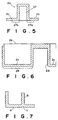
- the inlet portion of the reference hole 27 (or the reference hole 26) is not chamfered in Figure 5, the inlet portion may be tapered or rounded depending on the shape of the tip of the reference pins.
- an opening 25 through which a drive gear for rotating the reel 5 is inserted is formed in the bottom wall of the lower casing half 2b at the center thereof.
- Handling notches 29 in the form of recesses are formed respectively on the left and right side walls of the lower casing half 2b between the second locator portions 24 and the rear reference surfaces 28.
- a magnetic tape cartridge transfer means which transfers the magnetic tape cartridge 1, for instance, in a storage apparatus such as a library, grips the magnetic tape cartridge 1 at the handling notches 29.
- Screw holes 30 through screws for fastening the upper and lower casing halves 2a and 2b are inserted are provided in the bottom wall of the lower casing half 2b at four places, and an elongated hole 31 in which a projection 9a of a write-protector 9 slides is formed in the bottom wall of the lower casing half 2b at the rear end portion thereof.
- the reel 5 is provided at the center thereof with a brake mechanism for preventing the reel 5 from being rotated when the magnetic tape cartridge 1 is not being used. Further, the reel 5 is provided at the bottom surface thereof with a reel plate which is magnetically held by the drive gear and at the peripheral surface thereof with a reel gear to be brought into engagement with the drive gear. When the reel gear is engaged with the drive gear, the brake mechanism is released to permit rotation of the reel 5.
- the first and second locator portions 23 and 24 are for preliminarily locating the magnetic tape cartridge 1 with respect to a bucket (not shown) of the recording and reproducing apparatus and the magnetic tape cartridge 1 is finally located in place for recording and reproduction when the bucket is lowered to a position opposed to a magnetic head.
- the location for recording and reproduction is effected by the reference holes 26 and 27 (the front reference surfaces 26a and 27a) and the rear reference surfaces 28 on the bottom surface of the lower casing half 2b.
- the position in which the locator members abut against the abutment surfaces does not largely vary even if the position of the magnetic tape cartridge 1 relative to the recording and reproducing apparatus fluctuates in the vertical direction, whereby the position of the magnetic tape cartridge 1 as located by the locating members can be stabilized.
- portion 2c of the bottom wall of the lower casing half 2b where the front and rear reference surfaces 26a, 27a and 28 are formed is free from a rib or a step on the inner side thereof and is of a uniform thickness, no sinkmark is generated in the portion 2c of the bottom wall and accordingly the reference surfaces 26a, 27a and 28 can be flat, whereby the magnetic tape cartridge can be properly leveled and the locating accuracy is stabilized.
- a sinkmark c is generated on the surface of the bottom wall a at a portion opposed to the rib b due to difference in shrinkage when the resin is solidified.
- a sinkmark (recess) c is generated in the reference surface and the locator member of the recording and reproducing apparatus is brought into abutment against the reference surface at the sinkmark c , the magnetic tape cartridge cannot be correctly leveled with respect to the recording and reproducing apparatus, which adversely affects recording and reproduction.
- first and second locator portions 23 and 24, the reference holes 26 and 27 (the front reference surfaces 26a and 27a) and the rear reference surfaces 28 may be changed as desired without limited to those in the illustrated embodiment.
Landscapes
- Magnetic Record Carriers (AREA)
- Holding Or Fastening Of Disk On Rotational Shaft (AREA)
- Packaging Of Annular Or Rod-Shaped Articles, Wearing Apparel, Cassettes, Or The Like (AREA)
- Unwinding Webs (AREA)
Abstract
Description
Claims (4)
- A magnetic tape cartridge comprising a magnetic tape wound around a single reel and a cartridge casing in which the reel is housed for rotation, the cartridge casing being provided on a side surface thereof with a locator portion having an abutment surface which is adapted to abut against a locator member of a recording and reproducing apparatus to locate the magnetic tape cartridge in place with respect to the recording and reproducing apparatus, wherein the improvement comprises thatthe abutment surface of the locator portion is provided with a draft angle smaller than the draft angle for the other part of the side surface of the cartridge casing.
- A magnetic tape cartridge as defined in Claim 1 in which the abutment surface of the locator portion is low in surface roughness.
- A magnetic tape cartridge comprising a magnetic tape wound around a single reel and a cartridge casing in which the reel is housed for rotation, the cartridge casing being provided on its bottom surface with a reference surface which is adapted to abut against a locator member of a recording and reproducing apparatus to locate the magnetic tape cartridge in place with respect to the recording and reproducing apparatus, wherein the improvement comprises thatthe bottom wall of the cartridge casing is uniform in thickness and free from a rib or a step at the part where the reference surface is provided.
- A magnetic tape cartridge as defined in Claim 3 in which the bottom wall of the cartridge casing is small in thickness.
Priority Applications (1)
| Application Number | Priority Date | Filing Date | Title |
|---|---|---|---|
| EP03008500A EP1327987B1 (en) | 1999-11-04 | 2000-11-03 | Magnetic tape cartridge |
Applications Claiming Priority (4)
| Application Number | Priority Date | Filing Date | Title |
|---|---|---|---|
| JP31354799 | 1999-11-04 | ||
| JP31354899 | 1999-11-04 | ||
| JP31354899 | 1999-11-04 | ||
| JP31354799 | 1999-11-04 |
Related Child Applications (1)
| Application Number | Title | Priority Date | Filing Date |
|---|---|---|---|
| EP03008500A Division EP1327987B1 (en) | 1999-11-04 | 2000-11-03 | Magnetic tape cartridge |
Publications (3)
| Publication Number | Publication Date |
|---|---|
| EP1098318A2 true EP1098318A2 (en) | 2001-05-09 |
| EP1098318A3 EP1098318A3 (en) | 2002-08-28 |
| EP1098318B1 EP1098318B1 (en) | 2004-03-10 |
Family
ID=26567609
Family Applications (2)
| Application Number | Title | Priority Date | Filing Date |
|---|---|---|---|
| EP00123930A Expired - Lifetime EP1098318B1 (en) | 1999-11-04 | 2000-11-03 | Magnetic tape cartridge |
| EP03008500A Expired - Lifetime EP1327987B1 (en) | 1999-11-04 | 2000-11-03 | Magnetic tape cartridge |
Family Applications After (1)
| Application Number | Title | Priority Date | Filing Date |
|---|---|---|---|
| EP03008500A Expired - Lifetime EP1327987B1 (en) | 1999-11-04 | 2000-11-03 | Magnetic tape cartridge |
Country Status (4)
| Country | Link |
|---|---|
| US (1) | US6525907B1 (en) |
| EP (2) | EP1098318B1 (en) |
| CN (2) | CN1207713C (en) |
| DE (2) | DE60008835T2 (en) |
Families Citing this family (3)
| Publication number | Priority date | Publication date | Assignee | Title |
|---|---|---|---|---|
| US6657817B2 (en) * | 2000-09-19 | 2003-12-02 | Fuji Photo Film Co., Ltd. | Cassette housing case having an engagement recess and one or more engagement protrusions |
| JP2004086946A (en) * | 2002-08-23 | 2004-03-18 | Fuji Photo Film Co Ltd | Magnetic tape cartridge |
| JP4167033B2 (en) * | 2002-08-30 | 2008-10-15 | 富士フイルム株式会社 | Recording tape cartridge |
Family Cites Families (12)
| Publication number | Priority date | Publication date | Assignee | Title |
|---|---|---|---|---|
| US3672603A (en) * | 1970-06-26 | 1972-06-27 | Cartridge Television Inc | Tape cartridge |
| US4426047A (en) * | 1982-03-26 | 1984-01-17 | International Business Machines Corp. | Single reel tape cartridge |
| US4477851A (en) * | 1982-06-07 | 1984-10-16 | Microtek Storage Corporation | Magnetic data storage and drive apparatus |
| US4555077A (en) * | 1983-11-25 | 1985-11-26 | Electronic Processors, Inc. | Tape cartridge |
| DE9211031U1 (en) * | 1991-09-06 | 1993-01-28 | Minnesota Mining & Mfg. Co., Saint Paul, Minn. | Single reel cassette without shrink recess on the housing and housing half for such a cassette |
| DE69321805T2 (en) | 1992-09-25 | 1999-06-17 | Minnesota Mining And Mfg. Co., Saint Paul, Minn. | Magnetic tape cassette with tape guide block locking mechanism |
| US5610789A (en) * | 1995-05-09 | 1997-03-11 | Eastman Kodak Company | Tape cartridge with a gate member slidably mounted an access door |
| JP3642950B2 (en) | 1997-12-24 | 2005-04-27 | 富士写真フイルム株式会社 | Magnetic tape cartridge |
| JP3953623B2 (en) * | 1998-03-06 | 2007-08-08 | 富士フイルム株式会社 | Magnetic tape cartridge |
| USD407084S (en) * | 1998-03-11 | 1999-03-23 | Hewlett-Packard Company | Tape cartridge housing |
| JP4053135B2 (en) * | 1998-06-08 | 2008-02-27 | 富士フイルム株式会社 | Magnetic tape cartridge |
| US6345779B1 (en) * | 1999-12-31 | 2002-02-12 | Imation Corp. | Data storage cartridge having a retainer for a leader pin |
-
2000
- 2000-11-03 CN CN00133423.9A patent/CN1207713C/en not_active Expired - Lifetime
- 2000-11-03 EP EP00123930A patent/EP1098318B1/en not_active Expired - Lifetime
- 2000-11-03 EP EP03008500A patent/EP1327987B1/en not_active Expired - Lifetime
- 2000-11-03 DE DE60008835T patent/DE60008835T2/en not_active Expired - Lifetime
- 2000-11-03 DE DE60027931T patent/DE60027931T2/en not_active Expired - Lifetime
- 2000-11-03 CN CN200410063676.1A patent/CN1275257C/en not_active Expired - Fee Related
- 2000-11-03 US US09/704,616 patent/US6525907B1/en not_active Expired - Lifetime
Also Published As
| Publication number | Publication date |
|---|---|
| CN1207713C (en) | 2005-06-22 |
| CN1300071A (en) | 2001-06-20 |
| DE60027931T2 (en) | 2006-09-14 |
| DE60027931D1 (en) | 2006-06-14 |
| EP1327987B1 (en) | 2006-05-10 |
| DE60008835D1 (en) | 2004-04-15 |
| CN1574039A (en) | 2005-02-02 |
| EP1327987A1 (en) | 2003-07-16 |
| EP1098318A3 (en) | 2002-08-28 |
| US6525907B1 (en) | 2003-02-25 |
| EP1098318B1 (en) | 2004-03-10 |
| CN1275257C (en) | 2006-09-13 |
| DE60008835T2 (en) | 2004-07-29 |
Similar Documents
| Publication | Publication Date | Title |
|---|---|---|
| US7097036B2 (en) | Cassette storing case | |
| JP2004014022A (en) | Reel | |
| JP2004014023A (en) | Reel | |
| JP3576046B2 (en) | Tape cartridge lockout apparatus and method | |
| US6443304B1 (en) | Cassette container | |
| US6717771B1 (en) | Magnetic tape cartridge having projections | |
| EP1098318B1 (en) | Magnetic tape cartridge | |
| JP2003228952A (en) | Grip part structure of recording tape cartridge | |
| EP0537678B1 (en) | Container case for magnetic tape cassette | |
| EP0450976B1 (en) | Tape cassette | |
| JP2001195864A (en) | Magnetic tape cartridge | |
| US7011263B2 (en) | Recording tape cartridge | |
| US6854680B2 (en) | Recording tape cartridge | |
| US6789760B2 (en) | Recording tape cartridge | |
| JP2001006321A (en) | Case for tape cartridge and its molding die | |
| US7104487B2 (en) | Recording tape cartridge and drive device thereof | |
| JP2000011594A (en) | Magnetic tape cartridge | |
| JP4709175B2 (en) | Magnetic tape cartridge | |
| JP2001216759A (en) | Tape cartridge | |
| JPH11339437A (en) | Magnetic tape cartridge | |
| JPH09153266A (en) | Magnetic tape cassette | |
| JP2003123429A (en) | Magnetic tape cassette |
Legal Events
| Date | Code | Title | Description |
|---|---|---|---|
| PUAI | Public reference made under article 153(3) epc to a published international application that has entered the european phase |
Free format text: ORIGINAL CODE: 0009012 |
|
| AK | Designated contracting states |
Kind code of ref document: A2 Designated state(s): AT BE CH CY DE DK ES FI FR GB GR IE IT LI LU MC NL PT SE TR |
|
| AX | Request for extension of the european patent |
Free format text: AL;LT;LV;MK;RO;SI |
|
| RIC1 | Information provided on ipc code assigned before grant |
Free format text: 7G 11B 23/107 A, 7G 11B 23/113 B, 7G 11B 15/675 B |
|
| PUAL | Search report despatched |
Free format text: ORIGINAL CODE: 0009013 |
|
| AK | Designated contracting states |
Kind code of ref document: A3 Designated state(s): AT BE CH CY DE DK ES FI FR GB GR IE IT LI LU MC NL PT SE TR |
|
| AX | Request for extension of the european patent |
Free format text: AL;LT;LV;MK;RO;SI |
|
| 17P | Request for examination filed |
Effective date: 20020925 |
|
| 17Q | First examination report despatched |
Effective date: 20021129 |
|
| REG | Reference to a national code |
Ref country code: GB Ref legal event code: FG4D |
|
| AKX | Designation fees paid |
Designated state(s): DE FR GB |
|
| GRAP | Despatch of communication of intention to grant a patent |
Free format text: ORIGINAL CODE: EPIDOSNIGR1 |
|
| GRAS | Grant fee paid |
Free format text: ORIGINAL CODE: EPIDOSNIGR3 |
|
| GRAA | (expected) grant |
Free format text: ORIGINAL CODE: 0009210 |
|
| AK | Designated contracting states |
Kind code of ref document: B1 Designated state(s): DE FR GB |
|
| RIN1 | Information on inventor provided before grant (corrected) |
Inventor name: SHIGA, HIDEAKI Inventor name: MORITA, KIYOO Inventor name: ISHIHARA, YUSUKE Inventor name: TAKAHASHI, DAISUKE |
|
| RIN2 | Information on inventor provided after grant (corrected) |
Inventor name: ISHIHARA, YUSUKE Inventor name: TAKAHASHI, DAISUKE Inventor name: MORITA, KIYOO Inventor name: SHIGA, HIDEAKI |
|
| REG | Reference to a national code |
Ref country code: IE Ref legal event code: FG4D |
|
| REF | Corresponds to: |
Ref document number: 60008835 Country of ref document: DE Date of ref document: 20040415 Kind code of ref document: P |
|
| ET | Fr: translation filed | ||
| PLBE | No opposition filed within time limit |
Free format text: ORIGINAL CODE: 0009261 |
|
| STAA | Information on the status of an ep patent application or granted ep patent |
Free format text: STATUS: NO OPPOSITION FILED WITHIN TIME LIMIT |
|
| 26N | No opposition filed |
Effective date: 20041213 |
|
| REG | Reference to a national code |
Ref country code: GB Ref legal event code: 732E |
|
| REG | Reference to a national code |
Ref country code: FR Ref legal event code: CD Ref country code: FR Ref legal event code: TP |
|
| REG | Reference to a national code |
Ref country code: FR Ref legal event code: PLFP Year of fee payment: 16 |
|
| REG | Reference to a national code |
Ref country code: FR Ref legal event code: PLFP Year of fee payment: 17 |
|
| REG | Reference to a national code |
Ref country code: FR Ref legal event code: PLFP Year of fee payment: 18 |
|
| REG | Reference to a national code |
Ref country code: FR Ref legal event code: PLFP Year of fee payment: 19 |
|
| PGFP | Annual fee paid to national office [announced via postgrant information from national office to epo] |
Ref country code: DE Payment date: 20191022 Year of fee payment: 20 |
|
| PGFP | Annual fee paid to national office [announced via postgrant information from national office to epo] |
Ref country code: FR Payment date: 20191015 Year of fee payment: 20 |
|
| PGFP | Annual fee paid to national office [announced via postgrant information from national office to epo] |
Ref country code: GB Payment date: 20191031 Year of fee payment: 20 |
|
| REG | Reference to a national code |
Ref country code: DE Ref legal event code: R071 Ref document number: 60008835 Country of ref document: DE |
|
| REG | Reference to a national code |
Ref country code: GB Ref legal event code: PE20 Expiry date: 20201102 |
|
| PG25 | Lapsed in a contracting state [announced via postgrant information from national office to epo] |
Ref country code: GB Free format text: LAPSE BECAUSE OF EXPIRATION OF PROTECTION Effective date: 20201102 |