EP1098307A2 - Threading mechanism for magnetic recording/reproducing apparatus - Google Patents
Threading mechanism for magnetic recording/reproducing apparatus Download PDFInfo
- Publication number
- EP1098307A2 EP1098307A2 EP00309760A EP00309760A EP1098307A2 EP 1098307 A2 EP1098307 A2 EP 1098307A2 EP 00309760 A EP00309760 A EP 00309760A EP 00309760 A EP00309760 A EP 00309760A EP 1098307 A2 EP1098307 A2 EP 1098307A2
- Authority
- EP
- European Patent Office
- Prior art keywords
- cartridge
- leader
- loader
- pin
- leader pin
- Prior art date
- Legal status (The legal status is an assumption and is not a legal conclusion. Google has not performed a legal analysis and makes no representation as to the accuracy of the status listed.)
- Granted
Links
- 238000010276 construction Methods 0.000 description 8
- 230000002093 peripheral effect Effects 0.000 description 6
- 230000004048 modification Effects 0.000 description 1
- 238000012986 modification Methods 0.000 description 1
Images





Classifications
-
- G—PHYSICS
- G11—INFORMATION STORAGE
- G11B—INFORMATION STORAGE BASED ON RELATIVE MOVEMENT BETWEEN RECORD CARRIER AND TRANSDUCER
- G11B15/00—Driving, starting or stopping record carriers of filamentary or web form; Driving both such record carriers and heads; Guiding such record carriers or containers therefor; Control thereof; Control of operating function
- G11B15/60—Guiding record carrier
- G11B15/66—Threading; Loading; Automatic self-loading
- G11B15/67—Threading; Loading; Automatic self-loading by extracting end of record carrier from container or spool
Definitions
- the present invention relates to a threading mechanism for a magnetic recording/reproducing apparatus.
- a particular apparatus to be described by way of example in illustration of the invention is for taking out a leader pin secured to one end of a magnetic recording tape from a single reel cartridge, moving the leader pin to a predetermined guide path and threading the magnetic recording tape around a reel in the apparatus.
- the threading drive is designed so that a leader block 16 having a hook 16-2 which is hooked to the leader pin to hold the leader pin (not shown) is guided to a guide path (not shown) by a threading pin 10.
- the hook 16-2 is hooked to the leader pin through the operation of guides (guide grooves 15-1, 15-2) of a guide cam 15 and a retractor block 17 which are respectively secured to the deck base (not shown).
- the leader block 16 has pins 16-3 and 16-4 at the upper and lower portions thereof, and they are located in the guide grooves 15-1,15-2 and the groove 17-1 of the retractor block 17 respectively.
- a retractor cam 4-8 provided to the cartridge loader (not shown)
- the retractor block 17 is rotated around the pin 2-2 serving as the support shaft thereof against the tensile force of a retractor spring 13-3 and the-threading pin 10 is also moved to the guide path side, whereby the pins 16-3, 16-4 are slid in the guide groove 15-2 and the groove 17-1.
- the leader block 16 is rotated while being guided along the groove 15-2 and hooked to the leader pin.
- the pins 16-3, 16-4 are released from the guide grooves 15-1 and 17-1 by the time at which the loading operation is completed, and the leader block 16 is moved to the guide path while being guided by the threading pin 10.
- the leader block 16 is rotated by both the rotation of the retractor block 17 and the pulling operation of the threading pin 10 to the guide path side, whereby the leader pin is hooked by the hook and clamped by the leader block 16. Therefore, a stable operation cannot be achieved unless there is a synchronizing adjustment between the retractor block 17 and the threading pin 10 which is accurately carried out.
- a threading mechanism for a magnetic recording/reproducing apparatus will be described below, by way of example in illustration of the invention, in which a clamping operation of a leader pin by a leader block is carried out by a simple rotational motion of the retractor block, thereby achieving a more stable operation.
- One particular threading mechanism to be described below is for taking out a leader pin secured to one end of a magnetic recording tape from a single reel cartridge, in which the leader pin is moved to a predetermined guide path and the magnetic recording tape is threaded around a reel in a magnetic recording/reproducing apparatus, the apparatus including a cartridge loader for holding a cartridge, a deck base upon which a loader guide is mounted for moving the cartridge loader to a cartridge loading position, and a threader drive for holding the leader pin and guiding the leader pin to the reel through the predetermined guide path when the cartridge loader is moved to the cartridge loading position, wherein the threader drive includes a leader block having a hook which holds the leader pin, the leader block is rotated to engage the hook with the leader pin in cooperation with a retractor cam provided to the cartridge loader and a retractor is provided to the deck base.
- a magnetic recording/reproducing apparatus is applied to a recording medium having magnetic tape 1-1 in single reel cartridge 1.
- the magnetic tape 1-1 has a leader pin 1-2 at the leading end thereof, and the upper and lower ends of the leader pin 1-2 are fitted into pin fixing grooves 1-3 formed at the upper and lower edges inside a tape inlet/outlet port of the cartridge 1, so as to be supported in the direction indicated -by an arrow A in Figs. 3A and 3B.
- a loader guide 3 which is moulded from a panel, is mounted on the upper surface of a deck base 2, and there are bearing guide slits (or rails) 3-1 to 3-5 on both the side surfaces and upper surface of the loader guide 3. Further, there is a pin 3-6 on the upper surface of the loader guide 3.
- a cartridge loader 4 which is guided in the loading direction on the deck base 2 along the loader guide 3 has bearings 4-1 to 4-4 at both of the side surfaces thereof, and bearings 4-5, 4-6 at the upper surface thereof. These bearings are movable along bearing guide slits (or rails) 3-1 to 3-4 (the guide slits corresponding to the bearings 4-3, 4-4 are not shown). Further, the cartridge loader 4 also has a loader drive roller 4-7 at the upper surface thereof. The loader drive roller 4-7 is so arranged that it penetrates through a slit 3-5 in the upper surface of the loader guide 3 and projects upwardly therefrom. The cartridge loader 4 has a retractor cam 4-8 at the lower portion thereof.
- cam plate 5 is secured to the upper surface of the deck base 2 so as to confront the cartridge loading position.
- a threader guide groove 5-1 serving as a guide path for guiding a threader drive (described later) is formed on the lower surface of the cam plate 5, and there is a pivot shaft 5-2 on the upper surface of the cam plate 5.
- a threader drive gear 7 is freely rotatably supported by the pivot shaft 5-2.
- a loader drive gear 6, which is engaged with the threader drive gear 7, is freely rotatably supported on a pivot shaft 3-6 which is on the upper surface of the loader guide plate 3, and there is a loader drive cam groove, having a radial portion 6-1 and a peripheral portion 6-2, on the rear surface of the loader guide plate 3.
- the loader drive roller 4-7 is fitted in the loader drive cam groove so as to be guided along the loader drive cam groove.
- the threader drive gear 7 has a threader drive cam groove with a radial portion 7-1 and a peripheral portion 7-2 on the back surface thereof, and a threader drive roller 8-1 is fitted in the threader drive cam groove so as to be guided along the threader drive cam groove.
- a threader drive roller 8-1 on the upper surface of a threader drive arm 8, which is freely rotatably supported through the pivot shaft 2-1 to the deck base 2 side (in this apparatus, the upper surface of the cam plate 5), and it swings the threader drive arm 8 around the pivot shaft 2-1 through the threader drive cam groove as a result of the rotational motion of the threader drive gear 7.
- a threading arm 9 is freely movably mounted to the tip of the threader drive arm 8 through a pin 8-2, and a threading pin 10 is supported at the tip of the threading arm 9.
- a threading roller 10-1 is secured to the upper end of the threading pin 10 (the detailed construction is shown in Figs. 19 and 20).
- the threading roller 10-1 is fitted in the threader guide groove 5-1 so as to be guided along the threader guide groove 5-1, and it makes a sliding motion along the threader guide groove 5-1 interlockingly with the motion of the threading arm 9.
- the threading mechanism supports a threading block 11 at the lower portion of the threading pin 10, so that the threading block 11 is freely rotatable.
- a leader block 12 is freely rotatably supported at the side portion of the threading block 11 through a pin 12-1 (eccentric to the threading pin 10) (see Figs. 19 and 20).
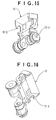
- the leader block 12 has at the tip thereof a hook 12-2, which is hooked to the leader pin 1-2 to clamp (grasp) the leader pin 1-2, and there is a fitting groove 12-3 at the lower end portion of the hook 12-2 (see Fig. 15).
- the retractor at the deck base side has, at the top portion of the retractor table (block) 13, a projection 13-1 which is detachably fitted to the fitting groove 12-3 (see X portion of Fig. 20), and the retractor table 13 is freely rotatably supported by the pivot shaft 2-2 provided to the deck base 2 (at the fitting position at which the projection 13-1 being fitted in the fitting groove 12-3, the pivot shaft 2-2 being coaxial with the pin 12-1).
- retractor pin 13-2 is secured to the retractor table 13, and the retractor table 13 is pulled in a direction F (see Fig. 9A) by a retractor spring 13-3 fitted to the retractor pin 13-2.
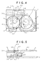
- Fig. 7 the state of the threading mechanism is shown before the cartridge 1 is inserted into the cartridge loader 4 and fed to the cartridge loading position of the deck base 2, that is, the state of the threading mechanism is shown before the start of the loading operation.
- the loader drive roller 4-7 is located at the radial portion 6-1 of the loader drive cam groove
- the threading drive roller 8-1 is located at the peripheral portion 7-2 of the threader drive cam groove.
- the leader block 12 is engaged with the retractor table 13 such that the projection 13-1 is fitted in the fitting groove 12-3, and pulled in the direction F by the retractor spring 13-3 (see Fig. 9A).
- the driving force needed (a driving source is not shown) is applied to the loader drive gear 6 to rotate the loader drive gear 6 in the direction indicated by an arrow B, whereby the loader drive roller 4-7 starts its sliding motion at the position of the radial portion 6- 1 of the loader drive groove.
- the bearings 4-1 to 4-6 are caused to slide along the bearing slits (or rails) 3-1 to 3-4 of the loader guide 3, and the cartridge loader 4 makes a straight motion in the direction indicated by an arrow D to load the cartridge 1 to the loading position (see Fig. 10).
- the threader drive gear 7 is rotated in the direction indicated by an arrow C by the rotation of the loader drive gear 6 (see Fig. 10).
- the threader drive roller 8-1 is located at the peripheral portion 7-2 of the threader drive cam groove, and thus the location thereof is not varied by the rotation of the threader drive gear 7. Accordingly, the threader drive arm 8 is kept stationary and the threading operation does not occur in the conditions shown in of Figs. 7 and 10.
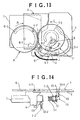
- the cartridge loader 4 further makes a sliding motion in the direction indicated by the arrow D by the further rotation of the loader drive gear 6 in the direction indicated by the arrow B, and at this time the retractor pin 13-2 is pushed in the direction indicated by the arrow D by the retractor cam 4-8 extending downwardly at the lower portion of the cartridge loader 4. Therefore, the retractor table 13 is rotated around the pivot shaft 2-2 in the direction indicated by an arrow E (see Figs. 9A to 9C).
- the leader block 12 is also rotated by the rotation of the retractor table 13. At this time, the leader block 12 is guided to the tape inlet/outlet port of the cartridge 1, and the hook 12-2 is hooked to the leader pin 1-2 from the rear side of the loading direction, whereby the leader pin 1- 2 is clamped (grasped).
- the loader drive roller 4-7 completes its lane change from the radial portion 6-1 of the loader drive cam groove to the peripheral portion 6-2 thereof. Therefore, the loader drive roller 4-7 makes no further motion, even when the loader drive gear 6 further rotates, and thus is kept stationary at the current position.
- the threader drive roller 8-1 completes its lane change from the peripheral portion 7-2 of the threader drive cam groove to the radial portion 7-1 thereof, and it is moved by the rotation of the threader drive gear 7 so as to interchange with the loader drive roller 4-7, whereby the threader drive arm 8 is rotated from the condition shown in Fig. 10.
- the threader drive roller 8-1 which has completed its lane change to the radial portion 7-1 of the threader drive cam groove, experiences a driving force from the threader drive gear 7 as a result of the rotation of the threader drive gear 7 in the direction indicated by the arrow C, and by further rotating the threader drive arm 8, the threading arm 9 operates so as to guide the threading roller 10-1 in the threader guide groove 5-1.
- the threader drive roller 8-1 is moved while travelling via a locus H, and the threader drive arm 8 is rotated around the pivot shaft 2-1.
- the leader block 12 is pulled in the direction indicated by an arrow J through the threading pin 10 and the threading block 11 (see Fig. 13), and the magnetic tape 1-1 is drawn out and guided to a reel (not shown) at the side of the apparatus, while the leader pin 1-2 is clamped by the hook 12-2.
- the leader pin 1-2 is subjected to the threading operation as described above.
- the direction of the force acting on the leader block 12 at this time is parallel to the fitting direction between the groove 12-3 and the projection 13-1, so that the leader block 12 is released from the restraint of the retractor table 13 and is thus allowed to move in the direction indicated by the arrow J as described above.
- this operation can be performed by inversely rotating the loader drive gear 6, that is, by inversely tracing a series of operations, as described above.
- a reel motor (not shown) for rewinding the magnetic tape 1-1 itself may be provided to the deck base 2 so as to face the lower portion of the cartridge 1.
- plate springs 14 are added to the leader block 12 in the threading mechanism to enhance the certainty of the clamp (grasp) of the leader pin 1-2. That is, as shown in Figs. 21 and 22, the plate springs 14 (that is the elastically holding means) are secured so that they surround the leader block 12. In this second apparatus the plate springs 14 press the leader pin 1-2 at the fitting position of the leader pin 1-2 to enhance the holding power of the leader block 12 to the leader pin 1-2. Accordingly, the leader pin 1-2 can be restrained from falling off the leader block 12, due to an unintentional operation.
- the threader drive which holds the leader pin and guides it to the reel through the guide path, rotates the leader block thereof, in cooperation of the retractor cam provided to the cartridge loader and the retractor provided to the deck base, to fit the hook of the leader block to the leader pin from the rear side thereof along the loading direction of the cartridge loader, thereby clamping the leader pin with the leader block, and then guides the leader pin to the guide path.
Landscapes
- Replacement Of Web Rolls (AREA)
- Photographic Developing Apparatuses (AREA)
- Packaging Of Annular Or Rod-Shaped Articles, Wearing Apparel, Cassettes, Or The Like (AREA)
Abstract
Description
Claims (4)
- A threading mechanism for taking out a leader pin secured to one end of a magnetic recording tape from a single reel cartridge, moving the leader pin to a predetermined guide path and threading the magnetic recording tape around a reel in a magnetic recording/reproducing apparatus, the mechanism including a cartridge loader for holding the cartridge, a deck base on which a loader guide is mounted for moving the cartridge loader to a cartridge loading position, and a threader drive for holding the leader pin and guiding the leader pin to the reel through the predetermined guide path when the cartridge loader is moved to the cartridge loading position, wherein the threader drive has a leader block having the a hook which holds the leader pin, and wherein the leader block is rotated to engage the hook with the leader pin in cooperation with a retractor cam provided to the cartridge loader and a retractor provided to the deck base.
- A threading mechanism as claimed in claim 1, wherein the hook is engaged with the leader pin from the rear side of the leader pin along the loading direction of the cartridge loader.
- A threading mechanism as claimed in claim 1, wherein, during the movement of the cartridge loader to the cartridge loading position, the retractor is rotated around the retractor pin by the retractor cam, and the leader block is rotated to engage the hook with the leader pin, and wherein the retractor is detachably mounted to the leader block so that the leader block is released therefrom at the time at which the cartridge loader reaches the cartridge loading position.
- A threading mechanism as claimed in claim 1, wherein the leader block has elastically holding means for elastically holding the leader pin when the leader pin is clamped by the leader block.
Applications Claiming Priority (2)
| Application Number | Priority Date | Filing Date | Title |
|---|---|---|---|
| JP31563399A JP3390385B2 (en) | 1999-11-05 | 1999-11-05 | Threading mechanism in magnetic recording / reproducing device |
| JP31563399 | 1999-11-05 |
Publications (3)
| Publication Number | Publication Date |
|---|---|
| EP1098307A2 true EP1098307A2 (en) | 2001-05-09 |
| EP1098307A3 EP1098307A3 (en) | 2001-07-18 |
| EP1098307B1 EP1098307B1 (en) | 2005-11-30 |
Family
ID=18067719
Family Applications (1)
| Application Number | Title | Priority Date | Filing Date |
|---|---|---|---|
| EP00309760A Expired - Lifetime EP1098307B1 (en) | 1999-11-05 | 2000-11-03 | Threading mechanism for magnetic recording/reproducing apparatus |
Country Status (3)
| Country | Link |
|---|---|
| US (1) | US6471150B1 (en) |
| EP (1) | EP1098307B1 (en) |
| JP (1) | JP3390385B2 (en) |
Cited By (5)
| Publication number | Priority date | Publication date | Assignee | Title |
|---|---|---|---|---|
| EP1265237A3 (en) * | 2001-06-05 | 2006-05-03 | NEC Corporation | Cartridge magnetic tape device having magnetic head cleaning mechanism |
| EP1313102A3 (en) * | 2001-10-19 | 2006-05-24 | NEC Corporation | Tape cartridge with tape having a leader pin |
| US7420767B2 (en) * | 2004-11-30 | 2008-09-02 | Mitsumi Electric Co., Ltd. | Recording and/or reproducing device having a positioning arrangement for fixing a grabber in place |
| US7540442B2 (en) | 2004-06-17 | 2009-06-02 | Nec Corporation | Apparatus for threading a tape from a cartridge |
| EP1843339A3 (en) * | 2006-04-05 | 2009-09-16 | Mitsumi Electric Co., Ltd. | Recording and/or reproducing device wherein shaft is out of contact with pull-out assembly on rotating take-up reel |
Families Citing this family (14)
| Publication number | Priority date | Publication date | Assignee | Title |
|---|---|---|---|---|
| KR100848122B1 (en) * | 2000-11-02 | 2008-07-24 | 소니 가부시끼 가이샤 | 1 reel tape cartridge and recording / playback apparatus using the same |
| US6889927B2 (en) * | 2002-07-03 | 2005-05-10 | Segway Systems, Llc | Tape threading apparatus having take-up hub with gap filling block for data storage systems and method therefor |
| JP3826880B2 (en) | 2002-11-21 | 2006-09-27 | 日本電気株式会社 | Threading mechanism in magnetic recording / reproducing apparatus |
| JP3783683B2 (en) | 2003-01-16 | 2006-06-07 | 日本電気株式会社 | Leader block rotation mechanism of cartridge magnetic tape device |
| US6908055B2 (en) * | 2003-02-27 | 2005-06-21 | Tandberg Data Asa | System for extracting magnetic recording tape from a tape cartridge for engagement with a take-up reel |
| US6921038B2 (en) | 2003-08-15 | 2005-07-26 | International Business Machines Corporation | Apparatus and method to releaseably attach a tape leader pin |
| US7100863B2 (en) * | 2003-12-16 | 2006-09-05 | Lincoln Global, Inc. | Floating liner |
| US7334750B2 (en) * | 2004-05-13 | 2008-02-26 | Storage Technology Corporation | Tape drive with leader connecting mechanism |
| US7239474B1 (en) | 2004-05-13 | 2007-07-03 | Storage Technology Corporation | Leader connecting mechanism |
| US7224549B1 (en) | 2004-05-17 | 2007-05-29 | Storage Technology Corporation | Apparatus for positioning a data storage device |
| JP2006179052A (en) * | 2004-12-21 | 2006-07-06 | Mitsumi Electric Co Ltd | Recording / playback device |
| JP4593355B2 (en) * | 2005-05-12 | 2010-12-08 | Necパーソナルプロダクツ株式会社 | Magnetic tape unit |
| JP4328740B2 (en) | 2005-05-12 | 2009-09-09 | Necパーソナルプロダクツ株式会社 | Leader block rotation mechanism, tape cartridge drive device |
| US7661619B2 (en) * | 2006-05-17 | 2010-02-16 | Quantum Corporation | Buckler for tape drives |
Family Cites Families (17)
| Publication number | Priority date | Publication date | Assignee | Title |
|---|---|---|---|---|
| US4477851A (en) | 1982-06-07 | 1984-10-16 | Microtek Storage Corporation | Magnetic data storage and drive apparatus |
| EP0143598A3 (en) | 1983-11-25 | 1986-09-03 | Electronic Processors, Inc. | Magnetic tape recording and reproducing system with automatic tape threading |
| US4991037A (en) | 1986-03-26 | 1991-02-05 | Copal Co., Ltd. | Apparatus for manipulating a magnetic tape cartridge and the magnetic tape contained therewithin |
| JPS63108551A (en) * | 1986-10-27 | 1988-05-13 | Nakamichi Corp | Leader block pulling-out device |
| US5155639A (en) * | 1988-11-03 | 1992-10-13 | U.S. Philips Corporation | Transport apparatus for a single reel tape cartridge |
| JPH0268344U (en) * | 1988-11-10 | 1990-05-23 | ||
| JPH06267160A (en) | 1993-03-15 | 1994-09-22 | Hitachi Ltd | Magnetic tape unit |
| US5542260A (en) * | 1994-08-31 | 1996-08-06 | Bourne; Richard C. | Night-storage underfloor cooling systems |
| JPH08195003A (en) | 1995-01-20 | 1996-07-30 | Hitachi Ltd | Magnetic tape device and magnetic tape threading method |
| EP0925583B1 (en) | 1997-04-03 | 2003-06-18 | Koninklijke Philips Electronics N.V. | Recording and/or reproducing system including a magnetic-tape cassette comprising a coupling element |
| US6034839A (en) * | 1997-11-07 | 2000-03-07 | Seagate Technology, Inc. | Mechanism and method for loading a tape from a cartridge to a take-up reel |
| US6050514A (en) | 1998-01-21 | 2000-04-18 | Hewlett-Packard Company | Tape block and take-up reel assembly for a magnetic tape transport system |
| US5927633A (en) | 1998-07-22 | 1999-07-27 | Hewlett-Packard Company | Resiliently biased parking seat for receiving the leader pin of a single reel tape cartridge |
| US5979813A (en) | 1998-09-30 | 1999-11-09 | Hewlett-Packard Company | Tape threading apparatus |
| JP2002530790A (en) | 1998-11-12 | 2002-09-17 | コーニンクレッカ フィリップス エレクトロニクス エヌ ヴィ | Recording and / or reproducing apparatus having driving means for operating a holder means for a cassette and holding means for a tape pull-out element |
| US6318656B1 (en) | 1998-11-12 | 2001-11-20 | U.S. Philips Corporation | Recording and/or reproducing device having a tape pull-out element and having latching means for this tape pull-out element |
| JP3390361B2 (en) | 1999-05-18 | 2003-03-24 | 米沢日本電気株式会社 | Loading / threading mechanism of cartridge magnetic tape unit |
-
1999
- 1999-11-05 JP JP31563399A patent/JP3390385B2/en not_active Expired - Fee Related
-
2000
- 2000-11-02 US US09/704,981 patent/US6471150B1/en not_active Expired - Lifetime
- 2000-11-03 EP EP00309760A patent/EP1098307B1/en not_active Expired - Lifetime
Cited By (5)
| Publication number | Priority date | Publication date | Assignee | Title |
|---|---|---|---|---|
| EP1265237A3 (en) * | 2001-06-05 | 2006-05-03 | NEC Corporation | Cartridge magnetic tape device having magnetic head cleaning mechanism |
| EP1313102A3 (en) * | 2001-10-19 | 2006-05-24 | NEC Corporation | Tape cartridge with tape having a leader pin |
| US7540442B2 (en) | 2004-06-17 | 2009-06-02 | Nec Corporation | Apparatus for threading a tape from a cartridge |
| US7420767B2 (en) * | 2004-11-30 | 2008-09-02 | Mitsumi Electric Co., Ltd. | Recording and/or reproducing device having a positioning arrangement for fixing a grabber in place |
| EP1843339A3 (en) * | 2006-04-05 | 2009-09-16 | Mitsumi Electric Co., Ltd. | Recording and/or reproducing device wherein shaft is out of contact with pull-out assembly on rotating take-up reel |
Also Published As
| Publication number | Publication date |
|---|---|
| JP2001135003A (en) | 2001-05-18 |
| EP1098307B1 (en) | 2005-11-30 |
| US6471150B1 (en) | 2002-10-29 |
| JP3390385B2 (en) | 2003-03-24 |
| EP1098307A3 (en) | 2001-07-18 |
Similar Documents
| Publication | Publication Date | Title |
|---|---|---|
| EP1098307A2 (en) | Threading mechanism for magnetic recording/reproducing apparatus | |
| KR880000325B1 (en) | Tape loading apparatus | |
| SU1521295A3 (en) | Device for fitting information carrier in tape recorder | |
| CA1232208A (en) | Disc players fitted for automatic change of discs | |
| KR880014540A (en) | Magnetic recording and playback equipment | |
| EP0283131B1 (en) | Paper tape control unit | |
| US4819891A (en) | Mode changing mechanism in tape recorder | |
| US3943569A (en) | Cassette tape transport with adjustable head | |
| US5006941A (en) | Reversible drive mechanism for a tape recording apparatus | |
| US3692257A (en) | Automatic tape recording-reproducing apparatus | |
| JP2578625B2 (en) | Cassette mounting device | |
| KR0147576B1 (en) | Cassette loading device | |
| JP2986318B2 (en) | Magnetic recording / reproducing device | |
| US3603527A (en) | Mounting apparatus for web-handling machine | |
| JPH01192050A (en) | Magnetic recording and reproducing device | |
| US3734427A (en) | Adjustable spindle arm for motion picture projectors | |
| JPH0470707B2 (en) | ||
| EP0045328A1 (en) | A loading mechanism for a cassette tape recorder | |
| KR100224990B1 (en) | Disk drive of compact disk | |
| JPH04357354A (en) | Cam mechanism | |
| JPS626456A (en) | Loading device for cassette | |
| JPS6323781Y2 (en) | ||
| JPS6235160Y2 (en) | ||
| JPH036588B2 (en) | ||
| JPS6364819B2 (en) |
Legal Events
| Date | Code | Title | Description |
|---|---|---|---|
| PUAI | Public reference made under article 153(3) epc to a published international application that has entered the european phase |
Free format text: ORIGINAL CODE: 0009012 |
|
| AK | Designated contracting states |
Kind code of ref document: A2 Designated state(s): FR GB |
|
| AX | Request for extension of the european patent |
Free format text: AL;LT;LV;MK;RO;SI |
|
| PUAL | Search report despatched |
Free format text: ORIGINAL CODE: 0009013 |
|
| AK | Designated contracting states |
Kind code of ref document: A3 Designated state(s): AT BE CH CY DE DK ES FI FR GB GR IE IT LI LU MC NL PT SE TR |
|
| AX | Request for extension of the european patent |
Free format text: AL;LT;LV;MK;RO;SI |
|
| 17P | Request for examination filed |
Effective date: 20010619 |
|
| AKX | Designation fees paid |
Free format text: FR GB |
|
| REG | Reference to a national code |
Ref country code: DE Ref legal event code: 8566 |
|
| 17Q | First examination report despatched |
Effective date: 20030918 |
|
| GRAP | Despatch of communication of intention to grant a patent |
Free format text: ORIGINAL CODE: EPIDOSNIGR1 |
|
| GRAS | Grant fee paid |
Free format text: ORIGINAL CODE: EPIDOSNIGR3 |
|
| GRAA | (expected) grant |
Free format text: ORIGINAL CODE: 0009210 |
|
| AK | Designated contracting states |
Kind code of ref document: B1 Designated state(s): FR GB |
|
| REG | Reference to a national code |
Ref country code: GB Ref legal event code: FG4D |
|
| ET | Fr: translation filed | ||
| PLBE | No opposition filed within time limit |
Free format text: ORIGINAL CODE: 0009261 |
|
| STAA | Information on the status of an ep patent application or granted ep patent |
Free format text: STATUS: NO OPPOSITION FILED WITHIN TIME LIMIT |
|
| 26N | No opposition filed |
Effective date: 20060831 |
|
| PGFP | Annual fee paid to national office [announced via postgrant information from national office to epo] |
Ref country code: GB Payment date: 20141029 Year of fee payment: 15 Ref country code: FR Payment date: 20141110 Year of fee payment: 15 |
|
| GBPC | Gb: european patent ceased through non-payment of renewal fee |
Effective date: 20151103 |
|
| REG | Reference to a national code |
Ref country code: FR Ref legal event code: ST Effective date: 20160729 |
|
| PG25 | Lapsed in a contracting state [announced via postgrant information from national office to epo] |
Ref country code: GB Free format text: LAPSE BECAUSE OF NON-PAYMENT OF DUE FEES Effective date: 20151103 |
|
| PG25 | Lapsed in a contracting state [announced via postgrant information from national office to epo] |
Ref country code: FR Free format text: LAPSE BECAUSE OF NON-PAYMENT OF DUE FEES Effective date: 20151130 |