EP1098092A2 - Stator blade - Google Patents
Stator blade Download PDFInfo
- Publication number
- EP1098092A2 EP1098092A2 EP00307193A EP00307193A EP1098092A2 EP 1098092 A2 EP1098092 A2 EP 1098092A2 EP 00307193 A EP00307193 A EP 00307193A EP 00307193 A EP00307193 A EP 00307193A EP 1098092 A2 EP1098092 A2 EP 1098092A2
- Authority
- EP
- European Patent Office
- Prior art keywords
- vane
- root
- tip
- trailing edge
- waist
- Prior art date
- Legal status (The legal status is an assumption and is not a legal conclusion. Google has not performed a legal analysis and makes no representation as to the accuracy of the status listed.)
- Granted
Links
- 238000009792 diffusion process Methods 0.000 claims description 10
- 230000001965 increasing effect Effects 0.000 description 9
- 238000000926 separation method Methods 0.000 description 8
- 230000007423 decrease Effects 0.000 description 4
- 238000009826 distribution Methods 0.000 description 4
- 239000007789 gas Substances 0.000 description 4
- 230000000295 complement effect Effects 0.000 description 3
- 230000006835 compression Effects 0.000 description 3
- 238000007906 compression Methods 0.000 description 3
- 238000011144 upstream manufacturing Methods 0.000 description 3
- 241000237509 Patinopecten sp. Species 0.000 description 2
- 239000000567 combustion gas Substances 0.000 description 2
- 230000000694 effects Effects 0.000 description 2
- 230000008030 elimination Effects 0.000 description 2
- 238000003379 elimination reaction Methods 0.000 description 2
- 230000002708 enhancing effect Effects 0.000 description 2
- 238000004519 manufacturing process Methods 0.000 description 2
- 235000020637 scallop Nutrition 0.000 description 2
- 230000001154 acute effect Effects 0.000 description 1
- 230000002411 adverse Effects 0.000 description 1
- 238000013459 approach Methods 0.000 description 1
- 238000005219 brazing Methods 0.000 description 1
- 230000005465 channeling Effects 0.000 description 1
- 238000002485 combustion reaction Methods 0.000 description 1
- 230000003247 decreasing effect Effects 0.000 description 1
- 238000000605 extraction Methods 0.000 description 1
- 239000000446 fuel Substances 0.000 description 1
- 238000004904 shortening Methods 0.000 description 1
- 239000011885 synergistic combination Substances 0.000 description 1
- 238000003466 welding Methods 0.000 description 1
Images


Classifications
-
- F—MECHANICAL ENGINEERING; LIGHTING; HEATING; WEAPONS; BLASTING
- F01—MACHINES OR ENGINES IN GENERAL; ENGINE PLANTS IN GENERAL; STEAM ENGINES
- F01D—NON-POSITIVE DISPLACEMENT MACHINES OR ENGINES, e.g. STEAM TURBINES
- F01D5/00—Blades; Blade-carrying members; Heating, heat-insulating, cooling or antivibration means on the blades or the members
- F01D5/005—Repairing methods or devices
-
- F—MECHANICAL ENGINEERING; LIGHTING; HEATING; WEAPONS; BLASTING
- F01—MACHINES OR ENGINES IN GENERAL; ENGINE PLANTS IN GENERAL; STEAM ENGINES
- F01D—NON-POSITIVE DISPLACEMENT MACHINES OR ENGINES, e.g. STEAM TURBINES
- F01D5/00—Blades; Blade-carrying members; Heating, heat-insulating, cooling or antivibration means on the blades or the members
- F01D5/12—Blades
- F01D5/14—Form or construction
- F01D5/141—Shape, i.e. outer, aerodynamic form
-
- F—MECHANICAL ENGINEERING; LIGHTING; HEATING; WEAPONS; BLASTING
- F01—MACHINES OR ENGINES IN GENERAL; ENGINE PLANTS IN GENERAL; STEAM ENGINES
- F01D—NON-POSITIVE DISPLACEMENT MACHINES OR ENGINES, e.g. STEAM TURBINES
- F01D5/00—Blades; Blade-carrying members; Heating, heat-insulating, cooling or antivibration means on the blades or the members
- F01D5/12—Blades
- F01D5/28—Selecting particular materials; Particular measures relating thereto; Measures against erosion or corrosion
-
- F—MECHANICAL ENGINEERING; LIGHTING; HEATING; WEAPONS; BLASTING
- F01—MACHINES OR ENGINES IN GENERAL; ENGINE PLANTS IN GENERAL; STEAM ENGINES
- F01D—NON-POSITIVE DISPLACEMENT MACHINES OR ENGINES, e.g. STEAM TURBINES
- F01D5/00—Blades; Blade-carrying members; Heating, heat-insulating, cooling or antivibration means on the blades or the members
- F01D5/12—Blades
- F01D5/28—Selecting particular materials; Particular measures relating thereto; Measures against erosion or corrosion
- F01D5/282—Selecting composite materials, e.g. blades with reinforcing filaments
-
- F—MECHANICAL ENGINEERING; LIGHTING; HEATING; WEAPONS; BLASTING
- F01—MACHINES OR ENGINES IN GENERAL; ENGINE PLANTS IN GENERAL; STEAM ENGINES
- F01D—NON-POSITIVE DISPLACEMENT MACHINES OR ENGINES, e.g. STEAM TURBINES
- F01D5/00—Blades; Blade-carrying members; Heating, heat-insulating, cooling or antivibration means on the blades or the members
- F01D5/12—Blades
- F01D5/28—Selecting particular materials; Particular measures relating thereto; Measures against erosion or corrosion
- F01D5/284—Selection of ceramic materials
-
- F—MECHANICAL ENGINEERING; LIGHTING; HEATING; WEAPONS; BLASTING
- F04—POSITIVE - DISPLACEMENT MACHINES FOR LIQUIDS; PUMPS FOR LIQUIDS OR ELASTIC FLUIDS
- F04D—NON-POSITIVE-DISPLACEMENT PUMPS
- F04D29/00—Details, component parts, or accessories
- F04D29/40—Casings; Connections of working fluid
- F04D29/52—Casings; Connections of working fluid for axial pumps
- F04D29/54—Fluid-guiding means, e.g. diffusers
- F04D29/541—Specially adapted for elastic fluid pumps
- F04D29/542—Bladed diffusers
- F04D29/544—Blade shapes
-
- Y—GENERAL TAGGING OF NEW TECHNOLOGICAL DEVELOPMENTS; GENERAL TAGGING OF CROSS-SECTIONAL TECHNOLOGIES SPANNING OVER SEVERAL SECTIONS OF THE IPC; TECHNICAL SUBJECTS COVERED BY FORMER USPC CROSS-REFERENCE ART COLLECTIONS [XRACs] AND DIGESTS
- Y02—TECHNOLOGIES OR APPLICATIONS FOR MITIGATION OR ADAPTATION AGAINST CLIMATE CHANGE
- Y02T—CLIMATE CHANGE MITIGATION TECHNOLOGIES RELATED TO TRANSPORTATION
- Y02T50/00—Aeronautics or air transport
- Y02T50/60—Efficient propulsion technologies, e.g. for aircraft
Definitions
- the present invention relates generally to gas turbine engines, and, more specifically, to compressors or fans therein.
- air is pressurized in a fan and compressor during operation.
- the fan air is used for propelling an aircraft in flight.
- the air channeled through the compressor is mixed with fuel in a combustor and ignited for generated hot combustion gases which flow through turbine stages that extract energy for powering the fan and compressor.
- a typical turbofan engine includes a multistage axial flow compressor which pressurizes the air sequentially to produce high pressure air for combustion.
- the compressed air is diffused and decelerates as it is compressed.
- Compressor airfoils must therefore be designed to reduce undesirable flow separation which would adversely affect stall margin and efficiency
- compressor efficiency and stall margin are normally inversely related, with increasing efficiency typically corresponding with decrease in stall margin.
- the conflicting requirements of stall margin and efficiency are particularly demanding in high performance military engine applications, as opposed to less demanding commercial applications, which require high level of stall margin typically at the expense of compressor efficiency.
- Maximizing efficiency of compressor airfoils is primarily effected by optimizing the velocity distributions over the pressure and suction sides of the airfoil.
- efficiency is typically limited in conventional compressor design by the requirement for a suitable stall margin. Any further increase in efficiency typically results in a reduction in stall margin, and, conversely, further increase in stall margin results in decrease in efficiency.
- High efficiency is typically obtained by minimizing the wetted surface area of the airfoils for a given stage to correspondingly reduce airfoil drag. This is typically achieved by reducing airfoil solidity or the density of airfoils around the circumference of a rotor disk, or by increasing airfoil aspect ratio of the chord to span lengths.
- Increased stall margin may also be obtained by increasing rotor speed, but this in turn reduces efficiency by increasing the airfoil Mach numbers, which increases airfoil drag.
- Compressor performance is also affected by the cooperation of compressor rotor blades and stator vanes.
- a row of blades extends radially outwardly from a supporting rotor disk and rotates during operation within a surrounding stator casing.
- a corresponding row of stator vanes is disposed directly upstream from the blades for controlling airflow thereto.
- the stator vanes typically have radially outer tips mounted in an annular outer band, and radially inner roots suitably mounted in a radially inner band which typically supports an inner seal. Such mounting is typically effected by stabbing the individual vanes through complementary apertures in the bands, and securing the vanes thereto by brazing or welding for example.
- the individual vanes are typically straight and rigid for undergoing this manufacturing process without distortion.
- typical vanes have relatively uniform radial profiles from root to tip and limit efficiency of operation and stall margin.
- the bands define endwalls along which boundary layers of air form during operation and affect performance. Aerodynamic or diffusion loading of the vanes is higher near the endwalls than the midspan regions of the vanes, and the vane-endwall interfaces are subject to flow separation along the vane suction sides near the trailing edges as the air diffuses during operation.
- typical compressor design necessarily includes a compromise between efficiency and stall margin favoring one over the other.
- differences in blade and vane designs additionally complicate compressor design. It is, therefore, desired to further improve both compressor efficiency and stall margin by enhancing compressor vanes and improving cooperation with corresponding compressor blades.
- a compressor stator vane includes pressure and suction sides extending chordally between leading and trailing edges, and longitudinally between a root and a tip.
- the vane narrows in chord to a waist between the root and tip.
- the vane may also be bowed at its trailing edge in cooperation with the narrow waist.
- Illustrated in side elevational view in Figure 1 is a portion of a gas turbine engine compressor 10 configured for channeling and pressurizing air 12.
- the compressor is axisymmetrical about an axial centerline axis 14 and includes multiple axial stages of corresponding rotor blades 16 extending radially outwardly from corresponding rotors in the form of separate disks, or integral blisks, or annular drums in any conventional manner.
- each rotor stage Cooperating with each rotor stage is a corresponding compressor stator having a plurality of circumferentially spaced apart stator vanes 18.
- the blade 16 and vanes 18 define airfoils having corresponding aerodynamic profiles or contours for pressurizing the air 12 successively in axial stages. In operation, pressure of the air is increased as the air decelerates and diffuses in the axial direction from stage to stage.
- each stator vane 18 defines an airfoil including a generally concave pressure side 20 and a circumferentially opposite, generally convex suction side 22.
- the two sides 20,22 extend chordally between an upstream leading edge 24 and an axially opposite, downstream trailing edge 26.
- the individual vanes 18 may be defined relative to an orthogonal coordinate system including an axial axis X extending parallel with the engine centerline axis 14; a tangential or circumferentially extending axis Y; and a radially extending axis Z. Each vane 18 may therefore be defined by a plurality of radially stacked planar sections extending radially outwardly from a root 28 and a tip 30 as shown in Figure 1.
- the row of vanes 18 is suitably supported in corresponding radially inner and outer bands 32,34, with the inner band typically supporting a suitable seal (not shown).
- the vane roots 28 and tips 30 are typically fixedly mounted in complementary apertures in the corresponding bands 32,34, with the bands defining endwalls which radially bound the flow of air 12 between the adjacent vanes 18.
- conventional compressor design typically requires a compromise in compression efficiency and stall margin.
- the airfoils of conventional compressor vanes are typically radially similar due to two dimensional aerodynamic definition thereof.
- Modern computer software is now conventionally available for solving three-dimensional (3D) viscous flow equations for more fully evaluating airfoil performance.
- 3D software may be used for designing both the rotor blade 16 and the stator vanes 18, with the stator vanes being the subject of the present invention.
- the resulting vane airfoils in accordance with the present invention generally have distinctive 3D configurations which differ significantly over conventional airfoils which vary little in radial section over the longitudinal or radial spans thereof.
- each radial section of the vane 18 is defined by the aerodynamic contour or profile along the pressure and suction sides 20,22 extending between the leading and trailing edges 24,26.
- Each section has a chord extending from leading to trailing edge, and identified by its chord length C.
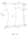
- stator vane 18 narrows in chord to a waist 36 of minimum chord length which is preferably disposed centrally between the root 28 and tip 30 along the longitudinal or radial span of the vane.
- the leading edge 24 is preferably tapered toward the waist 36 from both the root 28 and the tip 30, with a generally concave axial side view or projection as illustrated in Figure 1 defining a leading edge having a single scallop.
- the waist 36 is preferably disposed within a range of about 30%-70% of the longitudinal or radial span of the vane from its root 28. In the preferred embodiment illustrated, the waist 36 is disposed at about 50% span. And, the waist 36 may be up to about 30% less than the root and tip chords.
- the trailing edge 26 is preferably generally straight longitudinally or radially between the root and tip. In axial projection from either vane side, the trailing edge 26 appears straight in both the pressure and suction sides in the X-Z plane.
- stator vane 18 preferably narrows in chord solely from the leading edge 24 toward the trailing edge 26, with the trailing edge remaining straight in axial profile.
- the trailing edge 36 is configured to extend solely radially in axial elevation or projection without inclination with the leading edge. In this way, the waist 36 is defined solely by the tapered or scalloped leading edge 24, with the trailing edge being straight radially and without scallop.
- the vane narrows to its waist with a corresponding shortening of the chords from both endwalls for effecting a substantially uniform diffusion loading longitudinally or radially from root 28 to tip 30.
- a substantially uniform diffusion loading longitudinally or radially from root 28 to tip 30.
- the vane is selectively narrowed at the central waist to correspondingly increase loading and diffusion thereat without compromising loading and diffusion near the endwalls.
- the longitudinal loading distribution may be substantially uniform as indicated above, or may be slightly greater at vane midspan to ensure a smooth chord distribution. Compression efficiency is therefore increased by increasing diffusion in the vane central region, while correspondingly decreasing drag thereat.
- chord reduction is preferably effected at the front or leading edge of the airfoil instead of the trailing edge to increase aerodynamic sweep of the leading edge at the endwall bands.
- Aerodynamic sweep is a conventional parameter and the forward sweep effected at the vane leading edge near the inner and outer bands 32-34 further improves aerodynamic performance of the vane.
- the scalloped leading edge 24 may also be effected with a straight but inclined trailing edge.
- the trailing edge 26 may remain straight in axial projection but may be inclined toward the leading edge 24 from root to tip at an acute inclination angle A which may be up to about 10°.
- the inclination angle A is preferably constant between the root and tip.
- Compressor efficiency may be further increased, along with improved stall margin, by further modifying the vanes 18 as illustrated in tangential view or projection in the Y-Z plane illustrated in Figure 4.
- the Y-Z plane illustrated in Figure 4 is orthogonal or normal to the X-Z plane illustrated in Figure 1 for showing two projections of the same vanes 18 corresponding with tangential and axial projections, respectively.
- the vane suction side 22 is preferably bowed at an obtuse angle B between the trailing edge 26 and each of the root 28 and tip 30.
- the trailing edge 26 also defines a lean angle D with the radial axis in the tangential direction or view illustrated.
- vanes 18 are configured to turn and diffuse the airflow 12, flow separation of the air is a design consideration primarily on the vane suction side near the trailing edge.
- vane suction side In a conventional, generally radially straight stator vane, the vane suction side is generally normal to the corresponding endwalls and is subject to flow separation thereat.
- the resulting obtuse angles B can significantly reduce or eliminate undesirable flow separation at the endwalls or bands.
- a further increase in compressor efficiency and stall margin may be obtained therefrom.
- the individual vanes 18 are bowed primarily along their trailing edges 26 to create similar obtuse angles B at both the root 28 and tip 30.
- the lean angle D correspondingly varies over the longitudinal span of the vane to smoothly interconnect the oppositely inclined root and tip-portions at the trailing edge.
- the lean angle varies continuously between the root and tip.
- the bowed trailing edge illustrated in Figure 4 may be effected by varying the corresponding camber and stagger angle of each radial section, along with bowing the stacking axis 38 of the vane from a radial line, primarily in the tangential component thereof.
- the stacking axis for vanes is preferably the locus of mid-points of the camber lines of individual radial vane sections, which mid-points are typically radially aligned along the span of a vane.
- the tangential component of the stacking axis 38 is bowed and displaced from the radial span axis to effect the preferred bowed trailing edge of the vane.
- the scalloped leading edge 24 illustrated in Figure 1 is preferably used in combination with the bowed trailing edge 26 illustrated in Figure 4, preferably without one compromising the other.
- the combination thereof further enhances aerodynamic efficiency, and the reduction or elimination of undesirable flow separation at the endwalls.
- the same vane 18 illustrated in Figures 1 and 4 preferably includes both the scalloped leading edge 24 with the central waist 36 of minimum chord, and the trailing edge 26 bowed orthogonally therefrom.
- the trailing edge 26 is generally straight in the axial projection of the pressure and suction sides 20,22, as well as being bowed along the suction side 22 in the orthogonal tangential plane illustrated in Figure 4. This combination of the trailing edge 26 in two orthogonal planes permits the amount of trailing edge lean D to be maximized, with a substantially large obtuse angle B for further improving compressor efficiency and stall margin.
- the obtuse angle B may therefore be maximized within an exemplary range of about 100°-130°, with the 130° exemplary upper limit being chosen for manufacturing reasons as discussed hereinbelow.
- the large trailing edge bow cooperates with the scalloped leading edge with 3D synergy for maximizing the uniformity of diffusion loading longitudinally from the vane root 28 to tip 30. Uniform aerodynamic loading is effected also with a substantial reduction or elimination of flow separation between the vane suction side and corresponding endwalls at the trailing edge.
- the vane leading edge 24 is preferably substantially normal or perpendicular to the corresponding root 28 and tip 30 and extends primarily in the radial direction.
- leading edge 24 is generally straight at the root and tip in the tangential plane illustrated in Figure 4, which is orthogonal to the taper of the leading edge in the axial plane illustrated in Figure 1.
- each vane is tangentially bowed as discussed above, the leading edge portions of the vanes are relatively straight for maintaining longitudinal rigidity of the vanes for permitting their assembly with the corresponding bands.
- Such assembly is typically effected by stabbing the individual vanes into complementary apertures in the bands with sufficient force to effect an interference fit therewith.
- the individual vanes therefore require longitudinal stiffness to prevent buckling or longitudinal distortion under the considerable stabbing forces employed.
- the obtuse interface angle B illustrated in Figure 4 is preferred locally at the vane trailing edge, and preferably decreases in magnitude from the trailing edge toward the leading edge 24. At the leading edge, the interface angle B approaches 90°. in this way, a significant portion of each vane may maintain a normal or perpendicular orientation relative to its opposite root and tip for maintaining radial stiffness thereof and permitting stabbing assembly of the vanes with the bands. The bowing of each vane may thusly be limited to the trailing edge region for enhancing aerodynamic performance without compromising manufacturability.
- the scalloped and bowed stator vanes 18 illustrated in Figure 4 thusly enjoy improved aerodynamic performance with their supporting bands 32,34.
- the obtuse interface angle B is effected between the vane suction side 22 and the trailing edge 26 at both endwalls 32,34. Flow separation thereat is significantly reduced or eliminated, and more uniform aerodynamic loading of the vanes across their radial spans is effected for further improving efficiency.
- the scalloped and bowed features of the stator vanes may be used separately or in combination for maximizing efficiency and stall margin due to the synergistic combination thereof.
Landscapes
- Engineering & Computer Science (AREA)
- Mechanical Engineering (AREA)
- General Engineering & Computer Science (AREA)
- Chemical & Material Sciences (AREA)
- Materials Engineering (AREA)
- Physics & Mathematics (AREA)
- Ceramic Engineering (AREA)
- Geometry (AREA)
- Fluid Mechanics (AREA)
- Composite Materials (AREA)
- Structures Of Non-Positive Displacement Pumps (AREA)
Abstract
Description
Claims (10)
- A compressor stator vane (18) comprising pressure and suction sides (20,22) extending chordally between leading and trailing edges (24,26), and longitudinally between a root (28) and tip (30), and narrowing in chord to a waist 36 therebetween.
- A vane according to claim 1 wherein said leading edge (24) is tapered toward said waist (36) from said root (28) and from said tip (30).
- A vane according to claim 1 or claim 2 wherein said waist (36) is disposed within a range of about 30%-70% of longitudinal span from said root (28).
- A vane according to claim 1 or claim 2 wherein said trailing edge (26) is generally straight longitudinally between said root (28) and tip (30).
- A vane according to claim 2 wherein said chords shorten to said waist (36) for effecting a substantially uniform diffusion loading longitudinally from said root (28) to tip (30).
- A vane according to claim 1 or claim 2 wherein said suction side (22) is bowed at an obtuse angle between said trailing edge (26) and each of said root (28) and tip (30).
- A vane according to claim 6 wherein said trailing edge (26) is generally straight in said pressure and suction sides (20,22) orthogonal to said bow of said suction side (22) thereat.
- A vane according to claim 6 wherein said leading edge (24) is substantially normal to said root (28) and tip (30).
- A vane according to claim 6 further comprising an inner band (32) joined normal to said root (28), and an outer band (34) joined normal to said
- A compressor stator vane 18 comprising a scalloped leading edge (24) with a waist (36) of minimum chord, and a trailing edge (26) bowed orthogonally to said leading edge.
Applications Claiming Priority (2)
| Application Number | Priority Date | Filing Date | Title |
|---|---|---|---|
| US434344 | 1982-10-14 | ||
| US09/434,344 US6312219B1 (en) | 1999-11-05 | 1999-11-05 | Narrow waist vane |
Publications (3)
| Publication Number | Publication Date |
|---|---|
| EP1098092A2 true EP1098092A2 (en) | 2001-05-09 |
| EP1098092A3 EP1098092A3 (en) | 2002-06-12 |
| EP1098092B1 EP1098092B1 (en) | 2007-11-21 |
Family
ID=23723843
Family Applications (1)
| Application Number | Title | Priority Date | Filing Date |
|---|---|---|---|
| EP00307193A Expired - Lifetime EP1098092B1 (en) | 1999-11-05 | 2000-08-22 | Stator blade |
Country Status (6)
| Country | Link |
|---|---|
| US (1) | US6312219B1 (en) |
| EP (1) | EP1098092B1 (en) |
| JP (1) | JP5059991B2 (en) |
| DE (1) | DE60037170T2 (en) |
| ES (1) | ES2294996T3 (en) |
| RU (1) | RU2219377C2 (en) |
Cited By (38)
| Publication number | Priority date | Publication date | Assignee | Title |
|---|---|---|---|---|
| EP1462608A1 (en) * | 2003-03-27 | 2004-09-29 | Snecma Moteurs | Stator vane with double curvature |
| EP1508669A1 (en) * | 2003-08-19 | 2005-02-23 | Siemens Aktiengesellschaft | Stator vanes ring for a compressor and a turbine |
| EP1582696A1 (en) * | 2004-03-30 | 2005-10-05 | Siemens Aktiengesellschaft | Compressor vane and method of constructing a compressor vane |
| EP1707744A2 (en) * | 2005-03-07 | 2006-10-04 | The General Electric Company | Stator vane with inner and outer shroud |
| WO2007042522A1 (en) * | 2005-10-11 | 2007-04-19 | Alstom Technology Ltd | Turbo-machine blade |
| EP2133573A1 (en) | 2008-06-13 | 2009-12-16 | Siemens Aktiengesellschaft | Vane or blade for an axial flow compressor |
| GB2471152A (en) * | 2009-06-17 | 2010-12-22 | Dresser Rand Co | Use of Bowed Vanes to reduce Acoustic Signature |
| US8167548B2 (en) | 2007-11-09 | 2012-05-01 | Alstom Technology Ltd. | Steam turbine |
| EP2476862A1 (en) * | 2011-01-13 | 2012-07-18 | Alstom Technology Ltd | Vane for an axial flow turbomachine and corresponding turbomachine |
| WO2012134937A1 (en) * | 2011-03-25 | 2012-10-04 | General Electric Company | High camber stator vane |
| FR2977908A1 (en) * | 2011-07-13 | 2013-01-18 | Snecma | TURBINE DAWN |
| WO2015175056A2 (en) | 2014-02-19 | 2015-11-19 | United Technologies Corporation | Gas turbine engine airfoil |
| EP3168415A1 (en) * | 2015-11-12 | 2017-05-17 | Rolls-Royce plc | Compressor |
| CN106979177A (en) * | 2016-01-18 | 2017-07-25 | 通用电气公司 | Turbo-compressor stator |
| US9752439B2 (en) | 2014-02-19 | 2017-09-05 | United Technologies Corporation | Gas turbine engine airfoil |
| US9777580B2 (en) | 2014-02-19 | 2017-10-03 | United Technologies Corporation | Gas turbine engine airfoil |
| EP3290643A1 (en) * | 2016-09-02 | 2018-03-07 | United Technologies Corporation | Short inlet with low solidity fan exit guide vane arrangements |
| US10036257B2 (en) | 2014-02-19 | 2018-07-31 | United Technologies Corporation | Gas turbine engine airfoil |
| EP3404212A1 (en) * | 2017-05-16 | 2018-11-21 | Rolls-Royce plc | Compressor aerofoil member |
| US10184483B2 (en) | 2014-02-19 | 2019-01-22 | United Technologies Corporation | Gas turbine engine airfoil |
| US10309414B2 (en) | 2014-02-19 | 2019-06-04 | United Technologies Corporation | Gas turbine engine airfoil |
| US10352331B2 (en) | 2014-02-19 | 2019-07-16 | United Technologies Corporation | Gas turbine engine airfoil |
| US10358925B2 (en) | 2014-02-19 | 2019-07-23 | United Technologies Corporation | Gas turbine engine airfoil |
| US10370974B2 (en) | 2014-02-19 | 2019-08-06 | United Technologies Corporation | Gas turbine engine airfoil |
| US10385866B2 (en) | 2014-02-19 | 2019-08-20 | United Technologies Corporation | Gas turbine engine airfoil |
| US10393139B2 (en) | 2014-02-19 | 2019-08-27 | United Technologies Corporation | Gas turbine engine airfoil |
| US10422226B2 (en) | 2014-02-19 | 2019-09-24 | United Technologies Corporation | Gas turbine engine airfoil |
| US10495106B2 (en) | 2014-02-19 | 2019-12-03 | United Technologies Corporation | Gas turbine engine airfoil |
| US10502229B2 (en) | 2014-02-19 | 2019-12-10 | United Technologies Corporation | Gas turbine engine airfoil |
| US10519971B2 (en) | 2014-02-19 | 2019-12-31 | United Technologies Corporation | Gas turbine engine airfoil |
| US10550852B2 (en) | 2014-02-19 | 2020-02-04 | United Technologies Corporation | Gas turbine engine airfoil |
| US10557477B2 (en) | 2014-02-19 | 2020-02-11 | United Technologies Corporation | Gas turbine engine airfoil |
| US10570916B2 (en) | 2014-02-19 | 2020-02-25 | United Technologies Corporation | Gas turbine engine airfoil |
| US10570915B2 (en) | 2014-02-19 | 2020-02-25 | United Technologies Corporation | Gas turbine engine airfoil |
| US10584715B2 (en) | 2014-02-19 | 2020-03-10 | United Technologies Corporation | Gas turbine engine airfoil |
| US10590775B2 (en) | 2014-02-19 | 2020-03-17 | United Technologies Corporation | Gas turbine engine airfoil |
| US10605259B2 (en) | 2014-02-19 | 2020-03-31 | United Technologies Corporation | Gas turbine engine airfoil |
| US20250305447A1 (en) * | 2024-03-27 | 2025-10-02 | General Electric Company | Compact core arrangement for high bypass ratio gas turbine engine architecture |
Families Citing this family (38)
| Publication number | Priority date | Publication date | Assignee | Title |
|---|---|---|---|---|
| US6508630B2 (en) * | 2001-03-30 | 2003-01-21 | General Electric Company | Twisted stator vane |
| JP4786077B2 (en) * | 2001-08-10 | 2011-10-05 | 本田技研工業株式会社 | Turbine vane and method for manufacturing the same |
| GB2384276A (en) * | 2002-01-18 | 2003-07-23 | Alstom | Gas turbine low pressure stage |
| EP1642005B1 (en) * | 2003-07-09 | 2009-10-14 | Siemens Aktiengesellschaft | Turbine blade |
| CN101307781A (en) * | 2003-07-22 | 2008-11-19 | 奇鋐科技股份有限公司 | Wind direction outlet control device |
| US6996978B2 (en) * | 2004-05-05 | 2006-02-14 | Goerend David J | Torque converter stator |
| US8757965B2 (en) * | 2004-06-01 | 2014-06-24 | Volvo Aero Corporation | Gas turbine compression system and compressor structure |
| US7320575B2 (en) * | 2004-09-28 | 2008-01-22 | General Electric Company | Methods and apparatus for aerodynamically self-enhancing rotor blades |
| US7547186B2 (en) | 2004-09-28 | 2009-06-16 | Honeywell International Inc. | Nonlinearly stacked low noise turbofan stator |
| DE102004054752A1 (en) * | 2004-11-12 | 2006-05-18 | Rolls-Royce Deutschland Ltd & Co Kg | Blade of a flow machine with extended edge profile depth |
| EP1710397B1 (en) * | 2005-03-31 | 2014-06-11 | Kabushiki Kaisha Toshiba | Bowed nozzle vane |
| US7686567B2 (en) * | 2005-12-16 | 2010-03-30 | United Technologies Corporation | Airfoil embodying mixed loading conventions |
| FR2899270A1 (en) * | 2006-03-30 | 2007-10-05 | Snecma Sa | LOCALLY-SHAPED RECTIFIER RAM, RECTIFIER AREA, COMPRESSION STAGE, COMPRESSOR AND TURBOMACHINE COMPRISING SUCH A BLADE |
| US8292574B2 (en) | 2006-11-30 | 2012-10-23 | General Electric Company | Advanced booster system |
| US7967571B2 (en) * | 2006-11-30 | 2011-06-28 | General Electric Company | Advanced booster rotor blade |
| US8087884B2 (en) * | 2006-11-30 | 2012-01-03 | General Electric Company | Advanced booster stator vane |
| GB0704426D0 (en) * | 2007-03-08 | 2007-04-18 | Rolls Royce Plc | Aerofoil members for a turbomachine |
| WO2008123846A1 (en) * | 2007-04-03 | 2008-10-16 | Carrier Corporation | Outlet guide vanes for axial flow fans |
| DE102008060847B4 (en) * | 2008-12-06 | 2020-03-19 | MTU Aero Engines AG | Fluid machine |
| US8137062B2 (en) * | 2010-05-11 | 2012-03-20 | General Electric Company | Turbomachine nozzle |
| US8684698B2 (en) | 2011-03-25 | 2014-04-01 | General Electric Company | Compressor airfoil with tip dihedral |
| US8702398B2 (en) | 2011-03-25 | 2014-04-22 | General Electric Company | High camber compressor rotor blade |
| FR2983234B1 (en) * | 2011-11-29 | 2014-01-17 | Snecma | AUBE FOR TURBOMACHINE MONOBLOC AUBING DISK |
| EP2787181B1 (en) * | 2011-11-30 | 2019-01-09 | Mitsubishi Heavy Industries, Ltd. | Radial turbine |
| US8424313B1 (en) | 2012-01-31 | 2013-04-23 | United Technologies Corporation | Gas turbine engine mid turbine frame with flow turning features |
| US9115584B2 (en) * | 2012-04-24 | 2015-08-25 | General Electric Company | Resistive band for turbomachine blade |
| CA2903738A1 (en) * | 2013-03-07 | 2014-09-12 | Rolls-Royce Canada, Ltd. | Gas turbine engine comprising an outboard insertion system of vanes and corresponding assembling method |
| EP3008290B1 (en) * | 2013-06-14 | 2018-10-31 | United Technologies Corporation | Turbine vane with variable trailing edge inner radius |
| EP2824277B1 (en) | 2013-07-12 | 2016-03-23 | MTU Aero Engines GmbH | Gas turbine stage |
| EP2921647A1 (en) * | 2014-03-20 | 2015-09-23 | Alstom Technology Ltd | Gas turbine blade comprising bended leading and trailing edges |
| DE102014205226A1 (en) | 2014-03-20 | 2015-09-24 | Rolls-Royce Deutschland Ltd & Co Kg | Blade row group |
| EP3186484B1 (en) | 2014-08-29 | 2019-06-05 | Siemens Aktiengesellschaft | Gas turbine engine |
| JP6421091B2 (en) | 2015-07-30 | 2018-11-07 | 三菱日立パワーシステムズ株式会社 | Axial flow compressor, gas turbine including the same, and stationary blade of axial flow compressor |
| KR101901682B1 (en) | 2017-06-20 | 2018-09-27 | 두산중공업 주식회사 | J Type Cantilevered Vane And Gas Turbine Having The Same |
| KR101997985B1 (en) | 2017-10-27 | 2019-07-08 | 두산중공업 주식회사 | Modified J Type Cantilevered Vane And Gas Turbine Having The Same |
| US12601283B2 (en) | 2019-04-08 | 2026-04-14 | Pratt & Whitney Canada Corp. | Turbine exhaust case mixer |
| US11286779B2 (en) * | 2020-06-03 | 2022-03-29 | Honeywell International Inc. | Characteristic distribution for rotor blade of booster rotor |
| DE102022103319A1 (en) | 2022-02-11 | 2023-08-17 | MTU Aero Engines AG | Guide vane for a turbomachine |
Family Cites Families (23)
| Publication number | Priority date | Publication date | Assignee | Title |
|---|---|---|---|---|
| FR1037610A (en) * | 1950-03-03 | 1953-09-22 | Rolls Royce | Improvements to guide vane assemblies for annular fluid conduits |
| US2801790A (en) * | 1950-06-21 | 1957-08-06 | United Aircraft Corp | Compressor blading |
| DE2046486C3 (en) * | 1970-09-21 | 1974-03-07 | Fa. Willi Seeber, Kardaun, Bozen (Italien) | Impeller for fan |
| JPS5925091B2 (en) * | 1979-11-09 | 1984-06-14 | 株式会社日立製作所 | turbine stator blade |
| US4682935A (en) | 1983-12-12 | 1987-07-28 | General Electric Company | Bowed turbine blade |
| US4585395A (en) | 1983-12-12 | 1986-04-29 | General Electric Company | Gas turbine engine blade |
| SU1370320A1 (en) * | 1986-06-23 | 1988-01-30 | И.К. Попов | Axial fan impeller |
| US4726737A (en) | 1986-10-28 | 1988-02-23 | United Technologies Corporation | Reduced loss swept supersonic fan blade |
| US4784575A (en) | 1986-11-19 | 1988-11-15 | General Electric Company | Counterrotating aircraft propulsor blades |
| US5246339A (en) * | 1988-06-08 | 1993-09-21 | Abb Flakt Ab | Guide vane for an axial fan |
| US5088892A (en) * | 1990-02-07 | 1992-02-18 | United Technologies Corporation | Bowed airfoil for the compression section of a rotary machine |
| JP2753382B2 (en) * | 1990-09-17 | 1998-05-20 | 株式会社日立製作所 | Axial flow turbine vane device and axial flow turbine |
| FR2671140B1 (en) * | 1990-12-27 | 1995-01-13 | Snecma | RECTIFIER BLADE FOR TURBOMACHINE COMPRESSOR. |
| US5167489A (en) | 1991-04-15 | 1992-12-01 | General Electric Company | Forward swept rotor blade |
| US5641268A (en) | 1991-09-17 | 1997-06-24 | Rolls-Royce Plc | Aerofoil members for gas turbine engines |
| DE4228879A1 (en) | 1992-08-29 | 1994-03-03 | Asea Brown Boveri | Turbine with axial flow |
| JP3631271B2 (en) * | 1993-11-19 | 2005-03-23 | ユナイテッド テクノロジーズ コーポレイション | Inner shroud integrated stator vane structure |
| JPH08114199A (en) * | 1994-10-19 | 1996-05-07 | Hitachi Ltd | Axial compressor |
| JPH0925897A (en) * | 1995-07-11 | 1997-01-28 | Mitsubishi Heavy Ind Ltd | Stator blade for axial compressor |
| US5642985A (en) | 1995-11-17 | 1997-07-01 | United Technologies Corporation | Swept turbomachinery blade |
| JPH10103002A (en) * | 1996-09-30 | 1998-04-21 | Toshiba Corp | Blade for axial flow fluid machine |
| JP3604533B2 (en) * | 1997-05-30 | 2004-12-22 | 株式会社東芝 | Wing for axial compressor |
| US6039542A (en) * | 1997-12-24 | 2000-03-21 | General Electric Company | Panel damped hybrid blade |
-
1999
- 1999-11-05 US US09/434,344 patent/US6312219B1/en not_active Expired - Lifetime
-
2000
- 2000-08-22 ES ES00307193T patent/ES2294996T3/en not_active Expired - Lifetime
- 2000-08-22 DE DE60037170T patent/DE60037170T2/en not_active Expired - Lifetime
- 2000-08-22 EP EP00307193A patent/EP1098092B1/en not_active Expired - Lifetime
- 2000-09-04 RU RU2000122997/06A patent/RU2219377C2/en not_active IP Right Cessation
- 2000-09-04 JP JP2000266368A patent/JP5059991B2/en not_active Expired - Fee Related
Cited By (68)
| Publication number | Priority date | Publication date | Assignee | Title |
|---|---|---|---|---|
| EP1462608A1 (en) * | 2003-03-27 | 2004-09-29 | Snecma Moteurs | Stator vane with double curvature |
| FR2853022A1 (en) * | 2003-03-27 | 2004-10-01 | Snecma Moteurs | DOUBLE CURVED RECTIFIER BLADE |
| US7121792B1 (en) | 2003-03-27 | 2006-10-17 | Snecma Moteurs | Nozzle vane with two slopes |
| EP1508669A1 (en) * | 2003-08-19 | 2005-02-23 | Siemens Aktiengesellschaft | Stator vanes ring for a compressor and a turbine |
| EP1582696A1 (en) * | 2004-03-30 | 2005-10-05 | Siemens Aktiengesellschaft | Compressor vane and method of constructing a compressor vane |
| EP1707744A2 (en) * | 2005-03-07 | 2006-10-04 | The General Electric Company | Stator vane with inner and outer shroud |
| US8221065B2 (en) | 2005-10-11 | 2012-07-17 | Alstom Technology Ltd | Turbomachine blade with variable chord length |
| WO2007042522A1 (en) * | 2005-10-11 | 2007-04-19 | Alstom Technology Ltd | Turbo-machine blade |
| US8167548B2 (en) | 2007-11-09 | 2012-05-01 | Alstom Technology Ltd. | Steam turbine |
| US8678757B2 (en) | 2008-06-13 | 2014-03-25 | Siemens Aktiengesellschaft | Vane or blade for an axial flow compressor |
| CN102066767B (en) * | 2008-06-13 | 2013-07-17 | 西门子公司 | Vane or blade for an axial flow compressor |
| CN102066767A (en) * | 2008-06-13 | 2011-05-18 | 西门子公司 | Vane or blade for an axial flow compressor |
| WO2009149970A1 (en) * | 2008-06-13 | 2009-12-17 | Siemens Aktiengesellschaft | Vane or blade for an axial flow compressor |
| EP2133573A1 (en) | 2008-06-13 | 2009-12-16 | Siemens Aktiengesellschaft | Vane or blade for an axial flow compressor |
| GB2471152A (en) * | 2009-06-17 | 2010-12-22 | Dresser Rand Co | Use of Bowed Vanes to reduce Acoustic Signature |
| GB2471152B (en) * | 2009-06-17 | 2016-08-10 | Dresser-Rand Company | Use of bowed nozzle vanes to reduce acoustic signature |
| EP2476862A1 (en) * | 2011-01-13 | 2012-07-18 | Alstom Technology Ltd | Vane for an axial flow turbomachine and corresponding turbomachine |
| US8894364B2 (en) | 2011-01-13 | 2014-11-25 | Alstom Technology Ltd. | Aerofoil blade for an axial flow turbomachine |
| CN102587997A (en) * | 2011-01-13 | 2012-07-18 | 阿尔斯通技术有限公司 | Vane for an axial flow turbomachine and corresponding turbomachine |
| CN103443402A (en) * | 2011-03-25 | 2013-12-11 | 通用电气公司 | High arc stator guide vanes |
| WO2012134937A1 (en) * | 2011-03-25 | 2012-10-04 | General Electric Company | High camber stator vane |
| US9074483B2 (en) | 2011-03-25 | 2015-07-07 | General Electric Company | High camber stator vane |
| CN103443402B (en) * | 2011-03-25 | 2016-01-27 | 通用电气公司 | High arc stator guide vanes |
| FR2977908A1 (en) * | 2011-07-13 | 2013-01-18 | Snecma | TURBINE DAWN |
| US9022744B2 (en) | 2011-07-13 | 2015-05-05 | Snecma | Turbine engine blade |
| US10036257B2 (en) | 2014-02-19 | 2018-07-31 | United Technologies Corporation | Gas turbine engine airfoil |
| US10495106B2 (en) | 2014-02-19 | 2019-12-03 | United Technologies Corporation | Gas turbine engine airfoil |
| US11867195B2 (en) | 2014-02-19 | 2024-01-09 | Rtx Corporation | Gas turbine engine airfoil |
| US11767856B2 (en) | 2014-02-19 | 2023-09-26 | Rtx Corporation | Gas turbine engine airfoil |
| US11408436B2 (en) | 2014-02-19 | 2022-08-09 | Raytheon Technologies Corporation | Gas turbine engine airfoil |
| US9752439B2 (en) | 2014-02-19 | 2017-09-05 | United Technologies Corporation | Gas turbine engine airfoil |
| US9777580B2 (en) | 2014-02-19 | 2017-10-03 | United Technologies Corporation | Gas turbine engine airfoil |
| US11391294B2 (en) | 2014-02-19 | 2022-07-19 | Raytheon Technologies Corporation | Gas turbine engine airfoil |
| US9988908B2 (en) | 2014-02-19 | 2018-06-05 | United Technologies Corporation | Gas turbine engine airfoil |
| WO2015175056A2 (en) | 2014-02-19 | 2015-11-19 | United Technologies Corporation | Gas turbine engine airfoil |
| US11209013B2 (en) | 2014-02-19 | 2021-12-28 | Raytheon Technologies Corporation | Gas turbine engine airfoil |
| US10184483B2 (en) | 2014-02-19 | 2019-01-22 | United Technologies Corporation | Gas turbine engine airfoil |
| US10309414B2 (en) | 2014-02-19 | 2019-06-04 | United Technologies Corporation | Gas turbine engine airfoil |
| US10352331B2 (en) | 2014-02-19 | 2019-07-16 | United Technologies Corporation | Gas turbine engine airfoil |
| US10358925B2 (en) | 2014-02-19 | 2019-07-23 | United Technologies Corporation | Gas turbine engine airfoil |
| US10370974B2 (en) | 2014-02-19 | 2019-08-06 | United Technologies Corporation | Gas turbine engine airfoil |
| US10385866B2 (en) | 2014-02-19 | 2019-08-20 | United Technologies Corporation | Gas turbine engine airfoil |
| US10393139B2 (en) | 2014-02-19 | 2019-08-27 | United Technologies Corporation | Gas turbine engine airfoil |
| US10422226B2 (en) | 2014-02-19 | 2019-09-24 | United Technologies Corporation | Gas turbine engine airfoil |
| US10465702B2 (en) | 2014-02-19 | 2019-11-05 | United Technologies Corporation | Gas turbine engine airfoil |
| US11193496B2 (en) | 2014-02-19 | 2021-12-07 | Raytheon Technologies Corporation | Gas turbine engine airfoil |
| EP3108122A4 (en) * | 2014-02-19 | 2017-03-01 | United Technologies Corporation | Gas turbine engine airfoil |
| US10502229B2 (en) | 2014-02-19 | 2019-12-10 | United Technologies Corporation | Gas turbine engine airfoil |
| US10519971B2 (en) | 2014-02-19 | 2019-12-31 | United Technologies Corporation | Gas turbine engine airfoil |
| US11193497B2 (en) | 2014-02-19 | 2021-12-07 | Raytheon Technologies Corporation | Gas turbine engine airfoil |
| US10550852B2 (en) | 2014-02-19 | 2020-02-04 | United Technologies Corporation | Gas turbine engine airfoil |
| US10557477B2 (en) | 2014-02-19 | 2020-02-11 | United Technologies Corporation | Gas turbine engine airfoil |
| US10570916B2 (en) | 2014-02-19 | 2020-02-25 | United Technologies Corporation | Gas turbine engine airfoil |
| US10570915B2 (en) | 2014-02-19 | 2020-02-25 | United Technologies Corporation | Gas turbine engine airfoil |
| US10584715B2 (en) | 2014-02-19 | 2020-03-10 | United Technologies Corporation | Gas turbine engine airfoil |
| US10590775B2 (en) | 2014-02-19 | 2020-03-17 | United Technologies Corporation | Gas turbine engine airfoil |
| US10605259B2 (en) | 2014-02-19 | 2020-03-31 | United Technologies Corporation | Gas turbine engine airfoil |
| US10890195B2 (en) | 2014-02-19 | 2021-01-12 | Raytheon Technologies Corporation | Gas turbine engine airfoil |
| US10914315B2 (en) | 2014-02-19 | 2021-02-09 | Raytheon Technologies Corporation | Gas turbine engine airfoil |
| US11041507B2 (en) | 2014-02-19 | 2021-06-22 | Raytheon Technologies Corporation | Gas turbine engine airfoil |
| US10495095B2 (en) | 2015-11-12 | 2019-12-03 | Rolls-Royce Plc | Multistage compressor with aerofoil portion profiled in a spanwise direction |
| EP3168415A1 (en) * | 2015-11-12 | 2017-05-17 | Rolls-Royce plc | Compressor |
| EP3196409A3 (en) * | 2016-01-18 | 2017-08-23 | General Electric Company | Turbine compressor vane |
| CN106979177A (en) * | 2016-01-18 | 2017-07-25 | 通用电气公司 | Turbo-compressor stator |
| US10526894B1 (en) | 2016-09-02 | 2020-01-07 | United Technologies Corporation | Short inlet with low solidity fan exit guide vane arrangements |
| EP3290643A1 (en) * | 2016-09-02 | 2018-03-07 | United Technologies Corporation | Short inlet with low solidity fan exit guide vane arrangements |
| EP3404212A1 (en) * | 2017-05-16 | 2018-11-21 | Rolls-Royce plc | Compressor aerofoil member |
| US20250305447A1 (en) * | 2024-03-27 | 2025-10-02 | General Electric Company | Compact core arrangement for high bypass ratio gas turbine engine architecture |
Also Published As
| Publication number | Publication date |
|---|---|
| EP1098092B1 (en) | 2007-11-21 |
| RU2219377C2 (en) | 2003-12-20 |
| EP1098092A3 (en) | 2002-06-12 |
| DE60037170T2 (en) | 2008-09-18 |
| ES2294996T3 (en) | 2008-04-16 |
| US6312219B1 (en) | 2001-11-06 |
| JP5059991B2 (en) | 2012-10-31 |
| DE60037170D1 (en) | 2008-01-03 |
| JP2001132696A (en) | 2001-05-18 |
Similar Documents
| Publication | Publication Date | Title |
|---|---|---|
| EP1098092B1 (en) | Stator blade | |
| CA2326424C (en) | Double bowed compressor airfoil | |
| US6299412B1 (en) | Bowed compressor airfoil | |
| CA2613601C (en) | A turbine assembly for a gas turbine engine and method of manufacturing the same | |
| CA2613787C (en) | Gas turbine engines including multi-curve stator vanes and methods of assembling the same | |
| CA2333843C (en) | Fluted compressor flowpath | |
| JP3578769B2 (en) | Flow orientation assembly for the compression region of rotating machinery | |
| EP1930600B1 (en) | Advanced booster stator vane | |
| EP1930598B1 (en) | Advanced booster rotor blade | |
| US6508630B2 (en) | Twisted stator vane | |
| EP1930599B1 (en) | Advanced booster system | |
| US12320274B2 (en) | Compressor stator with leading edge fillet | |
| CA2950715A1 (en) | Method and system for improving turbine blade performance |
Legal Events
| Date | Code | Title | Description |
|---|---|---|---|
| PUAI | Public reference made under article 153(3) epc to a published international application that has entered the european phase |
Free format text: ORIGINAL CODE: 0009012 |
|
| AK | Designated contracting states |
Kind code of ref document: A2 Designated state(s): AT BE CH CY DE DK ES FI FR GB GR IE IT LI LU MC NL PT SE |
|
| AX | Request for extension of the european patent |
Free format text: AL;LT;LV;MK;RO;SI |
|
| PUAL | Search report despatched |
Free format text: ORIGINAL CODE: 0009013 |
|
| AK | Designated contracting states |
Kind code of ref document: A3 Designated state(s): AT BE CH CY DE DK ES FI FR GB GR IE IT LI LU MC NL PT SE |
|
| AX | Request for extension of the european patent |
Free format text: AL;LT;LV;MK;RO;SI |
|
| RIC1 | Information provided on ipc code assigned before grant |
Free format text: 7F 04D 29/54 A, 7F 01D 5/14 B |
|
| 17P | Request for examination filed |
Effective date: 20021212 |
|
| AKX | Designation fees paid |
Designated state(s): AT BE CH CY DE DK ES FI FR GB GR IE IT LI LU MC NL PT SE |
|
| GRAP | Despatch of communication of intention to grant a patent |
Free format text: ORIGINAL CODE: EPIDOSNIGR1 |
|
| GRAS | Grant fee paid |
Free format text: ORIGINAL CODE: EPIDOSNIGR3 |
|
| GRAA | (expected) grant |
Free format text: ORIGINAL CODE: 0009210 |
|
| AK | Designated contracting states |
Kind code of ref document: B1 Designated state(s): AT BE CH CY DE DK ES FI FR GB GR IE IT LI LU MC NL PT SE |
|
| REG | Reference to a national code |
Ref country code: GB Ref legal event code: FG4D |
|
| REG | Reference to a national code |
Ref country code: IE Ref legal event code: FG4D |
|
| REG | Reference to a national code |
Ref country code: CH Ref legal event code: EP |
|
| REF | Corresponds to: |
Ref document number: 60037170 Country of ref document: DE Date of ref document: 20080103 Kind code of ref document: P |
|
| REG | Reference to a national code |
Ref country code: SE Ref legal event code: TRGR |
|
| REG | Reference to a national code |
Ref country code: ES Ref legal event code: FG2A Ref document number: 2294996 Country of ref document: ES Kind code of ref document: T3 |
|
| PG25 | Lapsed in a contracting state [announced via postgrant information from national office to epo] |
Ref country code: LI Free format text: LAPSE BECAUSE OF FAILURE TO SUBMIT A TRANSLATION OF THE DESCRIPTION OR TO PAY THE FEE WITHIN THE PRESCRIBED TIME-LIMIT Effective date: 20071121 Ref country code: NL Free format text: LAPSE BECAUSE OF FAILURE TO SUBMIT A TRANSLATION OF THE DESCRIPTION OR TO PAY THE FEE WITHIN THE PRESCRIBED TIME-LIMIT Effective date: 20071121 Ref country code: CH Free format text: LAPSE BECAUSE OF FAILURE TO SUBMIT A TRANSLATION OF THE DESCRIPTION OR TO PAY THE FEE WITHIN THE PRESCRIBED TIME-LIMIT Effective date: 20071121 |
|
| NLV1 | Nl: lapsed or annulled due to failure to fulfill the requirements of art. 29p and 29m of the patents act | ||
| PG25 | Lapsed in a contracting state [announced via postgrant information from national office to epo] |
Ref country code: FI Free format text: LAPSE BECAUSE OF FAILURE TO SUBMIT A TRANSLATION OF THE DESCRIPTION OR TO PAY THE FEE WITHIN THE PRESCRIBED TIME-LIMIT Effective date: 20071121 |
|
| REG | Reference to a national code |
Ref country code: CH Ref legal event code: PL |
|
| PG25 | Lapsed in a contracting state [announced via postgrant information from national office to epo] |
Ref country code: AT Free format text: LAPSE BECAUSE OF FAILURE TO SUBMIT A TRANSLATION OF THE DESCRIPTION OR TO PAY THE FEE WITHIN THE PRESCRIBED TIME-LIMIT Effective date: 20071121 |
|
| ET | Fr: translation filed | ||
| PG25 | Lapsed in a contracting state [announced via postgrant information from national office to epo] |
Ref country code: DK Free format text: LAPSE BECAUSE OF FAILURE TO SUBMIT A TRANSLATION OF THE DESCRIPTION OR TO PAY THE FEE WITHIN THE PRESCRIBED TIME-LIMIT Effective date: 20071121 |
|
| PG25 | Lapsed in a contracting state [announced via postgrant information from national office to epo] |
Ref country code: BE Free format text: LAPSE BECAUSE OF FAILURE TO SUBMIT A TRANSLATION OF THE DESCRIPTION OR TO PAY THE FEE WITHIN THE PRESCRIBED TIME-LIMIT Effective date: 20071121 |
|
| PLBI | Opposition filed |
Free format text: ORIGINAL CODE: 0009260 |
|
| PLAX | Notice of opposition and request to file observation + time limit sent |
Free format text: ORIGINAL CODE: EPIDOSNOBS2 |
|
| PG25 | Lapsed in a contracting state [announced via postgrant information from national office to epo] |
Ref country code: PT Free format text: LAPSE BECAUSE OF FAILURE TO SUBMIT A TRANSLATION OF THE DESCRIPTION OR TO PAY THE FEE WITHIN THE PRESCRIBED TIME-LIMIT Effective date: 20080421 |
|
| 26 | Opposition filed |
Opponent name: MAN TURBO AG Effective date: 20080819 |
|
| PG25 | Lapsed in a contracting state [announced via postgrant information from national office to epo] |
Ref country code: GR Free format text: LAPSE BECAUSE OF FAILURE TO SUBMIT A TRANSLATION OF THE DESCRIPTION OR TO PAY THE FEE WITHIN THE PRESCRIBED TIME-LIMIT Effective date: 20080222 |
|
| PLAF | Information modified related to communication of a notice of opposition and request to file observations + time limit |
Free format text: ORIGINAL CODE: EPIDOSCOBS2 |
|
| PG25 | Lapsed in a contracting state [announced via postgrant information from national office to epo] |
Ref country code: MC Free format text: LAPSE BECAUSE OF NON-PAYMENT OF DUE FEES Effective date: 20080831 |
|
| PLBB | Reply of patent proprietor to notice(s) of opposition received |
Free format text: ORIGINAL CODE: EPIDOSNOBS3 |
|
| PLAB | Opposition data, opponent's data or that of the opponent's representative modified |
Free format text: ORIGINAL CODE: 0009299OPPO |
|
| R26 | Opposition filed (corrected) |
Opponent name: MAN TURBO AG Effective date: 20080819 |
|
| PG25 | Lapsed in a contracting state [announced via postgrant information from national office to epo] |
Ref country code: CY Free format text: LAPSE BECAUSE OF FAILURE TO SUBMIT A TRANSLATION OF THE DESCRIPTION OR TO PAY THE FEE WITHIN THE PRESCRIBED TIME-LIMIT Effective date: 20071121 Ref country code: IE Free format text: LAPSE BECAUSE OF NON-PAYMENT OF DUE FEES Effective date: 20080822 |
|
| PG25 | Lapsed in a contracting state [announced via postgrant information from national office to epo] |
Ref country code: LU Free format text: LAPSE BECAUSE OF NON-PAYMENT OF DUE FEES Effective date: 20080822 |
|
| PLAB | Opposition data, opponent's data or that of the opponent's representative modified |
Free format text: ORIGINAL CODE: 0009299OPPO |
|
| R26 | Opposition filed (corrected) |
Opponent name: MAN TURBO AG Effective date: 20080819 |
|
| PLAB | Opposition data, opponent's data or that of the opponent's representative modified |
Free format text: ORIGINAL CODE: 0009299OPPO |
|
| R26 | Opposition filed (corrected) |
Opponent name: MAN DIESEL & TURBO SE Effective date: 20080819 |
|
| PLCK | Communication despatched that opposition was rejected |
Free format text: ORIGINAL CODE: EPIDOSNREJ1 |
|
| PLBN | Opposition rejected |
Free format text: ORIGINAL CODE: 0009273 |
|
| STAA | Information on the status of an ep patent application or granted ep patent |
Free format text: STATUS: OPPOSITION REJECTED |
|
| 27O | Opposition rejected |
Effective date: 20111011 |
|
| REG | Reference to a national code |
Ref country code: DE Ref legal event code: R100 Ref document number: 60037170 Country of ref document: DE Effective date: 20111011 |
|
| REG | Reference to a national code |
Ref country code: FR Ref legal event code: PLFP Year of fee payment: 17 |
|
| PGFP | Annual fee paid to national office [announced via postgrant information from national office to epo] |
Ref country code: GB Payment date: 20160830 Year of fee payment: 17 Ref country code: DE Payment date: 20160826 Year of fee payment: 17 Ref country code: IT Payment date: 20160824 Year of fee payment: 17 |
|
| PGFP | Annual fee paid to national office [announced via postgrant information from national office to epo] |
Ref country code: FR Payment date: 20160825 Year of fee payment: 17 Ref country code: SE Payment date: 20160829 Year of fee payment: 17 |
|
| PGFP | Annual fee paid to national office [announced via postgrant information from national office to epo] |
Ref country code: ES Payment date: 20160826 Year of fee payment: 17 |
|
| REG | Reference to a national code |
Ref country code: DE Ref legal event code: R119 Ref document number: 60037170 Country of ref document: DE |
|
| GBPC | Gb: european patent ceased through non-payment of renewal fee |
Effective date: 20170822 |
|
| PG25 | Lapsed in a contracting state [announced via postgrant information from national office to epo] |
Ref country code: SE Free format text: LAPSE BECAUSE OF NON-PAYMENT OF DUE FEES Effective date: 20170823 |
|
| REG | Reference to a national code |
Ref country code: FR Ref legal event code: ST Effective date: 20180430 |
|
| PG25 | Lapsed in a contracting state [announced via postgrant information from national office to epo] |
Ref country code: DE Free format text: LAPSE BECAUSE OF NON-PAYMENT OF DUE FEES Effective date: 20180301 Ref country code: GB Free format text: LAPSE BECAUSE OF NON-PAYMENT OF DUE FEES Effective date: 20170822 |
|
| PG25 | Lapsed in a contracting state [announced via postgrant information from national office to epo] |
Ref country code: IT Free format text: LAPSE BECAUSE OF NON-PAYMENT OF DUE FEES Effective date: 20170822 Ref country code: FR Free format text: LAPSE BECAUSE OF NON-PAYMENT OF DUE FEES Effective date: 20170831 |
|
| REG | Reference to a national code |
Ref country code: ES Ref legal event code: FD2A Effective date: 20181024 |
|
| PG25 | Lapsed in a contracting state [announced via postgrant information from national office to epo] |
Ref country code: ES Free format text: LAPSE BECAUSE OF NON-PAYMENT OF DUE FEES Effective date: 20170823 |