EP1098068A2 - Striated cooling hole - Google Patents
Striated cooling hole Download PDFInfo
- Publication number
- EP1098068A2 EP1098068A2 EP00309704A EP00309704A EP1098068A2 EP 1098068 A2 EP1098068 A2 EP 1098068A2 EP 00309704 A EP00309704 A EP 00309704A EP 00309704 A EP00309704 A EP 00309704A EP 1098068 A2 EP1098068 A2 EP 1098068A2
- Authority
- EP
- European Patent Office
- Prior art keywords
- hole
- striated
- airfoil
- wall
- holes
- Prior art date
- Legal status (The legal status is an assumption and is not a legal conclusion. Google has not performed a legal analysis and makes no representation as to the accuracy of the status listed.)
- Withdrawn
Links
Images


Classifications
-
- B—PERFORMING OPERATIONS; TRANSPORTING
- B23—MACHINE TOOLS; METAL-WORKING NOT OTHERWISE PROVIDED FOR
- B23H—WORKING OF METAL BY THE ACTION OF A HIGH CONCENTRATION OF ELECTRIC CURRENT ON A WORKPIECE USING AN ELECTRODE WHICH TAKES THE PLACE OF A TOOL; SUCH WORKING COMBINED WITH OTHER FORMS OF WORKING OF METAL
- B23H9/00—Machining specially adapted for treating particular metal objects or for obtaining special effects or results on metal objects
- B23H9/10—Working turbine blades or nozzles
-
- B—PERFORMING OPERATIONS; TRANSPORTING
- B23—MACHINE TOOLS; METAL-WORKING NOT OTHERWISE PROVIDED FOR
- B23H—WORKING OF METAL BY THE ACTION OF A HIGH CONCENTRATION OF ELECTRIC CURRENT ON A WORKPIECE USING AN ELECTRODE WHICH TAKES THE PLACE OF A TOOL; SUCH WORKING COMBINED WITH OTHER FORMS OF WORKING OF METAL
- B23H9/00—Machining specially adapted for treating particular metal objects or for obtaining special effects or results on metal objects
- B23H9/14—Making holes
- B23H9/16—Making holes using an electrolytic jet
-
- F—MECHANICAL ENGINEERING; LIGHTING; HEATING; WEAPONS; BLASTING
- F01—MACHINES OR ENGINES IN GENERAL; ENGINE PLANTS IN GENERAL; STEAM ENGINES
- F01D—NON-POSITIVE DISPLACEMENT MACHINES OR ENGINES, e.g. STEAM TURBINES
- F01D5/00—Blades; Blade-carrying members; Heating, heat-insulating, cooling or antivibration means on the blades or the members
- F01D5/12—Blades
- F01D5/14—Form or construction
- F01D5/18—Hollow blades, i.e. blades with cooling or heating channels or cavities; Heating, heat-insulating or cooling means on blades
- F01D5/186—Film cooling
-
- F—MECHANICAL ENGINEERING; LIGHTING; HEATING; WEAPONS; BLASTING
- F05—INDEXING SCHEMES RELATING TO ENGINES OR PUMPS IN VARIOUS SUBCLASSES OF CLASSES F01-F04
- F05D—INDEXING SCHEME FOR ASPECTS RELATING TO NON-POSITIVE-DISPLACEMENT MACHINES OR ENGINES, GAS-TURBINES OR JET-PROPULSION PLANTS
- F05D2260/00—Function
- F05D2260/20—Heat transfer, e.g. cooling
- F05D2260/221—Improvement of heat transfer
- F05D2260/2212—Improvement of heat transfer by creating turbulence
-
- Y—GENERAL TAGGING OF NEW TECHNOLOGICAL DEVELOPMENTS; GENERAL TAGGING OF CROSS-SECTIONAL TECHNOLOGIES SPANNING OVER SEVERAL SECTIONS OF THE IPC; TECHNICAL SUBJECTS COVERED BY FORMER USPC CROSS-REFERENCE ART COLLECTIONS [XRACs] AND DIGESTS
- Y02—TECHNOLOGIES OR APPLICATIONS FOR MITIGATION OR ADAPTATION AGAINST CLIMATE CHANGE
- Y02T—CLIMATE CHANGE MITIGATION TECHNOLOGIES RELATED TO TRANSPORTATION
- Y02T50/00—Aeronautics or air transport
- Y02T50/60—Efficient propulsion technologies, e.g. for aircraft
Definitions
- the present invention relates generally to gas turbine engines, and, more specifically, to turbine flow paths therein.
- air is pressurized in a compressor and mixed with fuel and ignited in a combustor for generating hot combustion gases.
- the gases flow through turbine stages including stator vanes and rotor blades which extract energy from the gases for powering the compressor and producing power for propelling an aircraft in flight for example.
- the turbine vanes and blades include airfoils which are bathed in the hot combustion gases during operation, and are therefore typically cooled. Airfoil cooling is effected by bleeding a portion of pressurized air from the compressor and channeling it through the airfoils in various manners of cooling thereof. Each airfoil may have one or more internal cooling channels which distribute the cooling air therethrough, which is then discharged from the airfoil through various outlet holes formed through the wall thereof.
- Trailing edge cooling is particularly problematic in view of the relative thinness of the airfoil thereat.
- An airfoil includes pressure and suction sides which extend from root to tip, and are joined at opposite leading and trailing edges. The pressure and suction sides converge to the trailing edge which may be about 30 mils (0.76 mm) thick or less.
- a typical trailing edge cooling design includes a row of axially extending discharge holes spaced apart radially along the longitudinal span of the airfoil. In view of the relative thinness of the airfoil trailing edge, this region of the airfoil is typically solid except for the trailing edge discharge holes typically centered in the wall between the opposite pressure and suction sides.
- the trailing edge holes extend axially forwardly to a common supply channel in which compressor bleed air is channeled for providing a coolant. The coolant air is discharged through the trailing edge holes for cooling the trailing edge region by internal convection.
- the trailing edge cooling holes must necessarily have small diameters to fit within the narrow width of the trailing edge wall.
- the holes are correspondingly relatively long, with a length-to-diameter ratio up to about 50, for example.
- a turbine wall having a striated discharge hole.
- the striated hole may comprise alternating annular grooves and lands.
- the grooves may be undercut adjoining lands at corresponding cusps.
- the grooves and lands may be coaxially aligned, with a collective length greater than a diameter of the hole.
- Grooves may be axially elongated.
- Each of the grooves may be circumferentially continuous between adjoining lands.
- the striated hole may further comprise an inlet disposed inside the wall and an outlet disposed outside the wall.
- a method of making the above described wall comprising: forming a plain hole through the wall; electrically insulating the plain hole at locations corresponding with the lands; and electrically eroding the plain hole at locations corresponding with the grooves.
- the hole insulating may comprise: coating the plain hole with an electrically insulating coating; and stripping the coating at the groove locations for retaining the electrically insulated land locations.
- the coating may be stripped at the groove locations by scratching the coating thereat to expose wall material therebelow.
- the scratching may comprise: rotating a flexible wire inside a tube disposed inside the hole; and extending a tip of the wire from a tip of the tube to circumferentially scratch the coating under centrifugal force.
- the method may further comprise axially translating the wire inside the hole as the wire rotates for scratching the coating along an axial extent of the groove location.
- the hole eroding may comprise electrochemical machining the groove locations.
- the method may further comprise eroding the groove locations to undercut adjoining lands to form corresponding cusps thereat.
- the method may further comprise stripping the coating from the lands after the grooves are formed.
- a turbine airfoil comprising: pressure and suction sides including a wall extending longitudinally from root to tip and chordally between leading and trailing edges; and a striated discharge hole extending through the wall and terminating outside the airfoil.
- the airfoil may further comprise: an internal channel for channeling a coolant therethrough; and the striated hole includes an inlet joined with the channel, and an outlet disposed outside the airfoil for discharging the coolant.
- the airfoil may further comprise a row of the striated holes spaced longitudinally apart between the root and tip along the trailing edge, and terminating thereat.
- the striated holes may comprise alternating annular grooves and lands.
- each hole may be coaxially aligned; and the grooves may undercut adjoining lands at corresponding cusps.
- a turbine component includes a wall having internal and external surfaces.
- a striated discharge hole extends through the wall and terminates outside the wall for discharging coolant therethrough.
- Illustrated in Figure 1 is an exemplary turbine rotor blade 10 of a gas turbine engine.
- the blade is one of a full row of blades extending radially outwardly from a supporting rotor disk 12, shown in part.
- the blade may have any conventional configuration including an airfoil 14 extending from an integral dovetail 16 which mounts the blade in a corresponding dovetail slot in the perimeter of the disk.
- hot combustion gases 18 are generated in a combustor (not shown) and are channeled past the turbine airfoils which extract energy therefrom.
- the turbine airfoils are therefore heated by the combustion gases and are typically internally cooled by bleeding a portion of pressurized air 20 from a compressor (not shown), which air provides a coolant suitably channeled through the dovetail 16 and into the airfoil.
- turbine stator vanes (not shown) have similar airfoils specifically configured in an annular nozzle mounted between radially inner and outer supporting bands. Both the blades and vanes have corresponding internally cooled airfoils which may be modified in accordance with the present invention for providing enhanced cooling thereof.
- turbine shrouds and vane bands are yet additional components which may enjoy enhanced cooling.
- the airfoil 14 illustrated in Figure 1 includes a generally concave, pressure side 22, and a circumferentially opposite, generally convex, suction side 24.
- the two sides extend longitudinally over the radial span of the airfoil from a root 26 to a tip 28.
- the two sides also extend axially or chordally between leading and trailing edges 30,32.
- the airfoil may have any conventional internal cooling configuration desired, such as one or more internal cooling channels 34 through which the coolant 20 is channeled.
- the cooling channels may be single pass extending from root to tip, or may be serpentine cooling channels having multiple passes inside the airfoil.
- the coolant is discharged from the airfoil through various forms of discharge holes including film cooling holes along the surface of the airfoil and tip holes at the tip thereof.
- the airfoil includes a solid wall 36 along its trailing edge 32 through which a plurality of longitudinally or radially spaced apart discharge cooling holes 38 are disposed in a row between the pressure and suction sides of the wall 36.
- the trailing edge holes 38 are disposed in flow communication with the cooling channel 34 for discharging the coolant 20 therefrom while cooling the trailing edge region of the airfoil.
- the trailing edge holes 38 are striated along their longitudinal axes for tripping the coolant as it flows therethrough for enhancing heat transfer capability thereof.
- Enhanced heat transfer in the trailing edge holes increases the efficiency of cooling and therefore permits a reduction in the amount of air bled from the compressor for this purpose, or, alternatively, permits the airfoil to be operated under greater combustion gas temperature. In either option, the available cooling air is more efficiently and effectively utilized for increasing the overall efficiency of the engine.
- the trailing edge holes 38 illustrated in Figure 1 initiate inside the airfoil in flow communication with the cooling channel 34 and extend through the trailing edge wall 36 between the pressure and suction sides to terminate outside the airfoil along the trailing edge 32 itself.
- the trailing edge holes 38 may terminate along the pressure side of the airfoil if desired.
- the striated hole is configured for cooling the trailing edge in this exemplary embodiment, it may also be used at other locations in the airfoil as desired, as well as in other engine components requiring cooling.
- the striated hole 38 includes an inlet 38a joined to the cooling channel 34 for receiving a portion of the coolant therefrom. Each hole also includes an outlet 38b disposed outside the airfoil, along the trailing edge for example, for discharging the coolant.
- the striated holes 38 are preferably arranged in a row spaced longitudinally apart between the root 26 and the tip 28 along the trailing edge 32, with all of the holes terminating along the trailing edge in the exemplary embodiment illustrated.
- the striated holes 38 are relatively long compared to their diameter for extending through the relatively thin trailing edge wall 36 of the airfoil between its pressure and suction sides.
- Each of the striated holes has an axial length A measured between its inlet and outlet, which is substantially greater than the diameter B of the hole, and therefore the striations are provided to enhance cooling of these long and slender holes.
- FIG 2 illustrates in more particularity an exemplary portion of one of the striated holes 38 illustrated in Figure 1.
- Each striated hole includes alternating annular grooves 40, and tubular hole segments or lands 42 which are effective for tripping the coolant 20 for promoting turbulence thereof and increasing heat transfer capability during operation.
- the grooves and lands preferably alternate over the full axial length of each striated hole from its inlet to outlet for enhancing cooling effectiveness over the entire length thereof.
- the grooves and lands are preferably coaxially aligned along a common longitudinal centerline axis thereof for effecting a straight discharge hole.
- Each hole has a nominal diameter B as measured at the tubular lands, and the collective length of the grooves and lands between the inlet and outlet of the hole is substantially greater than the nominal width or diameter of the hole to fit within the available space provided in the thin wall 36 between the pressure and suction sides along the trailing edge.
- Each of the lands 42 is preferably tubular with parallel opposite circular ends and a relatively smooth surface.
- Each of the grooves 40 is also preferably tubular with parallel opposite circular ends and a relatively smooth surface. In this configuration, each of the grooves 40 is circumferentially continuous axially between adjoining lands 42 without spiraling. In an alternate embodiment (not shown) both the grooves 40 and lands 42 may spiral around the longitudinal axis of the striated hole if desired.
- the purpose of the grooves 40 is to introduce local interruptions in the flow of coolant 20 for enhancing heat transfer thereof. Since the nominal diameter B of the striated holes is relatively small, any obstruction to the free flow of the coolant must be avoided. In a typical trailing edge application, the nominal diameter B of the striated holes may be as little as about 8 mils (0.20 mm), with a hole length A of about 300 mils (7.6 mm).
- the coolant 20 may be tripped for enhancing the cooling effectiveness thereof.
- the individual grooves 40 are axially elongated and have a nominal axial length C which may be equal to about the diameter B of the hole.
- each land 42 has an axial length D which may be equal to about the length C of a corresponding groove and also equal to the hole diameter B.
- the individual grooves 40 are preferably tubular over their axial extent and have a suitably larger diameter than the nominal diameter B of the holes by being recessed in radius by a depth E as measured from the perimeter of the land 42.
- the groove depth E may be about one quarter the nominal diameter B of the hole, with the corresponding diameter of the annular groove 40 being about 50% greater than the nominal hole diameter B in the exemplary embodiment.
- the grooves 40 undercut adjoining ones of the lands 42 at corresponding cusps 44 which define the interfaces therebetween.
- the cusp 44 is relatively sharp with at preferably acute included angle measured along the axis of the hole.
- the striated holes 38 are particularly effective for increasing heat transfer for relatively long and slender holes having length-to-diameter ratios substantially greater than 1.0, and up to about 50 for example.
- the striated holes may therefore be used at any location in a turbine blade or vane for enhancing heat transfer.
- the striated holes may be used in any other engine component wherein enhanced cooling is desired.
- turbine shrouds surround the tips of rotor blades during operation and are typically air cooled.
- the shrouds may include cooling holes extending therethrough which may be striated in accordance with the present invention.
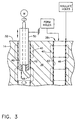
- FIG. 3 and 4 Illustrated schematically in Figures 3 and 4 is a method of making the airfoil 14, or other engine component, for incorporating the striated holes therein in accordance with an exemplary embodiment.
- the airfoil or other component is initially manufactured in any conventional manner such as being cast to shape with the internal channels formed therein.
- the individual discharge holes may be suitably formed in the wall 36 in an initial or first manufacturing step in the form of plain or cylindrical holes 38c.
- the initial plain hole 38c may be formed in any conventional manner such as by drilling, electrical discharge machining, or electrochemical machining in the preferred form of Electro-stream (TM) process as commercially available from the General Electric Company, Cincinnati, Ohio.
- each of the holes 38c is electrically insulated at locations corresponding with the desired lands 42, with the locations of the desired grooves 40 being electrically uninsulated.
- the plain holes 38c may be electrically eroded selectively at the groove locations for forming those grooves 40 without eroding or damaging the portions of the plain holes defining the lands 42.
- the individual plain holes 38c are electrically insulated by coating the entire inner surface of each hole with a suitable electrically insulating coating 46, such as ordinary varnish for example.
- a suitable electrically insulating coating 46 such as ordinary varnish for example.
- the varnish coating may then be selectively stripped at the groove locations for permitting electrical erosion thereof, while retaining the electrical insulation at the land locations.
- the insulating coating 46 is relatively thin, it may be readily stripped away at the groove locations by scratching the coating thereat to expose the underlying wall or substrate material therebelow. Scratching may be effected by rotating a flexible wire 48, such as copper or any suitable metal, for using its tip to scratch away the coating where desired.
- the scratching wire 48 is preferably disposed inside a supporting or protection tube 50, with the tube being disposed inside the plain hole 38c.
- the distal end or tip of the wire 48 extends outwardly from the distal end or tip of the tube so that under rotation of the wire, centrifugal force deflects the wire tip radially outwardly to scratch and remove the coating from the inside of the hole.
- the proximal end of the scratching wire 48 may be rotated using any suitable motor, such as by being mounted in a conventional drill press.
- the protection tube 50 is preferably held stationary and adjusted in position over the length of the hole as desired.
- the scratching wire 48 is preferably axially translated, and oscillated if desired, within the protection tube 50 and inside the hole 38c as the wire rotates for scratching the coating along the axial extent of the groove location to expose the underlying metal substrate.
- the wire and tube are repositioned within each of the plain holes to correspondingly selectively strip the insulating coating from the inside of the holes corresponding with the several locations where the grooves 40 are to be formed.
- the insulating coating 46 is preferably applied over the entire inner surface of the individual holes and selectively removed in the preferred embodiment, the coating may be selectively applied only to the desired land locations in alternate embodiments as practical.
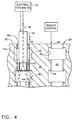
- Figure 4 illustrates the corresponding holes from Figure 3 in which the coating 46 has been selectively stripped at the intended groove locations in the left hole. The groove locations are thusly unprotected whereas the land locations retain their coatings 46 and are protected. The holes may then be selectively eroded at the locations corresponding with the grooves for forming those grooves.
- electrochemical machining in the preferred form of Electro-stream is used for eroding the substrate metal to form the corresponding annular grooves 40.
- Electro-stream process is commercially available from the General Electric Company as indicated above for drilling small and slender holes in workpieces, such as discharge holes in turbine airfoils. This conventional process may be modified in accordance with the present invention for use with the pre-drilled plain holes 38c for selectively eroding the grooves 40.
- a conventional electrochemical machining apparatus 52 configured for Electro-stream operation is used in the preferred embodiment illustrated in Figure 4.
- a hollow glass tube 54 is positioned inside the insulated plain hole 38c, and a thin electrode wire 56 is inserted in the tube.
- a suitable acid electrolyte flows through the tube 54, and the electrode wire 56 is powered with a relatively high voltage.
- the electrolyte attacks and erodes the inner surface of the hole at the exposed, uninsulated groove locations, while the insulated land locations are protected.
- the individual grooves 40 may be electrochemically formed using otherwise conventional equipment.
- the tube 54 and wire 56 are indexed along the length of the hole for forming each of the desired grooves 40 in turn.
- a particular advantage of using electrochemical machining is that erosion of the groove locations additionally undercuts the adjoining lands 42 to form the corresponding cusps 44 thereat. As indicated above, the sharp cusps 44 are preferred for enhancing the tripping effect thereof as opposed to a mere rounded corner in alternate embodiments.
- the remaining insulating coating 46 may be stripped or removed from the lands 42 in any conventional manner, such as by chemical stripping for example.
- the striations defined by the alternating grooves and lands disclosed above are readily formed in relatively small and slender holes with remarkable accuracy and definition. Precise and sharp cusps are readily effected for enhancing coolant tripping.
- the depth of the individual grooves 40 may be relatively shallow without compromising the mechanical strength of the airfoil along its thin trailing edge. And, enhanced cooling is effected without introducing undesirable flow obstruction in the narrow discharge holes which retain their nominal small diameters.
Landscapes
- Engineering & Computer Science (AREA)
- Mechanical Engineering (AREA)
- Physics & Mathematics (AREA)
- Thermal Sciences (AREA)
- General Engineering & Computer Science (AREA)
- Turbine Rotor Nozzle Sealing (AREA)
Abstract
Description
Claims (10)
- A turbine wall (36) having a striated discharge hole (38).
- A wail according to claim 1 wherein said striated hole comprises alternating annular grooves (400 and lands (42).
- A wall according to claim 2 wherein said grooves (40) undercut adjoining lands (42) at corresponding cusps (44).
- A wall according to claim 2 wherein said grooves (40) and lands (42) are coaxially aligned, with a collective length greater than a diameter of said hole.
- A method of making a wall according to any preceding claim comprising:forming a plain hole 38c through said wall 36;electrically insulating said plain hole at locations corresponding with said lands 42; andelectrically eroding said plain hole at locations corresponding with said grooves 40.
- A method according to claim 5 wherein said hole insulating comprises:coating said plain hole (38c) with an electrically insulating coating (46); andstripping said coating at said groove locations for retaining said electrically insulated land locations.
- A method according to claim 6 wherein said coating (46) is stripped at said groove locations by scratching said coating thereat to expose wall material therebelow.
- A turbine airfoil (14) comprising:pressure and suction sides (22, 24) including a wall (36) extending longitudinally from root (26) to tip (28) and chordally between leading and trailing edges (30, 32); anda striated discharge hole (38) extending through said wall and terminating outside said airfoil.
- An airfoil according to claim 8 further comprising:an internal channel (34) for channeling a coolant (20) therethrough; andsaid striated hole (38) includes an inlet (38a) joined with said channel, and an outlet (38b) disposed outside said airfoil for discharging said coolant.
- An airfoil according to claim 9 further comprising a row of said striated holes (38) spaced longitudinally apart between said root and tip along said trailing edge (32), and terminating thereat.
Applications Claiming Priority (2)
| Application Number | Priority Date | Filing Date | Title |
|---|---|---|---|
| US09/432,789 US6254347B1 (en) | 1999-11-03 | 1999-11-03 | Striated cooling hole |
| US432789 | 1999-11-03 |
Publications (2)
| Publication Number | Publication Date |
|---|---|
| EP1098068A2 true EP1098068A2 (en) | 2001-05-09 |
| EP1098068A3 EP1098068A3 (en) | 2003-09-17 |
Family
ID=23717601
Family Applications (1)
| Application Number | Title | Priority Date | Filing Date |
|---|---|---|---|
| EP00309704A Withdrawn EP1098068A3 (en) | 1999-11-03 | 2000-11-02 | Striated cooling hole |
Country Status (5)
| Country | Link |
|---|---|
| US (1) | US6254347B1 (en) |
| EP (1) | EP1098068A3 (en) |
| JP (1) | JP2001173406A (en) |
| BR (1) | BR0005236A (en) |
| SG (1) | SG87908A1 (en) |
Cited By (4)
| Publication number | Priority date | Publication date | Assignee | Title |
|---|---|---|---|---|
| EP1052372A3 (en) * | 1999-05-14 | 2002-11-06 | General Electric Company | Trailing edge cooling passages for gas turbine nozzles with turbulators |
| EP1283327A3 (en) * | 2001-08-09 | 2004-04-21 | General Electric Company | Method for enhancing heat transfer inside a turbulated cooling passage |
| WO2004054748A1 (en) * | 2002-12-18 | 2004-07-01 | Siemens Aktiengesellschaft | Method for the aftertreatment of a through hole of a component |
| EP2848356B1 (en) | 2013-09-11 | 2018-11-14 | General Electric Company | A method for repairing a turbine component wherein damaged material is removed and a plug with improved material properties is inserted and a corresponding repaired component |
Families Citing this family (19)
| Publication number | Priority date | Publication date | Assignee | Title |
|---|---|---|---|---|
| US6539627B2 (en) | 2000-01-19 | 2003-04-01 | General Electric Company | Method of making turbulated cooling holes |
| US6511762B1 (en) * | 2000-11-06 | 2003-01-28 | General Electric Company | Multi-layer thermal barrier coating with transpiration cooling |
| AU2002342500A1 (en) * | 2001-12-10 | 2003-07-09 | Alstom Technology Ltd | Thermally loaded component |
| US6997679B2 (en) * | 2003-12-12 | 2006-02-14 | General Electric Company | Airfoil cooling holes |
| US7901180B2 (en) * | 2007-05-07 | 2011-03-08 | United Technologies Corporation | Enhanced turbine airfoil cooling |
| US8511992B2 (en) * | 2008-01-22 | 2013-08-20 | United Technologies Corporation | Minimization of fouling and fluid losses in turbine airfoils |
| US8128366B2 (en) * | 2008-06-06 | 2012-03-06 | United Technologies Corporation | Counter-vortex film cooling hole design |
| US20090304494A1 (en) * | 2008-06-06 | 2009-12-10 | United Technologies Corporation | Counter-vortex paired film cooling hole design |
| GB201103176D0 (en) * | 2011-02-24 | 2011-04-06 | Rolls Royce Plc | Endwall component for a turbine stage of a gas turbine engine |
| CH705185A1 (en) * | 2011-06-29 | 2012-12-31 | Alstom Technology Ltd | Blade for a gas turbine and processes for manufacturing such a blade. |
| US9133819B2 (en) | 2011-07-18 | 2015-09-15 | Kohana Technologies Inc. | Turbine blades and systems with forward blowing slots |
| GB2498551B (en) * | 2012-01-20 | 2015-07-08 | Rolls Royce Plc | Aerofoil cooling |
| DE102012110016A1 (en) | 2012-10-19 | 2014-04-24 | Bernhard Wietrzynski | Method for producing recess portion in bone for growth of tissue, used in medical field, involves performing electro-chemical removal of material while moving electrode at movement portion along movement direction to larger distance |
| US10378362B2 (en) | 2013-03-15 | 2019-08-13 | United Technologies Corporation | Gas turbine engine component cooling channels |
| US20140360155A1 (en) * | 2013-06-07 | 2014-12-11 | General Electric Company | Microchannel systems and methods for cooling turbine components of a gas turbine engine |
| US10533749B2 (en) * | 2015-10-27 | 2020-01-14 | Pratt & Whitney Cananda Corp. | Effusion cooling holes |
| US10871075B2 (en) | 2015-10-27 | 2020-12-22 | Pratt & Whitney Canada Corp. | Cooling passages in a turbine component |
| US10989070B2 (en) * | 2018-05-31 | 2021-04-27 | General Electric Company | Shroud for gas turbine engine |
| US11885230B2 (en) * | 2021-03-16 | 2024-01-30 | Doosan Heavy Industries & Construction Co. Ltd. | Airfoil with internal crossover passages and pin array |
Family Cites Families (9)
| Publication number | Priority date | Publication date | Assignee | Title |
|---|---|---|---|---|
| NL93457C (en) * | 1955-12-30 | |||
| GB1381481A (en) * | 1971-08-26 | 1975-01-22 | Rolls Royce | Aerofoil-shaped blades |
| US4407632A (en) * | 1981-06-26 | 1983-10-04 | United Technologies Corporation | Airfoil pedestaled trailing edge region cooling configuration |
| US4669957A (en) * | 1985-12-23 | 1987-06-02 | United Technologies Corporation | Film coolant passage with swirl diffuser |
| US4738588A (en) * | 1985-12-23 | 1988-04-19 | Field Robert E | Film cooling passages with step diffuser |
| JPH06179125A (en) * | 1992-12-16 | 1994-06-28 | Mitsubishi Heavy Ind Ltd | Special electrode for machining inner surface deformed hole |
| US5306401A (en) * | 1993-03-15 | 1994-04-26 | Fierkens Richard H J | Method for drilling cooling holes in turbine blades |
| US5738493A (en) * | 1997-01-03 | 1998-04-14 | General Electric Company | Turbulator configuration for cooling passages of an airfoil in a gas turbine engine |
| US5752801A (en) * | 1997-02-20 | 1998-05-19 | Westinghouse Electric Corporation | Apparatus for cooling a gas turbine airfoil and method of making same |
-
1999
- 1999-11-03 US US09/432,789 patent/US6254347B1/en not_active Expired - Fee Related
-
2000
- 2000-10-31 SG SG200006271A patent/SG87908A1/en unknown
- 2000-11-02 JP JP2000335301A patent/JP2001173406A/en not_active Withdrawn
- 2000-11-02 EP EP00309704A patent/EP1098068A3/en not_active Withdrawn
- 2000-11-06 BR BR0005236-1A patent/BR0005236A/en not_active IP Right Cessation
Cited By (4)
| Publication number | Priority date | Publication date | Assignee | Title |
|---|---|---|---|---|
| EP1052372A3 (en) * | 1999-05-14 | 2002-11-06 | General Electric Company | Trailing edge cooling passages for gas turbine nozzles with turbulators |
| EP1283327A3 (en) * | 2001-08-09 | 2004-04-21 | General Electric Company | Method for enhancing heat transfer inside a turbulated cooling passage |
| WO2004054748A1 (en) * | 2002-12-18 | 2004-07-01 | Siemens Aktiengesellschaft | Method for the aftertreatment of a through hole of a component |
| EP2848356B1 (en) | 2013-09-11 | 2018-11-14 | General Electric Company | A method for repairing a turbine component wherein damaged material is removed and a plug with improved material properties is inserted and a corresponding repaired component |
Also Published As
| Publication number | Publication date |
|---|---|
| BR0005236A (en) | 2001-07-24 |
| JP2001173406A (en) | 2001-06-26 |
| EP1098068A3 (en) | 2003-09-17 |
| SG87908A1 (en) | 2002-04-16 |
| US6254347B1 (en) | 2001-07-03 |
Similar Documents
| Publication | Publication Date | Title |
|---|---|---|
| US6254347B1 (en) | Striated cooling hole | |
| EP1283327B1 (en) | Method for enhancing heat transfer inside a turbulated cooling passage | |
| US6554571B1 (en) | Curved turbulator configuration for airfoils and method and electrode for machining the configuration | |
| EP1201343B1 (en) | Turbine bucket with turbulated cooling passage and electrode for electochemical machining. | |
| EP1057970B1 (en) | Impingement cooled airfoil tip | |
| CA2480989C (en) | Teardrop film cooled blade | |
| US7527474B1 (en) | Turbine airfoil with mini-serpentine cooling passages | |
| CA2495926A1 (en) | Thermal shield turbine airfoil | |
| EP1793087B1 (en) | Blunt tip turbine blade | |
| US6955522B2 (en) | Method and apparatus for cooling an airfoil | |
| CN1327997C (en) | Device and method for renewing cooling path in turbine wing surface | |
| US6135715A (en) | Tip insulated airfoil | |
| US7118342B2 (en) | Fluted tip turbine blade | |
| EP2527597A2 (en) | Turbine blade with curved film cooling passages | |
| WO2014031189A1 (en) | Asymmetrically shaped trailing edge cooling holes | |
| US11415000B2 (en) | Turbine airfoil with trailing edge features and casting core | |
| EP1764477A1 (en) | Fluted tip turbine blade | |
| JP2015013362A (en) | Method for fabricating microchannels in fluid cooling components | |
| JP2021102929A (en) | Turbine blade, method for manufacturing turbine blade, and gas turbine |
Legal Events
| Date | Code | Title | Description |
|---|---|---|---|
| PUAI | Public reference made under article 153(3) epc to a published international application that has entered the european phase |
Free format text: ORIGINAL CODE: 0009012 |
|
| AK | Designated contracting states |
Kind code of ref document: A2 Designated state(s): AT BE CH CY DE DK ES FI FR GB GR IE IT LI LU MC NL PT SE TR |
|
| AX | Request for extension of the european patent |
Free format text: AL;LT;LV;MK;RO;SI |
|
| PUAL | Search report despatched |
Free format text: ORIGINAL CODE: 0009013 |
|
| AK | Designated contracting states |
Kind code of ref document: A3 Designated state(s): AT BE CH CY DE DK ES FI FR GB GR IE IT LI LU MC NL PT SE TR |
|
| AX | Request for extension of the european patent |
Extension state: AL LT LV MK RO SI |
|
| RIC1 | Information provided on ipc code assigned before grant |
Ipc: 7B 23H 9/16 B Ipc: 7B 23H 9/14 B Ipc: 7B 23H 3/00 B Ipc: 7F 01D 5/18 A |
|
| AKX | Designation fees paid | ||
| REG | Reference to a national code |
Ref country code: DE Ref legal event code: 8566 |
|
| STAA | Information on the status of an ep patent application or granted ep patent |
Free format text: STATUS: THE APPLICATION IS DEEMED TO BE WITHDRAWN |
|
| 18D | Application deemed to be withdrawn |
Effective date: 20040318 |