EP1097855A2 - Steering device for vehicle - Google Patents
Steering device for vehicle Download PDFInfo
- Publication number
- EP1097855A2 EP1097855A2 EP00122793A EP00122793A EP1097855A2 EP 1097855 A2 EP1097855 A2 EP 1097855A2 EP 00122793 A EP00122793 A EP 00122793A EP 00122793 A EP00122793 A EP 00122793A EP 1097855 A2 EP1097855 A2 EP 1097855A2
- Authority
- EP
- European Patent Office
- Prior art keywords
- vehicle
- steering angle
- target
- index value
- operating
- Prior art date
- Legal status (The legal status is an assumption and is not a legal conclusion. Google has not performed a legal analysis and makes no representation as to the accuracy of the status listed.)
- Granted
Links
Images


Classifications
-
- B—PERFORMING OPERATIONS; TRANSPORTING
- B62—LAND VEHICLES FOR TRAVELLING OTHERWISE THAN ON RAILS
- B62D—MOTOR VEHICLES; TRAILERS
- B62D6/00—Arrangements for automatically controlling steering depending on driving conditions sensed and responded to, e.g. control circuits
- B62D6/008—Control of feed-back to the steering input member, e.g. simulating road feel in steer-by-wire applications
-
- B—PERFORMING OPERATIONS; TRANSPORTING
- B62—LAND VEHICLES FOR TRAVELLING OTHERWISE THAN ON RAILS
- B62D—MOTOR VEHICLES; TRAILERS
- B62D5/00—Power-assisted or power-driven steering
- B62D5/001—Mechanical components or aspects of steer-by-wire systems, not otherwise provided for in this maingroup
- B62D5/005—Mechanical components or aspects of steer-by-wire systems, not otherwise provided for in this maingroup means for generating torque on steering wheel or input member, e.g. feedback
- B62D5/006—Mechanical components or aspects of steer-by-wire systems, not otherwise provided for in this maingroup means for generating torque on steering wheel or input member, e.g. feedback power actuated
-
- B—PERFORMING OPERATIONS; TRANSPORTING
- B62—LAND VEHICLES FOR TRAVELLING OTHERWISE THAN ON RAILS
- B62D—MOTOR VEHICLES; TRAILERS
- B62D6/00—Arrangements for automatically controlling steering depending on driving conditions sensed and responded to, e.g. control circuits
- B62D6/002—Arrangements for automatically controlling steering depending on driving conditions sensed and responded to, e.g. control circuits computing target steering angles for front or rear wheels
- B62D6/003—Arrangements for automatically controlling steering depending on driving conditions sensed and responded to, e.g. control circuits computing target steering angles for front or rear wheels in order to control vehicle yaw movement, i.e. around a vertical axis
Definitions
- the present invention relates to a steering device for a vehicle to which a so-called 'steer by electrical wire' system is applied.
- a steering actuator In a steering device for a vehicle incorporating a 'steer by electrical wire' system, the movement of a steering actuator is transmitted to the wheels of the vehicle in such a manner that the steering angle thereof changes in accordance with the degree of operation of a rotatable operating member, which is modelled on a steering wheel, without the operating member being coupled mechanically to the wheels of the vehicle.
- a target steering angle corresponding to the amount of operation of the operating member is determined, and the steering actuator is controlled in such a manner that steering angle corresponds to the target steering angle.
- a method has also been proposed whereby a target value for the yaw rate corresponding to the change in the behaviour of the vehicle due to the change in steering angle is determined in accordance with the amount of operation of the operating member, a target steering angle is determined in such a manner that the detected actual yaw rate of the vehicle assumes the target yaw rate, and the steering angle actuator is controlled in such a manner that the steering angle corresponds to the target steering angle.
- a steering actuator for generating a reactive torque acting on the operating member is provided, whereby a reactive torque corresponding to the amount of operation of the operating member is applied to the operating member.
- a method may be conceived whereby the steering actuator is controlled by determining a target steering angle according to the amount of operation of the operating member, in the low vehicle speed range, whilst the steering actuator is controlled by determining a target steering angle according to the actual yaw rate of the vehicle, in the medium and high vehicle speed range; but at the boundary between the low vehicle speed range and the medium to high vehicle speed range, the amount of control of the steering actuator changes suddenly, and hence the behaviour of the vehicle becomes unstable.
- the steering device for a vehicle is characterized in that it comprises: an operating member; a steering actuator driven in accordance with operation of the operating member, means for transmitting the movement of the steering actuator to the wheels of a vehicle in such a manner that the steering angle changes in accordance with the movement, without the operating member being coupled mechanically to the vehicle wheels; means for determining a behaviour index value corresponding to change in the behaviour of the vehicle; means for detecting the amount of operation of the operating member; means for calculating a target behaviour index value corresponding to the detected amount of operation, on the basis of a stored relationship between the amount of operation and the target behaviour index value; means for calculating a steering angle set value corresponding to the calculated target behaviour index value, on the basis of a stored relationship between the target behaviour index value and the steering angle set value; means for calculating a steering angle correction value corresponding to the differential between the target behaviour index value and the aforementioned determined behaviour index value, on the basis of a stored relationship between this differential and the steering angle correction value; and means for controlling the steering actuator
- the steering actuator is controlled in such a manner that it corresponds to a target steering angle being the sum of a steering angle set value and a steering angle correction value;
- the steering angle set value corresponds to a target behaviour index value which relates to the amount of operation of the operating member;
- the steering angle correction value corresponds to the differential between this target behaviour index value and a determined behaviour index value. Since the steering angle set value corresponds to a feed-forward element in the target steering angle and the steering angle correction value corresponds to a feed-back element thereof, integrated control combining feed-forward control and feed-back control is performed. Thereby, it is possible to achieve optimisation of vehicle behaviour, by causing the steering angle of the vehicle to change in accordance with the amount of operation of the operating member, and also by controlling the steering actuator in accordance with change in the behaviour of the vehicle.
- the yaw rate or lateral acceleration of the vehicle can be employed as the aforementioned behaviour index value.
- the stored relationship between the target behaviour index value and the steering angle set value corresponds to the inverse of the transfer function of the behaviour index value with respect to the steering angle.
- the relationship between the target behaviour index value and the steering angle set value corresponds to the inverse of the transfer function corresponding to the transient response characteristics of the vehicle behaviour with respect to change in the steering angle, it is possible to improve the responsiveness and stability of the transient response by means of feed-forward control.
- the stored relationship between the differential of the target behaviour index value and the behaviour index value, and the steering angle correction value is the inverse of the transfer function of the behaviour index value with respect to the steering angle.
- the relationship between the steering angle correction value and the differential between the target behaviour index value and the behaviour index value corresponds to the inverse of the transfer function relating to transient response characteristics of the vehicle behaviour with respect to change in the steering angle, the responsiveness and stability of the transient response are improved by feed-back control, and hence the steering feel and the stability of the vehicle behaviour are improved.
- the aforementioned target behaviour index value is calculated in such a manner that the ratio of the yaw rate or lateral acceleration of the vehicle with respect to the amount of operation of the operating member is uniform, irrespective of the vehicle speed.
- the operating member is rotationally operated; the amount of operation of the operating member is taken as the operating torque imparted to the operating member by the driver of the vehicle; and an operating actuator for generating a reactive torque acting on the operating member is provided; there also being provided: means for detecting the rotational operating angle of the operating member due to the action of the differential between the detecting operating torque and the generated reactive torque; means for calculating a target reactive torque corresponding to the detected rotational operating angle, on the basis of a stored relationship between the rotational operating angle and the target reactive torque; and means for controlling the operating actuator in such a manner that the reactive torque corresponds to the target reactive torque.
- the operating torque imparted to the operating member by the driver is employed as the amount of operation of the operating member.
- the operating member is rotationally operated; the amount of operation of the operating member is taken as the operating torque imparted to the operating member by the driver of the vehicle; and an operating actuator for generating a reactive torque acting on the operating member is provided; there being further provided: means for detecting the rotational operating angle of the operating member due to the action of the differential between the detecting operating torque and the generated reactive torque; means for calculating a reactive torque set value corresponding to the detected rotational operating angle, on the basis of a stored relationship between the rotational operating angle and the reactive torque set value; means for calculating a behaviour-related rotational operating angle for the operating member corresponding to the determined behaviour index value, on the basis of a stored relationship between the behaviour index value and the behaviour-related rotational operating angle; means for calculating a reactive torque correction value corresponding to the differential between the detected rotational operating angle and the calculated behaviour-related rotational operating angle, on the basis of a stored relationship between this differential and the reactive torque correction value; and means for controlling the operating actuator in such a manner that the reactive
- the operating torque imparted to the operating member by the driver is employed as the amount of operation of the operating member.
- a reactive torque correction value is determined according to the differential between a behaviour-related rotational operating angle corresponding to the actual behaviour index value of the vehicle and a detected rotational operating angle, and a target reactive torque being obtained by summing this reactive torque correction value with a reactive torque set value corresponding to the rotational operating angle, and therefore the reactive torque reflects changes in the actual behaviour of the vehicle.
- the attitude of the vehicle can be corrected more readily in response to sudden steering actions, hence improving driving stability, and the driving characteristics of the vehicle are made to correspond to the operating torque imparted by the driver, the vehicle being steered in accordance with this operating torque.
- the reactive torque correction value is taken as zero, at speeds lower than a previously set vehicle speed.
- the operating actuator can be controlled such that the reactive torque corresponds to the reactive torque set value corresponding to the rotational operating angle.
- the operating actuator can be controlled such that the reactive torque coincides with target reactive torque which is the sum of the reactive torque set value and the reactive torque correction value. Therefore, the control amount of the operating actuator will not change abruptly at the border between the low vehicle speed range and the medium to high speed range, and the vehicle can be operated in accordance with the driver's operating torque by controlling the operating actuator in accordance with the change in behaviour of the vehicle.
- the target steering angle corresponding to the detected amount of operation is calculated based on a stored relationship between the amount of operation and the target steering angle, and the steering angle correction value is taken as zero.
- the target steering angle is determined in accordance with the operating torque.
- the target steering angle is taken as the sum of a steering angle set value corresponding to the target behaviour index value and a steering angle correction value corresponding to the differential between the target behaviour index value and the actual behaviour index value, and the steering actuator is controlled in such a manner that the steering angle coincides with the target steering angle. Therefore, the amount of control applied to the steering actuator at the boundary between the low speed range and the medium to high speed range is equalized, thereby preventing the vehicle behaviour from becoming unstable.
- the relationship between the target behaviour index value and the steering angle set value corresponds to the inverse of the transfer function relating to transient response characteristics of the vehicle behaviour with respect to change in steering angle, the responsiveness and stability of the transient response are improved by feed-forward control, and hence the steering feel and the stability of the vehicle behaviour are improved.
- K1 and K2 are taken as functions of the vehicle speed, in such a manner that the transient response of the vehicle behaviour with respect to change in the steering angle corresponds to a previously determined uniform response, irrespective of the vehicle speed.
- the transient response of the vehicle behaviour with respect to change in the steering angle is made to correspond to a model response, thereby improving said transient response characteristics.
- a steering device for a vehicle whereby it is possible to cause the steering angle of a vehicle to change in accordance with the amount of operation of an operating member, without causing the vehicle behaviour to become unstable in the transition from a low speed range to a medium to high speed range, and hence vehicle behaviour can be optimized, operability can be improved, the attitude of the vehicle can be corrected more readily even in the case of sudden steering actions at high vehicle speeds, thereby improving driving stability, the vehicle can be steered according to operating torque, and moreover, the responsiveness and stability of the transient response of the vehicle behaviour with respect to changes in the steering angle can be improved, thereby improving the steering feel and stability of vehicle behaviour.
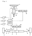
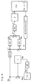
- the steering device for a vehicle illustrated in Fig. 1 comprises: an operating member 1 modelled on a steering wheel; a steering actuator 2 which is driven in accordance with rotational operation of the operating member 1; and a steering gear 3 which transmits the movement of the steering actuator 2 to the front right and left steerable wheels 4 of the vehicle, in such a manner that the steering angle changes in accordance with the movement of the steering actuator 2, without the operating member 1 being coupled mechanically to the vehicle wheels 4.
- the steering actuator 2 can be constituted by electric motors, such as commonly known brushless motors, or the like.
- the steering gear 3 comprises a movement converting mechanism for converting the rotational movement of the output shaft of the steering actuator 2 to linear movement of a steering rod 7.
- the movement of this steering rod 7 is further transmitted via tie rods 8 and knuckle arms 9 to the vehicle wheels 4, thereby changing the tow angle of the vehicle wheels 4.
- a commonly used device can be used for the steering gear 3, the constitution of which is not limited, provided that it transmits the movement of the steering actuator 2 to the vehicle wheels 4 in such a manner that the steering angle changes.
- the wheel alignment is set in such a manner that, in a state where the steering actuator 2 is not being driven, the vehicle wheels 4 are able to return to a forward steering position by means of a self-aligning torque.
- the operating member 1 is coupled to a rotating shaft 10 supported rotatably by the main body of the vehicle.
- An operating actuator 19 for generating a reactive torque acting on the operating member 1 is also provided.
- This operating actuator 19 can be constituted by an electric motor, such as a brushless motor, or the like, having an output shaft that is integrated with the rotating shaft 10.
- An elastic member 30 is provided applying an elastic force to the operating member 1 in a direction causing the member 1 to return to a forward steering position.
- This elastic member 30 can be constituted by means of a spring applying elastic force to the rotating shaft 10, for example.
- the operating member 1 is caused to revert to the forward steering position by means of the elastic force of the elastic member 30.
- An angle sensor 11 is provided for detecting the angle of rotational operation of the operating member 1 by means of the angle of rotation of the rotating shaft 10.
- a torque sensor 12 is provided for detecting the operating torque imparted by the vehicle driver on the operating member 1 by means of the torque transmitted by the rotating shaft 10.
- a steering angle sensor 13 for detecting the steering angle of the vehicle is constituted by means of a potentiometer which detects the amount of operation of the steering rod 7 corresponding to the steering angle.
- a speed sensor 14 for detecting the vehicle speed is provided.
- a lateral acceleration sensor 15 for detecting the lateral acceleration of the vehicle is provided.
- a yaw rate sensor 16 for detecting the yaw rate of the vehicle is provided.
- the aforementioned angle sensor 11, torque sensor 12, steering angle sensor 13, speed sensor 14, lateral acceleration sensor 15 and yaw rate sensor 16 are connected to a control device 20 constituted by a computer.
- This control device 20 controls the steering actuator 2 and operating actuator 19 via driving circuits 22, 23.
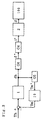
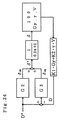
- Fig. 2 shows a control block diagram of the control device 20 according to the first embodiment, in a case where the vehicle speed is equal to or greater than a previously determined vehicle speed.
- the angle of rotational operation as detected by the aforementioned angle sensor 11 is taken as the amount of operation of the operating member 1.
- the lateral acceleration Gy is detected by the aforementioned lateral acceleration sensor 15, the yaw rate ⁇ by the yaw rate sensor 16, and the vehicle speed V by the speed sensor 14, respectively, the aforementioned relationship being stored in the control device 20 and the behaviour index value D being calculated by the control device 20 from the respective detected value and the stored expression.
- the control device 20 calculates the target behaviour index value D* corresponding to the rotational operating angle ⁇ h of the operating member 1 as detected by the angle sensor 11, on the basis of the transfer function G1 which represents the relationship between the rotational angle of operation ⁇ h and the target behaviour index value D*.
- This transfer function G1 is previously determined and stored in the control device 20.
- the controller of D* with respect to ⁇ h is a proportional control element, the proportional gain of which is proportional to the vehicle speed V.
- the target behaviour index value D* is calculated in such a manner that the ratio of the yaw rate ⁇ of the vehicle with respect to the rotational operating angle ⁇ h of the operating member 1 is uniform, irrespective of the vehicle speed.
- the proportional constant K D1 is adjusted in such a manner that optimum control is provided, for example, it is set to 4/3.
- the target behaviour index value D* may be calculated in such a manner that the ratio of the lateral acceleration Gy of the vehicle with respect to the rotational operating angle ⁇ h of the operating member 1 is uniform, irrespective of the vehicle speed.
- the control device 20 calculates the steering angle set value ⁇ FF corresponding to the target behaviour index value D* derived above, on the basis of the transfer function G2 which represents the relationship between the target behaviour index value D* and the steering angle set value ⁇ FF .
- This transfer function G2 is previously determined and stored in the control device 20.
- the gain G D (v) is determined by the following expression, where SF is the stability factor and L is the vehicle wheelbase.
- G D (v) V 2 / ⁇ (1+SF ⁇ V 2 )L ⁇
- the control device 20 calculates the differential (D* - D) between the calculated target behaviour index value D* and the behaviour index value D determined on the basis of the detected values for lateral acceleration Gy, yaw rate ⁇ , and vehicle speed V, and it further calculates the steering angle correction value ⁇ FB corresponding to the differential (D* - D) on the basis of the transfer function G3 representing relationship between the differential (D* - D) and the steering angle correction angle ⁇ FB .
- the transfer function G3 is previously determined and stored in the control device 20.
- the transfer function G3 is taken as (Kp + Ki/s)/G D (v) , where Kp is the proportional gain, Ki is the integral gain, and s is the Laplace operator, in such a manner that PI (Proportional Integral) control is achieved.
- PI Proportional Integral
- the control device 20 calculates the target drive current i* for the steering actuator 2 corresponding to the calculated target steering angle ⁇ *, on the basis of the transfer function G4 which represents the relationship between the target steering angle ⁇ * and the target drive current i*.
- This transfer function G4 is previously determined and stored in the control device 20.
- the steering actuator 2 is driven in accordance with the target drive current i*. Thereby, the steering actuator 2 is controlled by the control device 20 in such a manner that the steering angle ⁇ corresponds to the target steering angle ⁇ *.
- the control device 20 calculates the target reactive torque Tm* corresponding to the rotational operating angle oh of the operating member 1 as detected by the angle sensor 11, on the basis of a transfer function G5 which represents the relationship between the rotational operating angle ⁇ h and the target reactive torque Tm*.
- This transfer function G5 is previously determined and stored in the control device 20.
- the operating actuator 19 is controlled by the control device 20 in such a manner that the reactive torque Tm corresponds to the target reactive torque Tm*.
- the controller of the target reactive torque Tm* corresponding to the rotational operating angle Oh is a proportional control element, and the proportional gain thereof Kt is constant, irrespective of the vehicle speed.
- the absolute value of the target reactive torque Tm* may be set in such a manner that it does not exceed a predetermined upper limit, for example, 10 N ⁇ m, in such a manner that reactive torque is never applied to an excessive degree.
- Fig. 3 shows a control block diagram of a control device 20 according to the first embodiment, in a case where the vehicle speed is less than the aforementioned previously set vehicle speed Va.
- G6 is the transfer function of the controller of ⁇ * corresponding to ⁇ h, and the steering angle correction value ⁇ FB is set to zero, apart from which, the situation is similar to that in Fig. 2.
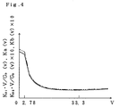
- the previously set vehicle speed Va should be determined in such a manner that at speeds exceeding this vehicle speed Va, the target steering angle ⁇ * can be set appropriately on the basis of the calculated behaviour index value D, for example, Va is set to 2.78 m/s.
- the control device 20 calculates the target steering angle ⁇ * corresponding to the rotational operating angle ⁇ h of the operating member 1 as detected by the angle sensor 11, on the basis of a transfer function G6 which represents the relationship between the rotational operating angle ⁇ h and the target steering angle ⁇ *.
- This transfer function G6 is previously determined and stored in the control device 20.
- the solid lines in Fig. 4 indicate the relationship between K D1 ⁇ V/G D (v) and the vehicle speed V when the vehicle speed V is equal to or greater than the aforementioned set vehicle speed Va, and also indicate the relationship between Ka(v) and the vehicle speed V when the vehicle speed is less than the aforementioned set vehicle speed Va.
- K D1 4/3
- SF 0.0011 s 2 /m 2
- L 2.512 m
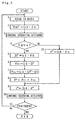
- the target reactive torque Tm* corresponding to the detected rotational operating angle oh is calculated (step 2), and the operating actuator 19 is controlled in such a manner that the reactive torque Tm corresponds to the target reactive torque Tm* (step 3).
- step 4 it is determined whether or not the vehicle speed V is equal to or greater than a set value Va (step 4).
- a target behaviour index value D* is calculated in accordance with the detected rotational operating angle ⁇ h (step 5)
- a steering angle set angle ⁇ FF corresponding to the calculated target behaviour index value D* is calculated (step 6)
- the differential (D* - D) between the calculated target behaviour index value D* and a behaviour index value D determined on the basis of the detected values for the lateral acceleration Gy, yaw rate ⁇ and vehicle speed V is calculated
- a steering angle correction value ⁇ FB corresponding to this differential (D* - D) is calculated (step 7)
- a target steering angle ⁇ * is calculated as the sum of the steering angle set value ⁇ FF and the steering angle correction value ⁇ FB (step 8).
- the target drive current i* for the steering actuator 2 corresponding to the determined target steering angle ⁇ * is calculated (step 9), and by driving the steering actuator 2 in accordance with this target drive current i*, the steering actuator 2 is controlled in such a manner that the steering angle ⁇ corresponds to the target steering angle ⁇ * (step 10).
- step 11 it is determined whether or not to finish the control procedure, on the basis of whether or not the ignition switch of the vehicle is on, for example (step 11), and if it is not to be finished, the sequence returns to step 1.
- a target steering angle ⁇ * is calculated in accordance with the detected rotational operating angle ⁇ h (step 12), whereupon, at step 9, the target drive current i* of the steering actuator 2 corresponding to the target steering angle ⁇ * is calculated.
- the steering actuator 2 is controlled in such a manner that it corresponds to the target steering angle ⁇ * being the sum of the steering angle set value ⁇ FF , which corresponds to the target behaviour index value D* relating to the rotational operating angle ⁇ h, and the steering angle correction value ⁇ FB , which corresponds to the difference (D* - D) between the target behaviour index value D* and the determined behaviour index value D.
- the steering angle set value ⁇ FF corresponds to a feed-forward element
- the steering angle correction value ⁇ FB corresponds to a feed-back element in the target steering angle ⁇ *
- integrated control combining feed-forward control and feed-back control is performed.
- the steering angle ⁇ of the vehicle is caused to change in accordance with the amount of operation of the operating member 1, whilst at the same time, the behaviour of the vehicle is optimised by controlling the steering actuator 2 in accordance with change in the behaviour of the vehicle.
- operating characteristics can be improved by setting the ratio of the vehicle yaw rate ⁇ with respect to the amount of operation of the operating member 1 to a uniform value, regardless of the vehicle speed, when calculating the target behaviour index value D*.
- the target steering angle ⁇ * is determined in accordance with the rotational operating angle ⁇ h
- the target steering angle ⁇ * is derived as the sum of the steering angle set angle ⁇ FF corresponding to the target behaviour index value D* and the steering angle correction value ⁇ FB corresponding to the differential (D* - D) between this target behaviour index value D* and the actual behaviour index value D, and the steering actuator 2 is controlled in such a manner that the steering angle matches this target steering angle ⁇ *. Therefore, since the amount of control applied to the steering actuator 2 is equalized at the boundary between the low speed range and the medium to high speed range (this boundary being at set vehicle speed Va), it is possible to prevent the vehicle behaviour from becoming unstable.
- Fig. 6 shows a control block diagram of a control device 20 according to the second embodiment, in a case where the vehicle speed is equal to or greater than a previously set vehicle speed Va.
- the operating torque Th imparted by the vehicle driver on the operating member 1 is taken as the amount of operation of the operating member 1.
- G11 is a transfer function of the controller of D* with respect to Th, apart from which the situation is the same as that illustrated in Fig. 2.
- the control device 20 calculates a target behaviour index value D* corresponding to the operating torque Th of the operating member 1 as detected by the torque sensor 12, on the basis of the transfer function G11 which represents the relationship between the operating torque Th and the target behaviour index value D*.
- This transfer function G11 is previously determined and stored in the control device 20.
- the controller of D* with respect to Th is a proportional control element, the proportional gain of which is set as being directly proportional to the vehicle speed V.
- K D2 is a proportional constant.
- the target behaviour index value D* is calculated in such a manner that the ratio of the vehicle yaw rate ⁇ with respect to the operating torque Th of the operating member 1 is uniform, regardless of the vehicle speed.
- the proportional constant K D2 is adjusted in such a manner that optimum control is provided, being set, for example, to a value of ⁇ /22.5.
- the target behaviour index value D* may also be calculated in such a manner that the ratio of the lateral acceleration Gy of the vehicle with respect to the operating torque Th of the operating member 1 is uniform irrespective of the vehicle speed, by setting the transfer function G11 constant.
- Fig. 7 shows a control block diagram of a control device 20 according to the second embodiment of the invention, in a case where the vehicle speed is less than the aforementioned predetermined vehicle speed Va.
- G12 is the transfer function of the controller of ⁇ * with respect to Th, and the steering angle correction angle ⁇ FB is taken as 0, apart from which the situation is similar to that depicted in Fig. 6.
- the control device 20 calculates a target steering angle ⁇ * corresponding to the operating torque Th of the operating member 1 as detected by the torque sensor 12, on the basis of the transfer function G12 which represents the relationship between the operating torque Th and the target steering angle ⁇ *.
- This transfer function G12 is previously determined and stored in the control device 20.
- the double-dotted lines in Fig. 4 indicate the indicate the relationship between K D2 ⁇ V/G D (v) ⁇ 10 and the vehicle speed V, when the vehicle speed V is equal to or greater than the aforementioned set vehicle speed Va, and the relationship between Kb(v) ⁇ 10 and the vehicle speed V when the vehicle speed is less than the aforementioned set vehicle speed Va.
- K D2 ⁇ /22.5
- SF 0.0011 s 2 /m 2
- L 2.512 m.
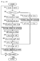
- control procedure implemented by the control device 20 according to the second embodiment described above is now explained with reference to the flowchart in Fig. 8. Firstly, the detection data is read in from the respective sensors (step 101).
- the target reactive torque Tm* corresponding to the detected rotational operating angle oh is calculated (step 102), and the operating actuator 19 is controlled in such a manner that the reactive torque Tm corresponds to the target reactive torque Tm* (step 103).
- step 104 it is determined whether or not the vehicle speed V is equal to or greater than a set value Va (step 104).
- a target behaviour index value D* is calculated in accordance with the detected operating torque Th (step 105)
- a steering angle set value ⁇ FF corresponding to the calculated target behaviour index value D* is calculated (step 106)
- the differential (D* - D) between the calculated target behaviour index value D* and a behaviour index value D determined on the basis of the detected values for the lateral acceleration Gy, yaw rate ⁇ and vehicle speed V is calculated
- a steering angle correction value ⁇ FB corresponding to this differential (D* - D) is calculated (step 107)
- a target steering angle ⁇ * is calculated as the sum of the steering angle set value ⁇ FF and the steering angle correction value ⁇ FF (step 108).
- a target drive current i* for the steering actuator 2 corresponding to the calculated target steering angle ⁇ * is calculated (step 109), and by driving the steering actuator 2 in accordance with this target drive current i*, the steering actuator 2 is controlled in such a manner that the steering angle ⁇ corresponds to the target steering angle ⁇ * (step 110).
- step 111 it is determined whether or not to finish the control procedure, on the basis of whether or not the ignition switch of the vehicle is on, for example (step 111), and if it is not to be finished, the sequence returns to step 101.
- a target steering angle ⁇ * is calculated in accordance with the detected operating torque Th (step 112), whereupon, at step 109, the target drive current i* of the steering actuator 2 corresponding to the target steering angle ⁇ * is calculated.
- this embodiment is similar to the first embodiment.
- the operating torque imparted by the driver on the operating member 1 is employed as the amount of operation of the operating member 1.
- the delay from the time that the driver imparts an operating torque to the time that the steering angle changes is improved, thereby allowing the attitude of the vehicle to be corrected readily even in the case of sudden steering actions in the high speed range, and hence improving driving stability.
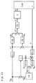
- Fig. 9 is a control block diagram of a control device 20 according to the third embodiment of the invention, in a case where the vehicle speed is equal to or greater than a previously set vehicle speed Va.
- the operating torque Th imparted by the vehicle driver on the operating member 1 is taken as the amount of operation of the operating member 1.
- T FF is a reactive torque set value
- ⁇ D is a behaviour-related rotational operating angle
- T FB is a reactive torque correction value
- G13 is the transfer function of the controller of T FF with respect to ⁇ h
- G14 is the transfer function of the controller of ⁇ D with respect to D
- G15 is the transfer function of the controller of T FB with respect to the differential between ⁇ h and ⁇ D .
- the control device 20 calculates a reactive torque set value T FF corresponding to the rotational operating angle ⁇ h of the operating member 1 as detected by the angle sensor 11, on the basis of the transfer function G13 which represents the relationship between the rotational operating angle ⁇ h and the reactive torque set value T FF .
- the transfer function G13 is previously determined and stored in the control device 20.
- the controller of the reactive torque set value T FF with respect to the rotational operating angle ⁇ h is taken as a proportional control element, of which the proportional gain Kt is taken as constant, irrespective of the vehicle speed.
- T FF Kt ⁇ ⁇ h .
- the absolute value of the reactive torque set value T FF is not permitted to exceed a previously determined upper limit, for example, 10 N ⁇ m, in such a manner that reactive torque is never applied to an excessive degree.
- the control device 20 calculates a behaviour-related rotational operating angle ⁇ D , which corresponds to a behaviour index value D derived from the detected values for lateral acceleration Gy, yaw rate ⁇ , and vehicle speed V, on the basis of the transfer function G14 which represents the stored relationship between the behaviour index value D and the behaviour-related rotational operating angle ⁇ D .
- This transfer function G14 is previously determined and stored in the control device 20.
- the controller of the behaviour-related rotational operating angle ⁇ D is taken as a proportional control element, of which the proportional gain is set as a factor K ⁇ (v) of the vehicle speed V.
- ⁇ D K ⁇ (v) ⁇ D .
- K ⁇ (v) 1/K D2 ⁇ Kt ⁇ V
- K ⁇ (v) 3/4V
- the control device 20 calculates the differential ( ⁇ h - ⁇ D ) between the detected rotational operating angle ⁇ h and the calculated behaviour-related rotational operating angle ⁇ D , and further calculates a reactive torque correction value T FB corresponding to this differential ( ⁇ h - ⁇ D ), on the basis of the transfer function G15 which represents the relationship between the aforementioned differential ( ⁇ h - ⁇ D ) and the reactive torque correction value T FB .
- This transfer function G15 is previously determined and stored in the control device 20.
- the transfer function G15 is set as ( Ktp + Kti/s ), where Ktp is the proportional gain and Kti is the integral gain, in such a manner that PI control is achieved.
- Ktp is the proportional gain
- Kti is the integral gain
- the control device 20 calculates a target reactive torque Tm* as the sum of the reactive torque set value T FF and the reactive torque correction value T FB , and the operating actuator 19 is controlled by the control device 20 in such a manner that the reactive torque Tm corresponds to the target reactive torque Tm*.
- control procedure implemented by the control device 20 according to the third embodiment described above is now explained with reference to the flowchart in Fig. 10. Firstly, the detection data is read in from the respective sensors (step 201).
- step 202 it is determined whether or not the vehicle speed V is equal to or greater than a set value Va (step 202).
- a reactive torque set value T FF is calculated in accordance with the detected rotational operating angle ⁇ h (step 203), a behaviour-related rotational operating angle ⁇ D corresponding to a behaviour index value D derived from the detected values for lateral acceleration Gy, yaw rate ⁇ , and vehicle speed V is calculated (step 204), a reactive torque correction value T FB corresponding to the differential ( ⁇ h- ⁇ D ) between the rotational operating angle ⁇ h and the behaviour-related rotational operating angle ⁇ D is calculated (step 205), and the operating actuator 19 is controlled in such a manner that the reactive torque Tm corresponds to a target reactive torque Tm* being the sum of the reactive torque set value T FF and the reactive torque correction value T FB (step 206).
- a target behaviour index value D* is calculated corresponding to the detected operating torque Th (step 207)
- a steering angle set value ⁇ FF corresponding to the calculated target behaviour index value D* is calculated (step 208)
- the differential (D* - D) between the calculated target behaviour index value D* and a behaviour index value D determined from the detected values for the lateral acceleration Gy, yaw rate ⁇ and vehicle speed V is calculated
- a steering angle correction value ⁇ FB corresponding to this differential (D* - D) is calculated (step 209)
- a target steering angle ⁇ * is calculated as the sum of the steering angle set value ⁇ FF and the steering angle correction value ⁇ FB (step 210).
- a target drive current i* for the steering actuator 2 corresponding to the calculated target steering angle ⁇ * is calculated (step 211), and by driving the steering actuator 2 in accordance with this target drive current i*, the steering actuator 2 is controlled in such a manner that the steering angle ⁇ corresponds to the target steering angle ⁇ * (step 212).
- step 213 it is determined whether or not to finish the control procedure, on the basis of whether or not the ignition switch of the vehicle is on, for example (step 213), and if it is not to be finished, the sequence returns to step 201.
- a target reactive torque Tm* is calculated in accordance with the detected rotational operating angle ⁇ h (step 214), the operating actuator 19 is controlled in such a manner that the reactive torque Tm corresponds to the target reactive torque Tm* (step 215), and a target steering angle ⁇ * is calculated in accordance with the detected operating torque Th (step 216), whereupon a target drive current i* for the steering actuator 2 corresponding to the target steering angle ⁇ * is calculated at step 211.
- the third embodiment is similar to the second embodiment.
- a reactive torque correction value T FB is determined in accordance with the differential between a behaviour-related rotational operating angle ⁇ D corresponding to the actual behaviour index value D of the vehicle and the detected rotational operating angle ⁇ h, and then the target reactive torque Tm* is taken as the sum of this reactive torque correction value T FB and the reactive torque set value T FF corresponding to the rotational operating angle ⁇ h, so that the reactive torque Tm reflects changes in the actual behaviour of the vehicle.
- the operating actuator 19 can be controlled in such a manner that the reactive torque coincides with the reactive torque set value T FF corresponding to the rotational operating angle ⁇ h.
- the operating actuator 19 can be controlled in such a manner that the reactive torque Tm coincides with the target reactive torque Tm* being the sum of the reactive torque set value T FF and the reactive torque correction value T FB .
- Fig. 11 is a control block diagram of a control device 20 according to a modification example of the first embodiment.
- the weighted ratio for lateral acceleration in the first embodiment is set to zero, and the yaw rate weighted ratio is set to 1, and hence the yaw rate ⁇ is used as a behaviour index value in place of D.
- Fig. 12 shows a control block diagram of a control device 20 according to a modification example of the second embodiment.
- the lateral acceleration weighted ratio in the second embodiment is set to zero, and the yaw rate weighted ratio is set to 1, and hence the yaw rate ⁇ is used as a behaviour index value in place of D.
- Fig. 13 shows a control block diagram of a control device 20 according to a modification example of the third embodiment.
- the lateral acceleration weighted ratio in the third embodiment is set to zero, and the yaw rate weighted ratio is set to 1, and hence the yaw rate ⁇ is used as a behaviour index value in place of D.
- control block diagrams relating to the respective modification examples described above illustrate cases where the vehicle speed is equal to or greater than a set value, and in cases where the vehicle speed is less than the set value, the behaviour index value D in the control block diagram relating to the corresponding embodiment is substituted for ⁇ .
- a fourth embodiment of the present invention is described here with reference to Fig. 14 to Fig. 25. Items which are similar to the first to third embodiments described above are labelled with the same reference symbols, and only the points of difference is explained here.
- the transfer function G2 corresponding to the relationship between the target behaviour index value D* and the steering angle set value ⁇ FF is taken as the reciprocal of the steady gain of lateral acceleration with respect to the steering angle.
- the transfer function G3 representing the relationship between the steering angle correction value ⁇ FB and the differential (D* - D) of the target behaviour index value D* and the behaviour index value D is determined in such a manner that proportional integrated (PI) control is achieved.
- the steering angle set value ⁇ FF and the steering angle correction value ⁇ FB are set without consideration of the transient response characteristics of the vehicle behaviour with respect to changes in the steering angle. Consequently, cases may arise where it is not possible to achieve sufficient steering feel or improvement in the stability of the vehicle behaviour, in the period after a change in the steering angle until the vehicle behaviour assumes a steady state.
- the transfer function G2 which corresponds to the relationship between the target behaviour index value D* and the steering angle set value ⁇ FF
- the transfer function G3 which corresponds to the relationship between the steering angle correction value ⁇ FB and the differential (D* - D) of the target behaviour index value D* and the behaviour index value D are set with consideration of the aforementioned transient response characteristics, apart from the foregoing, the fourth embodiment is similar to the first to third embodiment.
- a transfer function G D (s) for the behaviour index value D with respect to the steering angle ⁇ is determined, and the inverse of the derived transfer function, namely, 1/G D (s) is set such that it corresponds to the transfer function G2 of ⁇ FF with respect to D*.
- the transfer function G D (s) is derived on the basis of a predetermined equation of motion which comprises the lateral acceleration Gy, yaw rate ⁇ , steering angle ⁇ and speed V of the vehicle as unknown quantities, in such a manner that it includes at least one of either K1 or K2 being included therein and corresponds to the transient response of the vehicle behaviour with respect to change in the steering angle.
- V ⁇ ⁇ (s) ⁇ (s) ⁇ V ⁇ G r ⁇ (1 + T r s)/(1 + 2 ⁇ s / ⁇ n + s 2 / ⁇ n 2 )
- Gy(s) ⁇ (s) ⁇ V ⁇ G r ⁇ (1 + T y1 s + T y2 s 2 )/(1 + 2 ⁇ s / ⁇ n + s 2 / ⁇ n 2 )
- T r , T y1 and T y2 are time constants, and taking L f as the distance between the front wheel axis and the centre of gravity of the vehicle, L r as the distance between the rear wheel axis and the centre of gravity of the vehicle, I z as the inertia moment of the vehicle, and K r as the cornering power of the rear wheel, the following expressions can be derived.
- T r m ⁇ L f ⁇ V/2L ⁇ K r
- G r is determined as the steady gain of the yaw rate with respect to the steering angle, from the following expression.
- G r V/ ⁇ (1 + SF ⁇ V 2 ) ⁇ L ⁇
- ⁇ n is the natural angular frequency of the vehicle
- ⁇ is the attenuation ratio
- K f is the cornering power of the front wheel
- m is the mass of the vehicle
- ⁇ n (2L/V) ⁇ ⁇ K f ⁇ K r ⁇ (1 + SF ⁇ V 2 )/(m ⁇ I z ) ⁇ 1/2
- ⁇ ⁇ m ⁇ (L f 2 ⁇ K f + L r 2 ⁇ K r ) + I z ⁇ (K f + K r ) ⁇ /2L/ ⁇ m ⁇ I z ⁇ K f ⁇ K r ⁇ (1 + SF ⁇ V 2 ) ⁇ 1/2
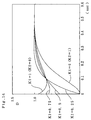
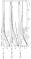
- Fig. 14 shows the relationship between the behaviour index value D and time, illustrating response simulation results for stepped inputs of ⁇ in the aforementioned transfer function G D (s).
- the vehicle speed V is set to a uniform value (16.7 m/s) and K1 is changed from 0 to 1 in steps of 0.25.
- Figs. 15(1) through (4) show relationships between time and behaviour index value D, illustrating response simulation results for stepped inputs of ⁇ in the aforementioned transfer function G D (s).
- K1 is taken as a constant value
- V vehicle speed
- the diagrams are similar to the response simulations illustrated in Fig. 14.
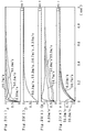
- Fig. 16(1) through (3) show the relationship between the behaviour index value D and time, illustrating response simulation results for stepped inputs of D* in the simulation model shown in Fig. 17.
- the transfer function G2 of ⁇ FF with respect to D* is taken as 1/G D (v), similarly to the first embodiment, in order to provide a comparison with the fourth embodiment.
- the transfer function of ⁇ with respect to ⁇ FF is approximated to the first order lag of the time constant 0.1 (sec), namely, 1/(0.1s + 1).
- the vehicle speed V is taken as 8.33 m/s, 16.7 m/s, 33.3 m/s, and 50.0 m/s.
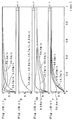
- Figs. 18(1) through (4) and Fig. 19 (1) through (4) show the relationships between time and the steering angle ⁇ , behaviour index value D, lateral acceleration Gy, and yaw rate ⁇ , illustrating response simulation results with respect to stepped inputs of D*, in a case where the transfer function G2 is taken as the inverse of G D (s) in the simulation model illustrated in Fig. 17.
- the vehicle speed V is taken as 8.33 m/s, 16.7 m/s, 33.3 m/s, and 50.0 m/s
- Figs. 19(1) through (4), K1 0.25.
- K1 and K2 are set as functions of the vehicle speed V, in such a manner that the transient response of the vehicle behaviour with respect to change in the steering angle corresponds to a previously determined given response, irrespective of the vehicle speed V.
- K1 is taken as a function of vehicle speed V as expressed by the following equation, in such a manner that the transient response of ⁇ at any vehicle speed coincides as closely as possible with the transient response at the vehicle speed in the model.
- K1 -0.0002205(V- 33.3) 2 + 0.245
- V 8.33 m/s
- K1 is adjusted to 0.10
- V 16.7 m/s
- K1 is adjusted to 0.19
- V 33.3 m/s
- K1 is adjusted to 0.25
- V 50.0 m/s
- K1 is amended to 0.19.
- Figs. 2 1(1) through (4) show response simulation results obtained using the aforementioned amended values for K1.
- Figs. 21(1) through (4) show response simulation results at the aforementioned vehicle velocities for ⁇ , D, Gy and ⁇ , respectively, with respect to stepped inputs of D*.
- the transfer function G3 of ⁇ FB with respect to the differential (D - D*) between the target behaviour index value D* and the behaviour index value D is taken as corresponding to the inverse of the aforementioned transfer function G D (s) of the behaviour index value D with respect to the steering angle ⁇ .
- Figs. 22(1) through (4) and Figs. 23 (1) through (4) respectively show the relationships between time and the steering angle ⁇ , behaviour index value D, lateral acceleration Gy and yaw rate ⁇ , illustrating response simulation results with respect to stepped inputs of D* in the simulation model illustrated in Fig. 24.
- the transfer function G2 is taken as the inverse of the transfer function G D (s) as described above, and moreover, the value of K1 is amended as a function of the vehicle speed V as described above.
- the transfer function G3 of ⁇ FB with respect to the differential (D - D*) is taken as a proportional control element, the proportional gain of which is taken as 1 in the response characteristics illustrated in Figs.
- the transfer function of ⁇ with respect to ⁇ * is approximated to the first order lag of the time-constant 0.1 (sec), namely 1/(0.1s + 1), apart from which the constitution is similar to the block diagram illustrating control of D with respect to D* in the first embodiment.
- the vehicle speed V is taken as 8.33 m/s, 16.7 m/s, 33.3 m/s and 50.0 m/s.
- the transfer function G3 of ⁇ FB with respect to (D* - D) is set by taking consideration of the transient response characteristics of the vehicle behaviour with respect to change in steering angle.
- the transfer function of ⁇ with respect to ⁇ * as G a .
- G3 (T b / T a - 1)/G D (s)
- the vehicle speed V is taken as 8.33 m/s, 16.7 m/s, 33.3 m/s, and 50.0 m/s.
- the broken lines indicate response simulation results for a vehicle speed of 8.33 m/s, in the simulation model illustrated in Fig. 17 where no controller of ⁇ FB with respect to (D* - D) is provided, and the single-dotted lines indicate response simulation results for a vehicle speed of 50.0 m/s in the same simulation model.
Abstract
Description
Claims (10)
- A steering device for a vehicle comprising:an operating member (1);a steering actuator (2) driven in accordance with operation of said operating member (1);means for transmitting the movement of said steering actuator (2) to the wheels (4) of a vehicle in such a manner that the steering angle changes in accordance with said movement, without said operating member (1) being coupled mechanically to said vehicle wheels (4);means (14, 15, 16, 20) for determining a behaviour index value corresponding to change in the behaviour of the vehicle;means (11, 12) for detecting the amount of operation of said operating member (1);means (20) for calculating a target behaviour index value corresponding to the detected amount of operation, on the basis of a stored relationship between the amount of operation and the target behaviour index value;means (20) for calculating a steering angle set value corresponding to the calculated target behaviour index value, on the basis of a stored relationship between the target behaviour index value and the steering angle set value;means (20) for calculating a steering angle correction value corresponding to the differential between the target behaviour index value and said determined behaviour index value, on the basis of a stored relationship between this differential and the steering angle correction value; andmeans (20) for controlling said steering actuator (2) in such a manner that the steering angle corresponds to a target steering angle being the sum of the steering angle set value and the steering angle correction value.
- The steering device for a vehicle according to claim 1, wherein the stored relationship between the target behaviour index value and the steering angle set value corresponds to the inverse of the transfer function of the behaviour index value with respect to the steering angle.
- The steering device for a vehicle according to claim 1 or 2, wherein the stored relationship between the differential of the target behaviour index value and the behaviour index value, and the steering angle correction value, corresponds to the inverse of the transfer function of the behaviour index value with respect to the steering angle.
- The steering device for a vehicle according to any one of claims 1 to 3, wherein said target behaviour index value is calculated in such a manner that the ratio of the yaw rate or lateral acceleration of the vehicle with respect to the amount of operation of the operating member (1) is uniform irrespective of the vehicle speed.
- The steering device for a vehicle according to any one of claims 1 to 4,
wherein said operating member (1) is rotationally operated;the amount of operation of said operating member (1) is taken as the operating torque imparted to the operating member (1) by the driver of the vehicle;and an operating actuator (19) for generating a reactive torque acting on the operating member (1) is provided;said steering device further comprising:means (11) for detecting the rotational operating angle of the operating member (1) due to the action of the differential between the detecting operating torque and the generated reactive torque;means (20) for calculating a target reactive torque corresponding to the detected rotational operating angle, on the basis of a stored relationship between the rotational operating angle and the target reactive torque; andmeans (20) for controlling the operating actuator (19) in such a manner that the reactive torque corresponds to the target reactive torque. - The steering device for a vehicle according to any one of claims 1 to 4,
wherein said operating member (1) is rotationally operated;the amount of operation of said operating member (1) is taken as the operating torque imparted to the operating member (1) by the driver of the vehicle;and an operating actuator (19) for generating a reactive torque acting on the operating member (1) is provided;said steering device further comprising:means (11) for detecting the rotational operating angle of the operating member (1) due to the action of the differential between the detecting operating torque and the generated reactive torque;means (20) for calculating a reactive torque set value corresponding to the detected rotational operating angle, on the basis of a stored relationship between the rotational operating angle and the reactive torque set value;means (20) for calculating a behaviour-related rotational operating angle for the operating member (1) corresponding to the determined behaviour index value, on the basis of a stored relationship between the behaviour index value and the behaviour-related rotational operating angle;means (20) for calculating a reactive torque correction value corresponding to the differential between the detected rotational operating angle and the calculated behaviour-related rotational operating angle, on the basis of a stored relationship between this differential and the reactive torque correction value; andmeans (20) for controlling the operating actuator (19) in such a manner that the reactive torque corresponds to a target reactive torque being the sum of the reactive torque set value and the reactive torque correction value. - The steering device for a vehicle according to claim 6, wherein the reactive torque correction value is taken as zero, at speeds lower than a previously set vehicle speed.
- The steering device for a vehicle according to any one of claims 1 to 7, wherein, at speeds lower than a previously set vehicle speed, a target steering angle corresponding to the detected amount of operation of the operating member (1) is calculated on the basis of a stored relationship between the amount of operation of the operating member (1) and the target steering angle, and the steering angle correction value is taken as zero.
- The steering device for a vehicle according to any one of claims 1 to 8, wherein, when the lateral acceleration of the vehicle is taken as Gy, the yaw rate of the vehicle as γ, the speed of the vehicle as V, the weighted ratio of the lateral acceleration as K1, the weighted ratio of the yaw rate as K2, andthe stored relationship between the target behaviour index value and the steering angle set value corresponds to the inverse of the transfer function of the behaviour index value with respect to the steering angle, andthe transfer function of the behaviour index value with respect to the steering angle is derived on the basis of a previously determined equation of motion containing the lateral acceleration, yaw rate, steering angle and speed of the vehicle as unknown quantities, in such a manner that at least one of either K1 or K2 is included therein, so that said function corresponds to the transient response of the vehicle behaviour with respect to change in the steering angle.
- The steering device for a vehicle according to claim 9, wherein K1 and K2 are taken as functions of the vehicle speed, in such a manner that the transient response of the vehicle behaviour with respect to change in the steering angle corresponds to a previously determined uniform response irrespective of the vehicle speed.
Applications Claiming Priority (4)
| Application Number | Priority Date | Filing Date | Title |
|---|---|---|---|
| JP31278999 | 1999-11-02 | ||
| JP31278999 | 1999-11-02 | ||
| JP35745199A JP4355874B2 (en) | 1999-11-02 | 1999-12-16 | Vehicle steering system |
| JP35745199 | 1999-12-16 |
Publications (3)
| Publication Number | Publication Date |
|---|---|
| EP1097855A2 true EP1097855A2 (en) | 2001-05-09 |
| EP1097855A3 EP1097855A3 (en) | 2001-07-25 |
| EP1097855B1 EP1097855B1 (en) | 2002-12-18 |
Family
ID=26567324
Family Applications (1)
| Application Number | Title | Priority Date | Filing Date |
|---|---|---|---|
| EP20000122793 Expired - Lifetime EP1097855B1 (en) | 1999-11-02 | 2000-10-19 | Steering device for vehicle |
Country Status (3)
| Country | Link |
|---|---|
| EP (1) | EP1097855B1 (en) |
| JP (1) | JP4355874B2 (en) |
| DE (1) | DE60001040T2 (en) |
Cited By (13)
| Publication number | Priority date | Publication date | Assignee | Title |
|---|---|---|---|---|
| US6588540B2 (en) * | 2001-07-26 | 2003-07-08 | Delphi Technologies, Inc. | Steer-by-wire redundant handwheel control |
| EP1362765A2 (en) * | 2002-05-15 | 2003-11-19 | Koyo Seiko Co., Ltd. | Vehicle steering apparatus |
| EP1380490A2 (en) * | 2002-07-12 | 2004-01-14 | Toyoda Koki Kabushiki Kaisha | Vehicle operation control method and vehicle operation control apparatus |
| EP1300320A3 (en) * | 2001-10-05 | 2004-03-24 | Koyo Seiko Co., Ltd. | Electric power steering apparatus |
| EP1577194A1 (en) * | 2004-03-16 | 2005-09-21 | Toyoda Koki Kabushiki Kaisha | Steering apparatus for vehicle and method for controlling the same |
| EP1714853A3 (en) * | 2005-04-19 | 2007-03-07 | Jtekt Corporation | Electric power steering apparatus |
| US7581616B2 (en) | 2004-01-07 | 2009-09-01 | Toyota Jidosha Kobushiki Kaisha | Control system for a steer-by-wire vehicle |
| US8177019B2 (en) * | 2006-12-28 | 2012-05-15 | Jtekt Corporation | Steering device for vehicle |
| US8660749B2 (en) | 2006-05-09 | 2014-02-25 | Jtekt Corporation | Motor vehicle steering system |
| CN105818855A (en) * | 2015-01-22 | 2016-08-03 | 株式会社万都 | Electric power steering apparatus and method of controlling the same |
| CN111712413A (en) * | 2018-02-19 | 2020-09-25 | 马自达汽车株式会社 | Vehicle control device |
| CN114802442A (en) * | 2022-05-06 | 2022-07-29 | 小米汽车科技有限公司 | Vehicle transverse control method and device, storage medium and vehicle |
| US20220250678A1 (en) * | 2021-02-08 | 2022-08-11 | Continental Automotive Gmbh | Regulating device and method for regulating the steering angle of a vehicle |
Families Citing this family (9)
| Publication number | Priority date | Publication date | Assignee | Title |
|---|---|---|---|---|
| JP4952872B2 (en) * | 2001-08-07 | 2012-06-13 | 株式会社ジェイテクト | Vehicle steering system |
| JP3940056B2 (en) | 2002-10-11 | 2007-07-04 | アイシン精機株式会社 | Road surface state estimation device and vehicle motion control device including the device |
| JP3964771B2 (en) | 2002-10-11 | 2007-08-22 | 株式会社豊田中央研究所 | Road surface state estimation device and vehicle motion control device including the device |
| JP4511815B2 (en) | 2003-09-26 | 2010-07-28 | アイシン精機株式会社 | Suspension control device |
| JP4379261B2 (en) * | 2004-08-30 | 2009-12-09 | 日産自動車株式会社 | Vehicle steering system |
| KR101393195B1 (en) | 2010-01-29 | 2014-05-08 | 주식회사 만도 | Method and System for Recognizing Absolute Steering Wheel Angle |
| JP2012096742A (en) * | 2010-11-05 | 2012-05-24 | Nippon Yusoki Co Ltd | Steer-by-wire type steering device |
| JP5807778B2 (en) * | 2011-09-15 | 2015-11-10 | 株式会社ジェイテクト | Steering device for cargo handling vehicle |
| JP7355628B2 (en) | 2019-12-05 | 2023-10-03 | Toyo Tire株式会社 | System, method and program for evaluating high-speed straight running stability of tires |
Family Cites Families (1)
| Publication number | Priority date | Publication date | Assignee | Title |
|---|---|---|---|---|
| JPH04133860A (en) * | 1990-09-25 | 1992-05-07 | Honda Motor Co Ltd | Control method for vehicle steering device |
-
1999
- 1999-12-16 JP JP35745199A patent/JP4355874B2/en not_active Expired - Fee Related
-
2000
- 2000-10-19 EP EP20000122793 patent/EP1097855B1/en not_active Expired - Lifetime
- 2000-10-19 DE DE2000601040 patent/DE60001040T2/en not_active Expired - Lifetime
Non-Patent Citations (1)
| Title |
|---|
| None |
Cited By (21)
| Publication number | Priority date | Publication date | Assignee | Title |
|---|---|---|---|---|
| US6588540B2 (en) * | 2001-07-26 | 2003-07-08 | Delphi Technologies, Inc. | Steer-by-wire redundant handwheel control |
| EP1300320A3 (en) * | 2001-10-05 | 2004-03-24 | Koyo Seiko Co., Ltd. | Electric power steering apparatus |
| US6892120B2 (en) | 2001-10-05 | 2005-05-10 | Koyo Seiko, Co., Ltd. | Electric power steering apparatus |
| EP1362765A2 (en) * | 2002-05-15 | 2003-11-19 | Koyo Seiko Co., Ltd. | Vehicle steering apparatus |
| US6719088B2 (en) | 2002-05-15 | 2004-04-13 | Koyo Seiko Co., Ltd. | Vehicle steering apparatus |
| EP1362765A3 (en) * | 2002-05-15 | 2006-04-12 | Koyo Seiko Co., Ltd. | Vehicle steering apparatus |
| EP1380490A2 (en) * | 2002-07-12 | 2004-01-14 | Toyoda Koki Kabushiki Kaisha | Vehicle operation control method and vehicle operation control apparatus |
| EP1380490A3 (en) * | 2002-07-12 | 2004-08-11 | Toyoda Koki Kabushiki Kaisha | Vehicle operation control method and vehicle operation control apparatus |
| US7581616B2 (en) | 2004-01-07 | 2009-09-01 | Toyota Jidosha Kobushiki Kaisha | Control system for a steer-by-wire vehicle |
| US7426428B2 (en) | 2004-03-16 | 2008-09-16 | Toyoda Koki Kabushiki Kaisha | Steering apparatus for vehicle and method for controlling the same |
| EP1577194A1 (en) * | 2004-03-16 | 2005-09-21 | Toyoda Koki Kabushiki Kaisha | Steering apparatus for vehicle and method for controlling the same |
| US7349781B2 (en) | 2005-04-19 | 2008-03-25 | Jtekt Corporation | Electric power steering apparatus |
| EP1714853A3 (en) * | 2005-04-19 | 2007-03-07 | Jtekt Corporation | Electric power steering apparatus |
| US8660749B2 (en) | 2006-05-09 | 2014-02-25 | Jtekt Corporation | Motor vehicle steering system |
| US8177019B2 (en) * | 2006-12-28 | 2012-05-15 | Jtekt Corporation | Steering device for vehicle |
| CN105818855A (en) * | 2015-01-22 | 2016-08-03 | 株式会社万都 | Electric power steering apparatus and method of controlling the same |
| CN105818855B (en) * | 2015-01-22 | 2019-01-04 | 株式会社万都 | Electrically powered steering apparatus using same and the method for controlling the electrically powered steering apparatus using same |
| CN111712413A (en) * | 2018-02-19 | 2020-09-25 | 马自达汽车株式会社 | Vehicle control device |
| US20220250678A1 (en) * | 2021-02-08 | 2022-08-11 | Continental Automotive Gmbh | Regulating device and method for regulating the steering angle of a vehicle |
| CN114802442A (en) * | 2022-05-06 | 2022-07-29 | 小米汽车科技有限公司 | Vehicle transverse control method and device, storage medium and vehicle |
| CN114802442B (en) * | 2022-05-06 | 2023-09-05 | 小米汽车科技有限公司 | Vehicle transverse control method and device, storage medium and vehicle |
Also Published As
| Publication number | Publication date |
|---|---|
| DE60001040D1 (en) | 2003-01-30 |
| DE60001040T2 (en) | 2009-10-01 |
| EP1097855B1 (en) | 2002-12-18 |
| JP4355874B2 (en) | 2009-11-04 |
| JP2001191937A (en) | 2001-07-17 |
| EP1097855A3 (en) | 2001-07-25 |
Similar Documents
| Publication | Publication Date | Title |
|---|---|---|
| EP1097855B1 (en) | Steering device for vehicle | |
| EP1362765B1 (en) | Vehicle steering apparatus | |
| JP3636926B2 (en) | Vehicle steering system | |
| US5606502A (en) | Steering angle control system for vehicle | |
| US6449543B2 (en) | Steering device for vehicle | |
| CN112519882B (en) | Vehicle reference track tracking method and system | |
| JPS62155170A (en) | Control device for steering reaction force | |
| JPH07196048A (en) | Electric power steering device | |
| JP4032985B2 (en) | Vehicle motion control device | |
| JP3593898B2 (en) | Steering control device | |
| JP3611116B2 (en) | Electric power steering control device | |
| JP3360528B2 (en) | Vehicle motion control device | |
| JP4238953B2 (en) | Vehicle steering system | |
| EP1088739B1 (en) | Motor vehicle steering system | |
| JP3463530B2 (en) | Vehicle motion control device | |
| JP2518245B2 (en) | Rear wheel steering system for vehicles | |
| JP2003011838A (en) | Vehicular steering gear | |
| JP4604631B2 (en) | Vehicle steering control device | |
| JP3282698B2 (en) | Auxiliary steering angle control device for vehicles | |
| JPH06316273A (en) | Rear-wheel steering angle controller of four-wheel steering car | |
| JP3102104B2 (en) | Vehicle steering angle control device | |
| JP2982596B2 (en) | Auxiliary steering angle control device for vehicles | |
| CN116373992A (en) | Road feel torque determination method and device for steer-by-wire system and storage medium | |
| JP2023159537A (en) | Control device of vehicle steering system | |
| JP2874474B2 (en) | Four-wheel steering control device |
Legal Events
| Date | Code | Title | Description |
|---|---|---|---|
| PUAI | Public reference made under article 153(3) epc to a published international application that has entered the european phase |
Free format text: ORIGINAL CODE: 0009012 |
|
| AK | Designated contracting states |
Kind code of ref document: A2 Designated state(s): DE FR GB IT |
|
| AX | Request for extension of the european patent |
Free format text: AL;LT;LV;MK;RO;SI |
|
| PUAL | Search report despatched |
Free format text: ORIGINAL CODE: 0009013 |
|
| AK | Designated contracting states |
Kind code of ref document: A3 Designated state(s): AT BE CH CY DE DK ES FI FR GB GR IE IT LI LU MC NL PT SE |
|
| AX | Request for extension of the european patent |
Free format text: AL;LT;LV;MK;RO;SI |
|
| 17P | Request for examination filed |
Effective date: 20010706 |
|
| 17Q | First examination report despatched |
Effective date: 20011120 |
|
| GRAG | Despatch of communication of intention to grant |
Free format text: ORIGINAL CODE: EPIDOS AGRA |
|
| AKX | Designation fees paid |
Free format text: DE FR GB IT |
|
| GRAG | Despatch of communication of intention to grant |
Free format text: ORIGINAL CODE: EPIDOS AGRA |
|
| GRAH | Despatch of communication of intention to grant a patent |
Free format text: ORIGINAL CODE: EPIDOS IGRA |
|
| GRAG | Despatch of communication of intention to grant |
Free format text: ORIGINAL CODE: EPIDOS AGRA |
|
| GRAH | Despatch of communication of intention to grant a patent |
Free format text: ORIGINAL CODE: EPIDOS IGRA |
|
| GRAH | Despatch of communication of intention to grant a patent |
Free format text: ORIGINAL CODE: EPIDOS IGRA |
|
| GRAH | Despatch of communication of intention to grant a patent |
Free format text: ORIGINAL CODE: EPIDOS IGRA |
|
| GRAA | (expected) grant |
Free format text: ORIGINAL CODE: 0009210 |
|
| AK | Designated contracting states |
Kind code of ref document: B1 Designated state(s): DE FR GB IT |
|
| REG | Reference to a national code |
Ref country code: GB Ref legal event code: FG4D |
|
| REF | Corresponds to: |
Kind code of ref document: P Ref document number: 60001040 Country of ref document: DE Date of ref document: 20030130 |
|
| ET | Fr: translation filed | ||
| PLBE | No opposition filed within time limit |
Free format text: ORIGINAL CODE: 0009261 |
|
| STAA | Information on the status of an ep patent application or granted ep patent |
Free format text: STATUS: NO OPPOSITION FILED WITHIN TIME LIMIT |
|
| 26N | No opposition filed |
Effective date: 20030919 |
|
| PGFP | Annual fee paid to national office [announced via postgrant information from national office to epo] |
Ref country code: IT Payment date: 20071029 Year of fee payment: 8 |
|
| PGFP | Annual fee paid to national office [announced via postgrant information from national office to epo] |
Ref country code: GB Payment date: 20071017 Year of fee payment: 8 |
|
| GBPC | Gb: european patent ceased through non-payment of renewal fee |
Effective date: 20081019 |
|
| PG25 | Lapsed in a contracting state [announced via postgrant information from national office to epo] |
Ref country code: IT Free format text: LAPSE BECAUSE OF NON-PAYMENT OF DUE FEES Effective date: 20081019 |
|
| PG25 | Lapsed in a contracting state [announced via postgrant information from national office to epo] |
Ref country code: GB Free format text: LAPSE BECAUSE OF NON-PAYMENT OF DUE FEES Effective date: 20081019 |
|
| PGFP | Annual fee paid to national office [announced via postgrant information from national office to epo] |
Ref country code: DE Payment date: 20141014 Year of fee payment: 15 Ref country code: FR Payment date: 20141008 Year of fee payment: 15 |
|
| REG | Reference to a national code |
Ref country code: DE Ref legal event code: R119 Ref document number: 60001040 Country of ref document: DE |
|
| PG25 | Lapsed in a contracting state [announced via postgrant information from national office to epo] |
Ref country code: DE Free format text: LAPSE BECAUSE OF NON-PAYMENT OF DUE FEES Effective date: 20160503 |
|
| REG | Reference to a national code |
Ref country code: FR Ref legal event code: ST Effective date: 20160630 |
|
| PG25 | Lapsed in a contracting state [announced via postgrant information from national office to epo] |
Ref country code: FR Free format text: LAPSE BECAUSE OF NON-PAYMENT OF DUE FEES Effective date: 20151102 |