EP1097849A1 - Wiper assembly - Google Patents
Wiper assembly Download PDFInfo
- Publication number
- EP1097849A1 EP1097849A1 EP99203734A EP99203734A EP1097849A1 EP 1097849 A1 EP1097849 A1 EP 1097849A1 EP 99203734 A EP99203734 A EP 99203734A EP 99203734 A EP99203734 A EP 99203734A EP 1097849 A1 EP1097849 A1 EP 1097849A1
- Authority
- EP
- European Patent Office
- Prior art keywords
- wiper
- wiper assembly
- deflecting
- assembly according
- angle
- Prior art date
- Legal status (The legal status is an assumption and is not a legal conclusion. Google has not performed a legal analysis and makes no representation as to the accuracy of the status listed.)
- Withdrawn
Links
- 239000012530 fluid Substances 0.000 claims abstract description 43
- 239000007787 solid Substances 0.000 claims abstract description 16
- 238000004140 cleaning Methods 0.000 claims abstract description 15
- 239000007788 liquid Substances 0.000 claims abstract description 5
- 238000010438 heat treatment Methods 0.000 claims description 2
- 239000002184 metal Substances 0.000 description 8
- 230000000712 assembly Effects 0.000 description 6
- 238000000429 assembly Methods 0.000 description 6
- 238000002347 injection Methods 0.000 description 6
- 239000007924 injection Substances 0.000 description 6
- 230000008859 change Effects 0.000 description 5
- 239000000463 material Substances 0.000 description 4
- 238000000034 method Methods 0.000 description 4
- 239000013536 elastomeric material Substances 0.000 description 2
- 239000011521 glass Substances 0.000 description 2
- 239000012535 impurity Substances 0.000 description 2
- 238000010348 incorporation Methods 0.000 description 2
- 230000037361 pathway Effects 0.000 description 2
- 239000006185 dispersion Substances 0.000 description 1
- 238000011156 evaluation Methods 0.000 description 1
- 238000004519 manufacturing process Methods 0.000 description 1
- 229920000515 polycarbonate Polymers 0.000 description 1
- 239000004417 polycarbonate Substances 0.000 description 1
- 229920000642 polymer Polymers 0.000 description 1
- 230000008569 process Effects 0.000 description 1
- 238000006748 scratching Methods 0.000 description 1
- 230000002393 scratching effect Effects 0.000 description 1
- 239000007921 spray Substances 0.000 description 1
- 238000003892 spreading Methods 0.000 description 1
- 230000007480 spreading Effects 0.000 description 1
- 238000003466 welding Methods 0.000 description 1
Images


Classifications
-
- B—PERFORMING OPERATIONS; TRANSPORTING
- B60—VEHICLES IN GENERAL
- B60S—SERVICING, CLEANING, REPAIRING, SUPPORTING, LIFTING, OR MANOEUVRING OF VEHICLES, NOT OTHERWISE PROVIDED FOR
- B60S1/00—Cleaning of vehicles
- B60S1/02—Cleaning windscreens, windows or optical devices
- B60S1/04—Wipers or the like, e.g. scrapers
- B60S1/32—Wipers or the like, e.g. scrapers characterised by constructional features of wiper blade arms or blades
- B60S1/38—Wiper blades
- B60S1/3806—Means, or measures taken, for influencing the aerodynamic quality of the wiper blades
-
- B—PERFORMING OPERATIONS; TRANSPORTING
- B60—VEHICLES IN GENERAL
- B60S—SERVICING, CLEANING, REPAIRING, SUPPORTING, LIFTING, OR MANOEUVRING OF VEHICLES, NOT OTHERWISE PROVIDED FOR
- B60S1/00—Cleaning of vehicles
- B60S1/02—Cleaning windscreens, windows or optical devices
- B60S1/46—Cleaning windscreens, windows or optical devices using liquid; Windscreen washers
- B60S1/48—Liquid supply therefor
- B60S1/52—Arrangement of nozzles; Liquid spreading means
- B60S1/522—Arrangement of nozzles; Liquid spreading means moving liquid spreading means, e.g. arranged in wiper arms
- B60S1/524—Arrangement of nozzles; Liquid spreading means moving liquid spreading means, e.g. arranged in wiper arms arranged in wiper blades
Definitions
- the present invention concerns a wiper assembly for cleaning a solid surface, by means of a fluid, suitable for cleaning a windscreen of an automotive vehicle.
- Wiper assemblies are used to clean solid surfaces on which impurities contained in an atmosphere become deposited.
- the principle of this cleaning process consists in moistening of the surface with a fluid and to move pivotally a wiper blade across the surface to remove the fluid containing impurities.
- Examples of commercialised wiper assemblies include, amongst others, windscreen wiper assemblies for automotive vehicles such as cars or trucks and wiper assemblies for cleaning the glass screen of headlights. Criteria of evaluation of wiper assemblies include good moistening of the surface necessary to avoid scratching and low fluid consumption.
- the invention intends to solve these problems.
- the invention concerns a wiper assembly capable of removing liquid from a solid surface, suitable for cleaning a windscreen of an automotive vehicle, said wiper assembly comprising a movable wiper blade, said wiper blade being attached to a wiper arm, connected to driving means, said wiper assembly further comprising at least a fluid dispensing device comprising
- the wiper assembly according to the invention which directs essentially all of the fluid on a short pathway substantially parallel to the wiper blade towards the surface to be cleaned, enables for reliable moistening of the surface at low cleaning liquid consumption.
- the driving means may consist in a known system capable to bring about a pivotal or translational movement of the wiper assembly across a substantially plane surface.
- Known wiper blades may be used in the wiper assembly according to the invention.
- the part of the wiper blade which comes into contact with the solid surface during operation is made from an elastomeric material such as rubber.
- the shape of the wiper blade may be straight or curved with regard to its end points.
- the wiper blade is often supported on a rearside, preferably made from metal or rigid polymeric material, which conveys rigidity to the wiper blade and establishes the connection to the wiper arm.
- the solid surface to be cleaned is generally substantially planar.
- the surface is often transparent and may be made for example from materials such as glass or rigid polymer such as for example polycarbonates.
- the means for projecting a fluid generally comprises an injection nozzle connected to a fluid pump.
- Suitable fluid pumps are known and supply fluid at a pressure sufficient to project a beam to moisten the surface when the beam is directed towards it by the directing means.
- the connection between the pump and the injection nozzle may be brought about by known techniques.
- a flexible tube connection, made, for example, from elastomeric material is preferred.
- the injection nozzle comprises at least one outlet.
- the injection nozzle is generally shaped to project a homogeneous, non dispersed beam in order to allow for precise deflection of the beam by the means for deflecting.
- the Figure 1 depicts the definition of the angle a.
- the points A and B stand for the end points of the wiper blade.
- the point C stands for the outlet of the means for projecting.
- the angle of the beam E projected from the outlet C of the means for projecting is the angle ⁇ between the beam E and the plane D defined by the points A, B and C.
- the angle ⁇ lies in a second plane F, perpendicular to the plane D.
- the angle ⁇ is generally at least about 10°. Often the angle is at least 30°. An angle of at least 45° is particularly suitable. An angle of at least 60° is preferred. The angle is generally at most about 170°. Often the angle is at most about 150°. An angle of about at most 135° is particularly suitable. An angle of at most 60° is preferred. An angle from about 75 to about 115° is specially preferred. An angle of about 90° is most preferred.
- the means for projecting a beam of fluid and the means for deflecting the beam are attached to the wiper blade or on the wiper arm or incorporated into the wiper blade or into the wiper arm.
- the means for projecting a beam of fluid and the means for deflecting the beam may be attached to the wiper blade or to the wiper arm by known techniques.
- the means for deflecting is attached to the means for projecting and the means for projecting is attached to the wiper blade or the wiper arm.
- the means for projecting a beam of fluid into the rearside of the wiper blade or into the wiper arm.
- the incorporation of the means for projecting the fluid into the rearside of the wiper blade or into the wiper arm has aerodynamic advantages as the wiper arm and backing will act as a shield with regard to the beam projected.
- the incorporation may also facilitate mounting of the wiper assembly and protect the means for projecting, which may be made from relatively fragile material, against mechanical damage.
- the means for projecting is attached to the wiper blade or to the wiper arm or incorporated into the wiper blade or into the wiper arm in such a way that the outlet points in the angle described above.
- At least one means for projecting is incorporated into a rearside of the wiperblade next to the point of attachment of said rearside to the wiper arm and a means for deflecting is attached to the rearside so as to be able to deflect a beam coming from the incorporated means for projecting during operation.
- the wiper assembly of the invention comprises more than one fluid dispensing device.
- the means for deflecting usually brings about a change of the initial direction of the beam E of at least 45°. Often the change of direction is at least 60°. Preferably, the change of direction is at least 75°. Changes of direction of about 90° give excellent results.
- a particular case illustrating the change of direction is given in Figure 1, where the angle ⁇ enclosed between E and G and said angle lying in the plane F corresponds to the change of direction.
- the means for deflecting comprises at least one deflecting face.
- the deflector may be made, for example from polymeric material or metal. Preferably the deflector is a bent piece of metal.
- the means for deflecting comprises at least two deflecting faces. Most preferably, it comprises two deflecting faces.
- the angle ⁇ between two deflecting faces is generally at least about 80°. Preferably, the angle is from at least about 90°. Generally the angle is at most about 150°. Preferably the angle is at most about 140°.
- FIG 2 (a) and 2 (b) show a preferred means for deflecting usable in the wiper assembly of the invention.
- Figure 2(a) shows the front view on the means for deflecting.
- Figure 2 (b) shows the side view on the means for deflecting.
- This means for deflecting is a substantially round plate, preferably made from metal, having two deflecting faces forming an angle ⁇ of about 110°.
- the preferred distance between the outlet and the point where the means for deflecting said beam towards the solid surface is hit by said beam depends on the pump pressure and the desired distance between the wiper blade and the zone of the surface to be moistened by the fluid.
- the distance between the outlet and the point where the means for deflecting said beam towards the solid surface is hit by said beam is at least 1 mm.
- the distance is at least 2 mm.
- Excellent results are obtained at a distance of at least 5 mm.
- the distance between the outlet and the point where the means for deflecting said beam towards the solid surface is hit by said beam is at most 50 mm.
- the distance is at most 30 mm. Excellent results are obtained at a distance of at most 25 mm.
- the means for deflecting is attached to the wiper blade or to the wiper arm or to the means for projecting so as to be able to direct the beam of fluid coming from the means for projecting towards the surface.
- the means for deflecting may be fixed by known techniques. When the means for deflecting is made from metal, welding of said piece to a metal rearside of the wiper blade or to a metal wiper arm or to the means for projecting made from metal is preferred.
- the first direction G is in the plane F and is substantially perpendicular to the initial direction of the beam E.
- the second and third directions H and I are out of the plane F.
- the dispersion angles ⁇ et ⁇ are generally at least 10° relative to the plane F. Often the angles are at least 30°. Preferably the angles are at least 45°.
- the second and third directions are substantially symmetrical to the plane F, so that ⁇ is substantially equal to ⁇ .
- the figure 3 shows a partial view of a particular wiper assembly according to the invention showing a fluid dispensing device, comprising the elements (2), (3), (4) and (5) said fluid dispensing device being connected to a fluid tube (1) and being attached to the rearside (6) of a wiper blade (7).
- the means for projecting comprises an injection nozzle (2) having an outlet (3) and being connected to a fluid tube (1).
- the means for deflecting is a deflector according to Figure 2 (4) attached to the injection nozzle through an attachment structure (5).
- the number of fluid dispensing devices to be preferably used depends on the length of the wiper blade, the geometry of the means for deflecting the beam and the pump pressure. Very low cleaning liquid consumption may be achieved, as the pathway of the fluid becomes shorter in comparison to wiper assemblies comprising one device.
- the fluid dispensing device may further comprise a heating element known as such.
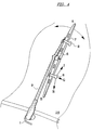
- FIG 4 shows a wiper assembly according to the invention during use for cleaning a solid surface (10).
- the wiper assembly comprises a movable wiper arm (9), a wiper blade (7) with a rearside (6) and, attached thereto, two fluid dispensing devices (8) according to Figure 3, comprising elements 2,3,4 and 5, said devices (8) being connected to a fluid pipe (1). It is further shown, that each fluid dispensing device disperses a beam of fluid towards the solid surface (10) in the three principal direction G, H and I according to Figure 1.
- the wiper assembly of the invention is particularly useful to remove fluids from transparent surfaces in automotive applications such as the removal of fluid from an automotive windscreen and cleaning of said windscreen or the removal of fluid from an automotive headglass and cleaning of said headglass.
- the invention concerns also the use of the wiper assembly according to the invention for cleaning a transparent surface. Specifically the invention concerns the use of the wiper assembly according to the invention for cleaning a transparent surface in automotive applications.
Landscapes
- Engineering & Computer Science (AREA)
- Mechanical Engineering (AREA)
- Physics & Mathematics (AREA)
- Fluid Mechanics (AREA)
- Quality & Reliability (AREA)
- Water Supply & Treatment (AREA)
- Cleaning In General (AREA)
Abstract
A wiper assembly capable of removing liquid from a solid surface (10), suitable
for cleaning a windscreen of an automotive vehicle, said wiper assembly
comprising a movable wiper blade (6), a wiper arm (9), said wiper assembly
further comprising at least a fluid dispensing device (8).
Description
- The present invention concerns a wiper assembly for cleaning a solid surface, by means of a fluid, suitable for cleaning a windscreen of an automotive vehicle.
- Wiper assemblies are used to clean solid surfaces on which impurities contained in an atmosphere become deposited. The principle of this cleaning process consists in moistening of the surface with a fluid and to move pivotally a wiper blade across the surface to remove the fluid containing impurities. Examples of commercialised wiper assemblies include, amongst others, windscreen wiper assemblies for automotive vehicles such as cars or trucks and wiper assemblies for cleaning the glass screen of headlights. Criteria of evaluation of wiper assemblies include good moistening of the surface necessary to avoid scratching and low fluid consumption.
- In US 3793670 a windshield washer assembly is proposed, in which a stream of fluid is projected against a baffle and dispersed into a broad spray directed toward the windshield. When this known assembly is used, fluid consumption may be high due to air currents carrying away a part of the fluid from the zones of the windshield across which the wiper blade moves. With regard to this known windshield washer assembly, it was desirable to find a wiper assembly which ensures good moistening of the surface at low fluid consumption and is easy to manufacture.
- The invention intends to solve these problems.
- The invention concerns a wiper assembly capable of removing liquid from a solid surface, suitable for cleaning a windscreen of an automotive vehicle, said wiper assembly comprising a movable wiper blade, said wiper blade being attached to a wiper arm, connected to driving means, said wiper assembly further comprising at least a fluid dispensing device comprising
- (a) at least a means for projecting a beam of fluid at an angle essentially out of the plane defined by the two end points of the wiper blade and the outlet of said means for projecting, and
- (b) at least a means for deflecting and spreading the beam in a direction
substantially perpendicular to the initial direction of the beam so as to be
able to spread said beam, during operation, towards an area of the solid
surface extending approximately parallel to the wiper blade,
said fluid dispensing device being attached to the wiper arm or the wiper blade. -
- Surprisingly, it has been found that the wiper assembly according to the invention, which directs essentially all of the fluid on a short pathway substantially parallel to the wiper blade towards the surface to be cleaned, enables for reliable moistening of the surface at low cleaning liquid consumption.
- In the wiper assembly according to the invention, the driving means may consist in a known system capable to bring about a pivotal or translational movement of the wiper assembly across a substantially plane surface. Known wiper blades may be used in the wiper assembly according to the invention. Preferably the part of the wiper blade which comes into contact with the solid surface during operation is made from an elastomeric material such as rubber. The shape of the wiper blade may be straight or curved with regard to its end points. The wiper blade is often supported on a rearside, preferably made from metal or rigid polymeric material, which conveys rigidity to the wiper blade and establishes the connection to the wiper arm. The solid surface to be cleaned is generally substantially planar. The surface is often transparent and may be made for example from materials such as glass or rigid polymer such as for example polycarbonates.
- In the wiper assembly of the invention, the means for projecting a fluid generally comprises an injection nozzle connected to a fluid pump. Suitable fluid pumps are known and supply fluid at a pressure sufficient to project a beam to moisten the surface when the beam is directed towards it by the directing means. The connection between the pump and the injection nozzle may be brought about by known techniques. A flexible tube connection, made, for example, from elastomeric material is preferred. The injection nozzle comprises at least one outlet. The injection nozzle is generally shaped to project a homogeneous, non dispersed beam in order to allow for precise deflection of the beam by the means for deflecting.
- The Figure 1 depicts the definition of the angle a. The points A and B stand for the end points of the wiper blade. The point C stands for the outlet of the means for projecting. The angle of the beam E projected from the outlet C of the means for projecting is the angle α between the beam E and the plane D defined by the points A, B and C. The angle α lies in a second plane F, perpendicular to the plane D.
- The angle α is generally at least about 10°. Often the angle is at least 30°. An angle of at least 45° is particularly suitable. An angle of at least 60° is preferred. The angle is generally at most about 170°. Often the angle is at most about 150°. An angle of about at most 135° is particularly suitable. An angle of at most 60° is preferred. An angle from about 75 to about 115° is specially preferred. An angle of about 90° is most preferred.
- In the wiper assembly of the invention, the means for projecting a beam of fluid and the means for deflecting the beam are attached to the wiper blade or on the wiper arm or incorporated into the wiper blade or into the wiper arm. The means for projecting a beam of fluid and the means for deflecting the beam may be attached to the wiper blade or to the wiper arm by known techniques. In a specific embodiment, the means for deflecting is attached to the means for projecting and the means for projecting is attached to the wiper blade or the wiper arm.
- It is preferred to incorporate the means for projecting a beam of fluid into the rearside of the wiper blade or into the wiper arm. The incorporation of the means for projecting the fluid into the rearside of the wiper blade or into the wiper arm has aerodynamic advantages as the wiper arm and backing will act as a shield with regard to the beam projected. The incorporation may also facilitate mounting of the wiper assembly and protect the means for projecting, which may be made from relatively fragile material, against mechanical damage. Suitably the means for projecting is attached to the wiper blade or to the wiper arm or incorporated into the wiper blade or into the wiper arm in such a way that the outlet points in the angle described above.
- In a specific embodiment, at least one means for projecting is incorporated into a rearside of the wiperblade next to the point of attachment of said rearside to the wiper arm and a means for deflecting is attached to the rearside so as to be able to deflect a beam coming from the incorporated means for projecting during operation.
- In a further specific embodiment, the wiper assembly of the invention comprises more than one fluid dispensing device.
- The means for deflecting usually brings about a change of the initial direction of the beam E of at least 45°. Often the change of direction is at least 60°. Preferably, the change of direction is at least 75°. Changes of direction of about 90° give excellent results. A particular case illustrating the change of direction is given in Figure 1, where the angle ε enclosed between E and G and said angle lying in the plane F corresponds to the change of direction.
- The means for deflecting comprises at least one deflecting face. The deflector may be made, for example from polymeric material or metal. Preferably the deflector is a bent piece of metal.
- In a preferred embodiment, the means for deflecting comprises at least two deflecting faces. Most preferably, it comprises two deflecting faces. The angle δ between two deflecting faces is generally at least about 80°. Preferably, the angle is from at least about 90°. Generally the angle is at most about 150°. Preferably the angle is at most about 140°.
- The figure 2 (a) and 2 (b) show a preferred means for deflecting usable in the wiper assembly of the invention. Figure 2(a) shows the front view on the means for deflecting. Figure 2 (b) shows the side view on the means for deflecting. This means for deflecting is a substantially round plate, preferably made from metal, having two deflecting faces forming an angle δ of about 110°.
- The preferred distance between the outlet and the point where the means for deflecting said beam towards the solid surface is hit by said beam, depends on the pump pressure and the desired distance between the wiper blade and the zone of the surface to be moistened by the fluid. Generally, the distance between the outlet and the point where the means for deflecting said beam towards the solid surface is hit by said beam is at least 1 mm. Preferably, the distance is at least 2 mm. Excellent results are obtained at a distance of at least 5 mm. Generally, the distance between the outlet and the point where the means for deflecting said beam towards the solid surface is hit by said beam is at most 50 mm. Preferably, the distance is at most 30 mm. Excellent results are obtained at a distance of at most 25 mm.
- The means for deflecting is attached to the wiper blade or to the wiper arm or to the means for projecting so as to be able to direct the beam of fluid coming from the means for projecting towards the surface. The means for deflecting may be fixed by known techniques. When the means for deflecting is made from metal, welding of said piece to a metal rearside of the wiper blade or to a metal wiper arm or to the means for projecting made from metal is preferred.
- Good results are obtained with a geometry, in which the beam is dispersed essentially in three directions. Referring to Figure 1, the first direction G is in the plane F and is substantially perpendicular to the initial direction of the beam E. The second and third directions H and I are out of the plane F. The dispersion angles β et γ are generally at least 10° relative to the plane F. Often the angles are at least 30°. Preferably the angles are at least 45°. In a specific embodiment, the second and third directions are substantially symmetrical to the plane F, so that β is substantially equal to γ.
- The figure 3 shows a partial view of a particular wiper assembly according to the invention showing a fluid dispensing device, comprising the elements (2), (3), (4) and (5) said fluid dispensing device being connected to a fluid tube (1) and being attached to the rearside (6) of a wiper blade (7). The means for projecting comprises an injection nozzle (2) having an outlet (3) and being connected to a fluid tube (1). The means for deflecting is a deflector according to Figure 2 (4) attached to the injection nozzle through an attachment structure (5).
- The number of fluid dispensing devices to be preferably used depends on the length of the wiper blade, the geometry of the means for deflecting the beam and the pump pressure. Very low cleaning liquid consumption may be achieved, as the pathway of the fluid becomes shorter in comparison to wiper assemblies comprising one device.
- The fluid dispensing device may further comprise a heating element known as such.
- The invention is further illustrated in a non-limitative manner by figure 4, which shows a wiper assembly according to the invention during use for cleaning a solid surface (10). The wiper assembly comprises a movable wiper arm (9), a wiper blade (7) with a rearside (6) and, attached thereto, two fluid dispensing devices (8) according to Figure 3, comprising
elements - The wiper assembly of the invention is particularly useful to remove fluids from transparent surfaces in automotive applications such as the removal of fluid from an automotive windscreen and cleaning of said windscreen or the removal of fluid from an automotive headglass and cleaning of said headglass.
- Consequently, the invention concerns also the use of the wiper assembly according to the invention for cleaning a transparent surface. Specifically the invention concerns the use of the wiper assembly according to the invention for cleaning a transparent surface in automotive applications.
Claims (10)
- A wiper assembly capable of removing liquid from a solid surface (10), suitable for cleaning a windscreen of an automotive vehicle, said wiper assembly comprising a movable wiper blade (7), said wiper blade being attached to a wiper arm (9), connected to driving means, said wiper assembly further comprising at least one fluid dispensing device (8) comprising(a) at least one means for projecting a beam of fluid at an angle (α) essentially out of the plane defined by the two end points (A,B) of the wiper blade (7) and the outlet (C) of said means for projecting, and(b) at least one means (4) for deflecting the beam in a direction substantially perpendicular to the initial direction of the beam so as to be able to spread said beam, during operation, towards an area of the solid surface (10) extending approximately parallel to the wiper blade,
said fluid dispensing device (8) being attached to the wiper arm (9) or the wiper blade (7). - The wiper assembly according to claim 1, in which the angle (α) is at least 60°.
- The wiper assembly according to claim 1, in which the angle (α) is about 90°.
- The wiper assembly according to any of claims 1 to 3, in which the means (4) for deflecting said beam towards the solid surface (10) comprises two deflecting faces.
- The wiper assembly according to claim 4 in which the angle (6) between the two deflecting faces is from about 80° to about 150°.
- The wiper assembly according to any of claims 1 to 5, in which the distance between the outlet (C) and the point where the means (4) for deflecting said beam towards the solid surface is hit by said beam is from 1 to 50 mm.
- The wiper assembly according to any of claims 1 to 6, in which the means for projecting is incorporated into the wiper arm or the rearside (6) of the wiper blade (7).
- The wiper assembly according to any of claims 1 to 7 comprising more than one fluid dispensing device.
- The wiper assembly according to any of claims 1 to 8 in which the fluid dispensing device (8) further comprises a heating element.
- Use of the wiper assembly according to any of claims 1 to 9 for cleaning a transparent surface.
Priority Applications (2)
| Application Number | Priority Date | Filing Date | Title |
|---|---|---|---|
| EP99203734A EP1097849A1 (en) | 1999-11-08 | 1999-11-08 | Wiper assembly |
| DE2000154930 DE10054930B4 (en) | 1999-11-08 | 2000-11-06 | wiper design |
Applications Claiming Priority (1)
| Application Number | Priority Date | Filing Date | Title |
|---|---|---|---|
| EP99203734A EP1097849A1 (en) | 1999-11-08 | 1999-11-08 | Wiper assembly |
Publications (1)
| Publication Number | Publication Date |
|---|---|
| EP1097849A1 true EP1097849A1 (en) | 2001-05-09 |
Family
ID=8240843
Family Applications (1)
| Application Number | Title | Priority Date | Filing Date |
|---|---|---|---|
| EP99203734A Withdrawn EP1097849A1 (en) | 1999-11-08 | 1999-11-08 | Wiper assembly |
Country Status (2)
| Country | Link |
|---|---|
| EP (1) | EP1097849A1 (en) |
| DE (1) | DE10054930B4 (en) |
Cited By (2)
| Publication number | Priority date | Publication date | Assignee | Title |
|---|---|---|---|---|
| EP1842752A3 (en) * | 2006-04-04 | 2009-04-08 | ITW Automotive Italia S.r.l. con Unico Socio | Blade-mountable windshield wiper spray device |
| FR2989654A1 (en) * | 2012-04-24 | 2013-10-25 | Peugeot Citroen Automobiles Sa | WIPER BLADE, WIPER AND ASSOCIATED VEHICLE |
Families Citing this family (1)
| Publication number | Priority date | Publication date | Assignee | Title |
|---|---|---|---|---|
| DE10246980B4 (en) * | 2002-10-09 | 2005-11-24 | Daimlerchrysler Ag | Cleaning device for a window of a vehicle |
Citations (4)
| Publication number | Priority date | Publication date | Assignee | Title |
|---|---|---|---|---|
| US2632911A (en) * | 1949-01-08 | 1953-03-31 | Trico Products Corp | Liquid applying windshield cleaner |
| US3793670A (en) | 1971-08-09 | 1974-02-26 | Trico Products Corp | Windshield washer assembly |
| US4516288A (en) * | 1984-05-07 | 1985-05-14 | Chrysler Corporation | Windshield washer dual spray nozzle |
| US4959882A (en) * | 1988-11-21 | 1990-10-02 | Henderson Donald L | Windshield wiper weathershield and sprayer |
-
1999
- 1999-11-08 EP EP99203734A patent/EP1097849A1/en not_active Withdrawn
-
2000
- 2000-11-06 DE DE2000154930 patent/DE10054930B4/en not_active Expired - Fee Related
Patent Citations (4)
| Publication number | Priority date | Publication date | Assignee | Title |
|---|---|---|---|---|
| US2632911A (en) * | 1949-01-08 | 1953-03-31 | Trico Products Corp | Liquid applying windshield cleaner |
| US3793670A (en) | 1971-08-09 | 1974-02-26 | Trico Products Corp | Windshield washer assembly |
| US4516288A (en) * | 1984-05-07 | 1985-05-14 | Chrysler Corporation | Windshield washer dual spray nozzle |
| US4959882A (en) * | 1988-11-21 | 1990-10-02 | Henderson Donald L | Windshield wiper weathershield and sprayer |
Cited By (4)
| Publication number | Priority date | Publication date | Assignee | Title |
|---|---|---|---|---|
| EP1842752A3 (en) * | 2006-04-04 | 2009-04-08 | ITW Automotive Italia S.r.l. con Unico Socio | Blade-mountable windshield wiper spray device |
| US7793381B2 (en) | 2006-04-04 | 2010-09-14 | Itw Automotive Italia S.R.L. Con Unico Socio | Blade-mountable windshield wiper spray device |
| FR2989654A1 (en) * | 2012-04-24 | 2013-10-25 | Peugeot Citroen Automobiles Sa | WIPER BLADE, WIPER AND ASSOCIATED VEHICLE |
| WO2013160050A1 (en) * | 2012-04-24 | 2013-10-31 | Peugeot Citroen Automobiles Sa | Wiper blade, and associated wiper and vehicle |
Also Published As
| Publication number | Publication date |
|---|---|
| DE10054930B4 (en) | 2009-09-10 |
| DE10054930A1 (en) | 2001-05-31 |
Similar Documents
| Publication | Publication Date | Title |
|---|---|---|
| US5056183A (en) | Windshield wiper blade | |
| US7040328B2 (en) | Fluid/air burst washing system | |
| US11628809B2 (en) | Wiper blade adapter device | |
| US3793670A (en) | Windshield washer assembly | |
| CN102712298A (en) | Windscreen-wiper blade and device for wiping and washing a glazed surface of a motor vehicle and corresponding wiping and washing method | |
| EP1733940B1 (en) | Vehicle wiper apparatus | |
| GB2326083A (en) | Wet arm windscreen wiper/washer, with alternating spray direction | |
| US2632911A (en) | Liquid applying windshield cleaner | |
| JP2016145034A (en) | Nozzle for vehicle window wiper | |
| US7523523B2 (en) | Windshield wiper with scraper | |
| US3428997A (en) | Resilient windshield wiper blade | |
| EP1097849A1 (en) | Wiper assembly | |
| US4611761A (en) | Flexible spray wand | |
| WO1991003978A1 (en) | Wiper clearing device | |
| US6272717B1 (en) | Single pivot windshield wiper attachment apparatus | |
| US7735184B2 (en) | Wiper blade for cleaning glass or polymeric windshields | |
| GB2062452A (en) | Cleaning system for screens of motor vehicles | |
| US20190225193A1 (en) | Wiper System Including Washer Fluid Spray Member | |
| US20250360893A1 (en) | Wiper-blade including textured surface | |
| US20250026313A1 (en) | Adapter for a wiping system | |
| KR102461203B1 (en) | Wiper apparatus | |
| KR100189365B1 (en) | Car wiper device with auxiliary blade | |
| RU88620U1 (en) | DEVICE FOR CLEANING THE GLASS OF THE VEHICLE (OPTIONS) | |
| WO2013179004A1 (en) | Water removal apparatus to enhance visibility from vehicles | |
| WO2020239224A1 (en) | Windscreen wiper arm |
Legal Events
| Date | Code | Title | Description |
|---|---|---|---|
| PUAI | Public reference made under article 153(3) epc to a published international application that has entered the european phase |
Free format text: ORIGINAL CODE: 0009012 |
|
| AK | Designated contracting states |
Kind code of ref document: A1 Designated state(s): AT BE CH CY DE DK ES FI FR GB GR IE IT LI LU MC NL PT SE |
|
| AX | Request for extension of the european patent |
Free format text: AL;LT;LV;MK;RO;SI |
|
| 17P | Request for examination filed |
Effective date: 20011109 |
|
| AKX | Designation fees paid |
Free format text: AT BE CH CY DE DK ES FI FR GB GR IE IT LI LU MC NL PT SE |
|
| STAA | Information on the status of an ep patent application or granted ep patent |
Free format text: STATUS: THE APPLICATION IS DEEMED TO BE WITHDRAWN |
|
| 18D | Application deemed to be withdrawn |
Effective date: 20020601 |