EP1097837A2 - Headrest assembly - Google Patents
Headrest assembly Download PDFInfo
- Publication number
- EP1097837A2 EP1097837A2 EP00120791A EP00120791A EP1097837A2 EP 1097837 A2 EP1097837 A2 EP 1097837A2 EP 00120791 A EP00120791 A EP 00120791A EP 00120791 A EP00120791 A EP 00120791A EP 1097837 A2 EP1097837 A2 EP 1097837A2
- Authority
- EP
- European Patent Office
- Prior art keywords
- headrest
- guide
- insert
- sleeves
- respect
- Prior art date
- Legal status (The legal status is an assumption and is not a legal conclusion. Google has not performed a legal analysis and makes no representation as to the accuracy of the status listed.)
- Withdrawn
Links
- 230000008878 coupling Effects 0.000 claims abstract 3
- 238000010168 coupling process Methods 0.000 claims abstract 3
- 238000005859 coupling reaction Methods 0.000 claims abstract 3
- 230000001788 irregular Effects 0.000 claims description 5
- 230000007704 transition Effects 0.000 claims description 4
- 229920001903 high density polyethylene Polymers 0.000 description 2
- 239000004700 high-density polyethylene Substances 0.000 description 2
- 239000000463 material Substances 0.000 description 2
- 230000000712 assembly Effects 0.000 description 1
- 238000000429 assembly Methods 0.000 description 1
- 230000037431 insertion Effects 0.000 description 1
- 238000003780 insertion Methods 0.000 description 1
- 238000000465 moulding Methods 0.000 description 1
Images


Classifications
-
- B—PERFORMING OPERATIONS; TRANSPORTING
- B60—VEHICLES IN GENERAL
- B60N—SEATS SPECIALLY ADAPTED FOR VEHICLES; VEHICLE PASSENGER ACCOMMODATION NOT OTHERWISE PROVIDED FOR
- B60N2/00—Seats specially adapted for vehicles; Arrangement or mounting of seats in vehicles
- B60N2/80—Head-rests
- B60N2/806—Head-rests movable or adjustable
- B60N2/809—Head-rests movable or adjustable vertically slidable
Definitions
- This invention relates to a headrest assembly including a headrest guide and/or a headrest insert for permitting the sliding movement of a vehicle headrest with minimal efforts.
- Headrests located on the seatbacks to support and/or brace the head and neck of the passenger. Headrests are generally adjustable to accommodate passengers of different heights and body types. An important factor in adjustability of the height of headrests are the efforts required to move the headrest between horizontal positions.
- headrests have support rods that are slideably adjustable within guides in the seat. If the guides or the support rods are misaligned, the efforts required to adjust the headrest significantly increase.
- Mori et al., U.S. Patent 5,895,094, and Collier et al., U.S. Patent 4,779,928, are typical of the prior art wherein a rigid cross bar is positioned between support rods within the headrest.
- U.S. Patent 5,816,658, and Koike, U.S. Patent 5,713,634 are typical of the prior art having two separate holders or sleeves for accepting the support rods of the headrest.
- the separate holders or sleeves are generally positioned within supports welded on to the seat frame.
- Much of the variability in conventional headrest assemblies results from the variability in the welded supports on the seat frame.
- the above described arrangements may result in misalignment of the support rods and/or the holders or sleeves for accepting the support rods.
- the headrest may become difficult to slide with respect to the seat because the centerlines of the support rods are not aligned with the centerlines of the channels of the holders or sleeves accepting the support rods.
- a headrest assembly contains one or both of a headrest insert and a headrest guide. Headrest rods preferably extend between the headrest insert and the headrest guide.
- the headrest insert preferably includes two receivers for accommodating the headrest rods.
- Each headrest rod includes a fixed end positioned within one receiver and an opposite, moveable end slideably connected with respect to the seat, such as within the headrest guide.
- the two receivers on the headrest insert are independently moveable with respect to each other thereby permitting each headrest rod to find its own center when slideably engaged with respect to the seat.
- the headrest insert may comprise a taper, an irregular surface, a reduced thickness, a joint and/or a central transition to facilitate flexibility about a central area thereby permitting limited independent movement of the two receivers with respect to one another.
- a headrest guide for accepting two headrest rods may also be used in connection with the headrest assembly of this invention.
- the headrest guide comprises two sleeves, each forming a central channel.
- a plurality of rigid struts preferably extend between the two sleeves so that centerlines of each channel are parallel with respect to one another. As a result of the struts extending between the sleeves, both sleeves should always be aligned with respect to one another.
- Headrests are traditionally slideably connected with respect to a seat and typically consist of an inner frame, padding surrounding the frame, and a cover, such as upholstery, around the entire headrest.
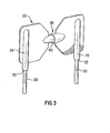
- the inner frame may comprise headrest insert 20, such as shown in Fig. 1 in one preferred embodiment of this invention.
- Headrest insert 20 is preferably at least partially molded from a strong, semi-rigid material such as high density polyethylene (HDPE) or other similar material known to those having ordinary skill in the art. According to one preferred embodiment of this invention, headrest insert 20 forms a generally planar, unitary surface. Cost considerations favor molding a unitary headrest insert 20 thereby eliminating the need for the fitting and assembly of multiple components.
- HDPE high density polyethylene
- Headrest insert 20 preferably includes two receivers 25.
- the receivers 25 preferably accommodate headrest rods 30.
- Each headrest rod 30 preferably includes fixed end 33 positioned within one receiver 25.
- An opposite, moveable end 34 is preferably slideably connected with respect to the seat as described below.
- the two receivers 25 are independently moveable with respect to each other. Independent motion of each receiver 25 preferably permits each headrest rod 30 to find its own center when slideably engaged with respect to the seat. Therefore, if the seat or the headrest is improperly assembled, the headrest will still slide with minimal efforts with respect to the seat.
- headrest insert 20 may comprise at least one transition 35, such as a corrugation, bend or similar such irregular surface molded into an approximate center of headrest insert 20.
- headrest insert 20 may be tapered between the two receivers 25. Headrest insert 20 may include the irregular surface at the maximum taper between the two receivers 25. Alternatively, or in addition, headrest insert 20 may further comprise a reduced thickness between the two receivers 25. The taper, irregular surface, reduced thickness and/or transition 35 results in headrest insert 20 that is flexible about a central area thereby permitting limited independent movement of the two receivers 25 with respect to one another.
- headrest insert 20 further comprises joint 40 positioned between the two receivers 25.
- joint 40 may comprise a ball and socket joint or any other arrangement known to those having ordinary skill in the art that permits more than one axis of rotation between the two receivers 25.
- Headrest having headrest insert 20 as described above may be connected with respect to a conventional seatback assembly having two independent guides positioned within two welded supports on the seat frame. Headrest insert 20 will self-adjust in the instance where the welded supports or the independent guides are misaligned with respect to one another. Alternatively, headrest insert 20 may be used in connection the headrest guide shown in Figs. 4 and 6.
- FIG. 4 and 6 show headrest guide 30 for accepting two headrest rods 30.
- Headrest guide 50 preferably comprises two sleeves 55, each sleeve 55 forming a central channel 57.
- the diameter of central channels 57 preferably approximately correspond with the diameter of headrest rods 30 to permit smooth sliding engagement.
- a plurality of rigid struts 60 preferably extend between the two sleeves 55 so that centerlines of each channel 57 are parallel with respect to one another.
- headrest guide 50 preferably comprises a unitary molded component. Therefore, when one sleeve 55 is misaligned with respect to seat frame 70, the other sleeve 55 is correspondingly misaligned resulting in sleeves 55 aligning with each other.
- the plurality of rigid struts 60 comprise a first horizontal strut 60 positioned between a respective upper region of each sleeve 55 of the two sleeves 55; a second horizontal strut 60 positioned between a respective lower region of each sleeve 55 of the two sleeves 55; and two diagonal struts 60 positioned between the upper region and the lower region of each sleeve 55 of the two sleeves 55.
- This arrangement of struts 60 results in a strong, yet efficient, connection between sleeves 55 in headrest guide 50.
- headrest guide 50 is connected to guide frame 75 that is further positioned within seat frame 70.
- Guide frame 75 is welded or otherwise affixed with respect to seat frame 70.
- Guide frame 75 preferably includes cavity 80 to permit insertion and/or attachment of headrest guide 50 to seat frame 70.
- Headrest guide 50 may be affixed to guide frame 75 with one or more retaining clips 65 positioned with respect to an outer surface of the sleeve 55.
- Headrest guide 50 may additionally comprise receptacle 63 positioned within a top portion of each sleeve 55 for engaging headrest cap 68.
- Headrest cap 68 may be configured to permit fixing the horizontal position of the headrest, such as with a biased latch positioned within notches formed in the headrest rods 30.
Landscapes
- Engineering & Computer Science (AREA)
- Aviation & Aerospace Engineering (AREA)
- Transportation (AREA)
- Mechanical Engineering (AREA)
- Seats For Vehicles (AREA)
- Chair Legs, Seat Parts, And Backrests (AREA)
Abstract
Description
Claims (20)
- A headrest comprising:a headrest insert having two receivers, the two receivers independently moveable with respect to each other;two headrest rods, each headrest rod having a fixed end positioned within a receiver of the two receivers.
- The headrest of Claim 1 wherein the headrest insert further comprises at least one transition molded into an approximate center of the headrest insert.
- The headrest of Claim 1 or 2 wherein the headrest insert forms a generally planar, unitary surface.
- The headrest of Claim 3 wherein the headrest insert further comprises a corrugation positioned along the generally planar, unitary surface.
- The headrest of at least one of the preceding claims wherein the headrest insert further comprises a joint positioned between the two receivers.
- The headrest of at least one of the preceding claims wherein the headrest insert is tapered between the two receivers.
- The headrest of Claim 6 wherein the headrest insert further comprises an irregular surface at a maximum taper between the two receivers.
- The headrest of at least one of the preceding claims wherein the headrest insert comprises a reduced thickness between the two receivers.
- A headrest assembly comprising:a headrest guide having two sleeves, each sleeve forming a channel, the two sleeves rigidly connected with respect to one another so that the channel of each sleeve is parallel with the other;a headrest insert having a flexible coupling; andtwo generally parallel rods, each rod fixed at one end with respect to the headrest insert and slideable at an opposite end with respect to one channel in the headrest guide.
- The headrest assembly of Claim 9 wherein the headrest guide is an integrally molded, unitary component.
- The headrest assembly of Claim 9 wherein the headrest guide is connected with respect to a seat frame of a vehicle.
- The headrest assembly of at least one of claims 9 to 11 wherein the headrest rods are fixed to the headrest insert on opposite sides of the coupling.
- The headrest assembly of at least one of claims 9 to 12 wherein the headrest insert tapers from each outer end toward a center portion.
- A headrest guide for accepting two headrest rods, the headrest guide comprising:two sleeves, each sleeve forming a channel; anda plurality of rigid struts extending between the two sleeves so that centerlines of each channel are parallel with respect to one another.
- The headrest guide of Claim 14 wherein the headrest guide is a unitary molded component.
- The headrest guide of Claim 14 or 15 wherein each sleeve of the two sleeves further includes at least one retaining clip positioned with respect to an outer surface of the sleeve.
- The headrest guide of at least one of claims 14 to 16 wherein each sleeve of the two sleeves further comprises a receptacle positioned within a top portion of the sleeves, the receptacle for engaging a headrest cap.
- The headrest guide of at least one of claims 14 to 17 wherein the plurality of rigid struts comprise:a first horizontal strut positioned between a respective upper region of each sleeve of the two sleeves;a second horizontal strut positioned between a respective lower region of each sleeve of the two sleeves; andtwo diagonal struts positioned between the upper region and the lower region of each sleeve of the two sleeves.
- The headrest guide of at least one of claims 14 to 18 wherein the headrest guide is connected to a guide frame that is further positioned within a seat frame.
- The headrest guide of at least one of claims 14 to 19 wherein the plurality of rigid struts are integrally molded with respect to the two sleeves.
Applications Claiming Priority (2)
| Application Number | Priority Date | Filing Date | Title |
|---|---|---|---|
| US435980 | 1989-11-13 | ||
| US09/435,980 US6224158B1 (en) | 1999-11-08 | 1999-11-08 | Headrest assembly |
Publications (2)
| Publication Number | Publication Date |
|---|---|
| EP1097837A2 true EP1097837A2 (en) | 2001-05-09 |
| EP1097837A3 EP1097837A3 (en) | 2002-02-13 |
Family
ID=23730618
Family Applications (1)
| Application Number | Title | Priority Date | Filing Date |
|---|---|---|---|
| EP00120791A Withdrawn EP1097837A3 (en) | 1999-11-08 | 2000-09-23 | Headrest assembly |
Country Status (3)
| Country | Link |
|---|---|
| US (2) | US6224158B1 (en) |
| EP (1) | EP1097837A3 (en) |
| CA (1) | CA2320658C (en) |
Cited By (4)
| Publication number | Priority date | Publication date | Assignee | Title |
|---|---|---|---|---|
| EP1752334A3 (en) * | 2005-08-12 | 2007-06-06 | Illinois Tool Works Inc. | Headrest insert |
| FR2898558A1 (en) * | 2006-03-14 | 2007-09-21 | Cera | Headrest for motor vehicle, has median part comprising displacement zones arranged so as to permit elastic displacement between upper end parts by manual action, where median part is integrated to cushion |
| FR2944487A1 (en) * | 2009-04-16 | 2010-10-22 | Tachi S Co | Headrest for vehicle seat, has horizontal frame portion, vertical frame portions and impact absorption bar embedded in foam padding filled inside headrest main portion, and headrest stays extended from headrest main portion |
| WO2017005660A1 (en) * | 2015-07-03 | 2017-01-12 | Johnson Controls Gmbh | Headrest body and headrest |
Families Citing this family (20)
| Publication number | Priority date | Publication date | Assignee | Title |
|---|---|---|---|---|
| US6648416B2 (en) * | 1998-08-13 | 2003-11-18 | Richard W. O'Connor | Headrest |
| US20050127734A1 (en) * | 2003-12-16 | 2005-06-16 | Lear Corporation | Energy management head restraint insert |
| US7537282B2 (en) * | 2003-12-16 | 2009-05-26 | Lear Corporation | Head restraint arrangement for a vehicle seat and a method of manufacture |
| US7086701B2 (en) * | 2004-01-13 | 2006-08-08 | Intier Automotive Inc. | Head restraint guide system |
| US6948773B2 (en) * | 2004-02-17 | 2005-09-27 | Lear Corporation | Helical head restraint guide |
| FR2881088B1 (en) * | 2005-01-26 | 2007-04-27 | Itw De France Soc Par Actions | HEADREST FOR A SEAT BACKREST, IN PARTICULAR A VEHICLE |
| DE102005014897B4 (en) * | 2005-04-01 | 2007-11-08 | Keiper Gmbh & Co.Kg | Headrest system for a vehicle seat |
| USD540576S1 (en) | 2005-08-12 | 2007-04-17 | Illinois Tool Works Inc | Headrest insert |
| US7303237B1 (en) * | 2006-03-01 | 2007-12-04 | Derek Hughes | Headrest device, kit and method of using |
| JP5235346B2 (en) * | 2007-07-18 | 2013-07-10 | 日野自動車株式会社 | Vehicle headrest structure |
| JP2009189486A (en) * | 2008-02-13 | 2009-08-27 | Tachi S Co Ltd | Vehicle seat headrest |
| US20100140426A1 (en) * | 2008-12-04 | 2010-06-10 | Corey Aaron Bennett | Vehicle Headrest Accessory Mount |
| US7954899B2 (en) * | 2008-12-22 | 2011-06-07 | Toyota Motor Engineering & Manufacturing North America, Inc. | Seat back assembly with an adjustable headrest |
| DE112011100271B4 (en) | 2010-01-18 | 2014-09-18 | Lear Corporation | seat assembly |
| DE102010023991B4 (en) * | 2010-06-16 | 2022-08-25 | Volkswagen Ag | Plastic backrest of a motor vehicle seat |
| JP6450975B2 (en) * | 2015-05-13 | 2019-01-16 | トヨタ紡織株式会社 | Vehicle seat |
| DE102017117847A1 (en) * | 2017-08-07 | 2019-02-07 | Faurecia Autositze Gmbh | Device and method for adjusting a seat |
| DE102017117846A1 (en) * | 2017-08-07 | 2019-02-07 | Faurecia Autositze Gmbh | Device and method for adjusting a seat |
| US11059406B1 (en) * | 2020-02-21 | 2021-07-13 | GM Global Technology Operations LLC | Head restraint with auxilary power |
| CN216709111U (en) * | 2021-11-25 | 2022-06-10 | 广州荒井汽车零部件有限公司 | Headrest support and seat headrest |
Citations (4)
| Publication number | Priority date | Publication date | Assignee | Title |
|---|---|---|---|---|
| US4779928A (en) | 1986-09-09 | 1988-10-25 | Tamco Limited | Automotive head restraint |
| US5713634A (en) | 1996-09-30 | 1998-02-03 | Koike; Toshihisa | Seat back structure of vehicle seat |
| US5816658A (en) | 1997-05-23 | 1998-10-06 | Flexsteel Industries, Inc. | Head rest lock |
| US5895094A (en) | 1996-04-08 | 1999-04-20 | Aisin Seiki Kabushiki Kaisha | Headrest apparatus for vehicle seat |
Family Cites Families (39)
| Publication number | Priority date | Publication date | Assignee | Title |
|---|---|---|---|---|
| US1949113A (en) * | 1930-11-18 | 1934-02-27 | Charles H Cox | Stadium seat |
| US2020573A (en) | 1934-11-27 | 1935-11-12 | Harry E Pumphrey | Headrest for seat backs |
| US2577050A (en) * | 1947-04-04 | 1951-12-04 | Tracy Henry Van Buren | Resilient back rest for posture chairs |
| CH535141A (en) | 1971-03-08 | 1973-03-31 | Radioelectrique Comp Ind | Neck support |
| JPS5725892Y2 (en) | 1977-12-30 | 1982-06-04 | ||
| US4262918A (en) * | 1979-08-10 | 1981-04-21 | Sandino Hector M | Unitary molded skate chassis |
| US4390209A (en) | 1980-01-25 | 1983-06-28 | Toyo Kogyo Co., Ltd. | Plastic seat-back framework and method for the manufacture thereof |
| JPS60167558U (en) * | 1984-04-13 | 1985-11-07 | アイシン精機株式会社 | Vertically movable headrest device |
| JPH047940Y2 (en) * | 1985-02-27 | 1992-02-28 | ||
| US4657297A (en) | 1985-04-25 | 1987-04-14 | Mazda Motor Corporation | Rear seat apparatus for automobile |
| US4989836A (en) * | 1989-04-04 | 1991-02-05 | Premier Solutions, Ltd. | Detachable wheelchair headrest |
| US5131720A (en) | 1990-09-25 | 1992-07-21 | Tachi-S Co., Ltd. | Headrest device |
| GB2263632B (en) * | 1992-01-16 | 1995-11-01 | Gen Motors Corp | Head restraint |
| US5167205A (en) * | 1992-03-19 | 1992-12-01 | Bell John D | Convertible disposable animal litter container |
| US5348376A (en) | 1992-04-21 | 1994-09-20 | Tachi-S Co., Ltd. | Arrangement of headrest on a seat |
| US5398996A (en) * | 1992-08-12 | 1995-03-21 | Ford Motor Company | Blow-molded headrest armature assembly |
| US5362129A (en) | 1992-09-29 | 1994-11-08 | Tachi-S Co., Ltd. | Structure of a casing for headrest stay |
| US5292208A (en) * | 1992-10-14 | 1994-03-08 | C-Loc Retention Systems, Inc. | Corner adapter for corrugated barriers |
| US5397170A (en) | 1993-09-20 | 1995-03-14 | Shrock Manufacturing, Inc. | Headrest bracket |
| JP3592378B2 (en) | 1994-08-28 | 2004-11-24 | 株式会社イノアックコーポレーション | Headrest and manufacturing method thereof |
| GB2333074B (en) | 1995-02-20 | 1999-08-25 | Autoliv Dev | Improvements in or relating to a safety device |
| DE19512012C2 (en) | 1995-03-31 | 1998-05-07 | Brose Fahrzeugteile | Adjustable, cross-split backrest for a vehicle seat |
| JP3694936B2 (en) | 1995-04-20 | 2005-09-14 | トヨタ紡織株式会社 | Retractable headrest |
| DE19523358C8 (en) | 1995-06-28 | 2006-01-26 | Volkswagen Ag | Locking mechanism for a headrest |
| US5667276A (en) * | 1995-12-29 | 1997-09-16 | Illinois Tool Works Inc. | Locking headrest support assembly |
| US5788250A (en) * | 1996-03-25 | 1998-08-04 | Lear Corporation | Headrest guide sleeve |
| US5769499A (en) | 1996-06-07 | 1998-06-23 | Lear Corporation | Motor vehicle seat |
| IT1284669B1 (en) | 1996-07-16 | 1998-05-21 | Bruzolo Manifatt Gestind Mb | HEADREST FOR VEHICLE SEATS. |
| IT1284673B1 (en) | 1996-07-16 | 1998-05-21 | Bruzolo Manifatt Gestind Mb | HEADREST FOR VEHICLE SEATS. |
| US6007154A (en) * | 1996-09-16 | 1999-12-28 | Illinois Tool Works Inc. | Four-way articulating headrest system for automotive seats |
| US5829832A (en) | 1997-04-07 | 1998-11-03 | Molee; Warren F. | Towel retainer headrest device |
| DE19748594A1 (en) | 1997-11-04 | 1999-05-06 | Bayerische Motoren Werke Ag | Backrest of a motor vehicle seat with a headrest |
| US5904026A (en) | 1997-12-12 | 1999-05-18 | Riverwood International Corporation | Adjustable height flight |
| US5927813A (en) | 1998-02-05 | 1999-07-27 | Tachi-S Co., Ltd. | Arrangement of headrest stay holder and holder bracket in vehicles seat |
| US5967612A (en) * | 1998-06-18 | 1999-10-19 | Tachi-S Co., Ltd. | Headrest for automotive seat |
| US5927814A (en) | 1998-06-18 | 1999-07-27 | Tachi-S Co., Ltd. | Headrest |
| US5904405A (en) | 1998-08-07 | 1999-05-18 | Wu; Frank | Pillow structure for chairs |
| US6062645A (en) * | 1998-12-14 | 2000-05-16 | Del-Met Corporation | Headrest support assembly |
| DE19924236C1 (en) | 1999-05-27 | 2000-10-26 | Ise Gmbh | Active headrest for automobile passenger seat has release system coupled to rear impact sensor for controlled release of mechanical catch allowing headrest to pivot forwards via spring-loaded device |
-
1999
- 1999-11-08 US US09/435,980 patent/US6224158B1/en not_active Expired - Lifetime
-
2000
- 2000-06-16 US US09/595,531 patent/US6789850B1/en not_active Expired - Lifetime
- 2000-09-23 EP EP00120791A patent/EP1097837A3/en not_active Withdrawn
- 2000-09-26 CA CA002320658A patent/CA2320658C/en not_active Expired - Fee Related
Patent Citations (4)
| Publication number | Priority date | Publication date | Assignee | Title |
|---|---|---|---|---|
| US4779928A (en) | 1986-09-09 | 1988-10-25 | Tamco Limited | Automotive head restraint |
| US5895094A (en) | 1996-04-08 | 1999-04-20 | Aisin Seiki Kabushiki Kaisha | Headrest apparatus for vehicle seat |
| US5713634A (en) | 1996-09-30 | 1998-02-03 | Koike; Toshihisa | Seat back structure of vehicle seat |
| US5816658A (en) | 1997-05-23 | 1998-10-06 | Flexsteel Industries, Inc. | Head rest lock |
Cited By (5)
| Publication number | Priority date | Publication date | Assignee | Title |
|---|---|---|---|---|
| EP1752334A3 (en) * | 2005-08-12 | 2007-06-06 | Illinois Tool Works Inc. | Headrest insert |
| FR2898558A1 (en) * | 2006-03-14 | 2007-09-21 | Cera | Headrest for motor vehicle, has median part comprising displacement zones arranged so as to permit elastic displacement between upper end parts by manual action, where median part is integrated to cushion |
| FR2944487A1 (en) * | 2009-04-16 | 2010-10-22 | Tachi S Co | Headrest for vehicle seat, has horizontal frame portion, vertical frame portions and impact absorption bar embedded in foam padding filled inside headrest main portion, and headrest stays extended from headrest main portion |
| WO2017005660A1 (en) * | 2015-07-03 | 2017-01-12 | Johnson Controls Gmbh | Headrest body and headrest |
| US10710484B2 (en) | 2015-07-03 | 2020-07-14 | Adient Luxembourg Holding S.Á R.L. | Headrest body and headrest |
Also Published As
| Publication number | Publication date |
|---|---|
| EP1097837A3 (en) | 2002-02-13 |
| CA2320658A1 (en) | 2001-05-08 |
| US6224158B1 (en) | 2001-05-01 |
| CA2320658C (en) | 2004-05-11 |
| US6789850B1 (en) | 2004-09-14 |
Similar Documents
| Publication | Publication Date | Title |
|---|---|---|
| US6224158B1 (en) | Headrest assembly | |
| EP1690732B1 (en) | Headrest support and locking member | |
| US5860703A (en) | Vehicle seat including a headrest, and a headrest for a vehicle seat | |
| US5906414A (en) | Snap-on, pivotable vehicle headrest assembly | |
| US8820832B2 (en) | Active head restraint with wiring pass-through | |
| CA1270180A (en) | Device for fixing a headrest on a vehicle seat structure | |
| GB2357032A (en) | Headrest guide | |
| US12145479B2 (en) | Seat rail locking device for vehicle | |
| EP1752334B1 (en) | Headrest insert | |
| US6796589B2 (en) | Barrier | |
| CN114633673B (en) | Backrest with a carrier module for a headrest and seat | |
| US20100078983A1 (en) | Support member for vehicle seat head restraint | |
| US20090218874A1 (en) | Headrest for a vehicle seat | |
| US20010026091A1 (en) | Headrest apparatus for vehicle seat | |
| US11396250B2 (en) | Upper seat back assembly | |
| US6655742B1 (en) | Locking/unlocking mechanism for headrest | |
| EP4056417B1 (en) | Sleeve device for a headrest | |
| CN107848452B (en) | Headrest body and headrest | |
| CN210258130U (en) | Automobile central armrest | |
| US20210188143A1 (en) | Vehicle seat assembly with impact energy management | |
| US20180043808A1 (en) | Integrated seat back support member for seat assemblies | |
| US9403457B2 (en) | Headrest, vehicle seat | |
| US20050184572A1 (en) | Tubeless headrest support system | |
| US20210188142A1 (en) | Vehicle seat assembly with impact energy management | |
| KR20190035292A (en) | Controlling apparatus of headrest |
Legal Events
| Date | Code | Title | Description |
|---|---|---|---|
| PUAI | Public reference made under article 153(3) epc to a published international application that has entered the european phase |
Free format text: ORIGINAL CODE: 0009012 |
|
| AK | Designated contracting states |
Kind code of ref document: A2 Designated state(s): AT BE CH CY DE DK ES FI FR GB GR IE IT LI LU MC NL PT SE Kind code of ref document: A2 Designated state(s): DE FR GB IT |
|
| AX | Request for extension of the european patent |
Free format text: AL;LT;LV;MK;RO;SI |
|
| PUAL | Search report despatched |
Free format text: ORIGINAL CODE: 0009013 |
|
| AK | Designated contracting states |
Kind code of ref document: A3 Designated state(s): AT BE CH CY DE DK ES FI FR GB GR IE IT LI LU MC NL PT SE |
|
| AX | Request for extension of the european patent |
Free format text: AL;LT;LV;MK;RO;SI |
|
| 17P | Request for examination filed |
Effective date: 20020315 |
|
| AKX | Designation fees paid |
Free format text: DE FR GB IT |
|
| 17Q | First examination report despatched |
Effective date: 20021018 |
|
| STAA | Information on the status of an ep patent application or granted ep patent |
Free format text: STATUS: THE APPLICATION IS DEEMED TO BE WITHDRAWN |
|
| 18D | Application deemed to be withdrawn |
Effective date: 20030301 |