EP1097735A2 - Entertainment system, entertainment apparatus, recording medium, and program - Google Patents
Entertainment system, entertainment apparatus, recording medium, and program Download PDFInfo
- Publication number
- EP1097735A2 EP1097735A2 EP00309037A EP00309037A EP1097735A2 EP 1097735 A2 EP1097735 A2 EP 1097735A2 EP 00309037 A EP00309037 A EP 00309037A EP 00309037 A EP00309037 A EP 00309037A EP 1097735 A2 EP1097735 A2 EP 1097735A2
- Authority
- EP
- European Patent Office
- Prior art keywords
- audio data
- control
- entertainment apparatus
- control input
- entertainment
- Prior art date
- Legal status (The legal status is an assumption and is not a legal conclusion. Google has not performed a legal analysis and makes no representation as to the accuracy of the status listed.)
- Ceased
Links
Images


Classifications
-
- A—HUMAN NECESSITIES
- A63—SPORTS; GAMES; AMUSEMENTS
- A63F—CARD, BOARD, OR ROULETTE GAMES; INDOOR GAMES USING SMALL MOVING PLAYING BODIES; VIDEO GAMES; GAMES NOT OTHERWISE PROVIDED FOR
- A63F13/00—Video games, i.e. games using an electronically generated display having two or more dimensions
- A63F13/50—Controlling the output signals based on the game progress
- A63F13/54—Controlling the output signals based on the game progress involving acoustic signals, e.g. for simulating revolutions per minute [RPM] dependent engine sounds in a driving game or reverberation against a virtual wall
-
- A63F13/10—
-
- A—HUMAN NECESSITIES
- A63—SPORTS; GAMES; AMUSEMENTS
- A63F—CARD, BOARD, OR ROULETTE GAMES; INDOOR GAMES USING SMALL MOVING PLAYING BODIES; VIDEO GAMES; GAMES NOT OTHERWISE PROVIDED FOR
- A63F13/00—Video games, i.e. games using an electronically generated display having two or more dimensions
- A63F13/45—Controlling the progress of the video game
-
- G—PHYSICS
- G10—MUSICAL INSTRUMENTS; ACOUSTICS
- G10H—ELECTROPHONIC MUSICAL INSTRUMENTS; INSTRUMENTS IN WHICH THE TONES ARE GENERATED BY ELECTROMECHANICAL MEANS OR ELECTRONIC GENERATORS, OR IN WHICH THE TONES ARE SYNTHESISED FROM A DATA STORE
- G10H7/00—Instruments in which the tones are synthesised from a data store, e.g. computer organs
- G10H7/02—Instruments in which the tones are synthesised from a data store, e.g. computer organs in which amplitudes at successive sample points of a tone waveform are stored in one or more memories
-
- A—HUMAN NECESSITIES
- A63—SPORTS; GAMES; AMUSEMENTS
- A63F—CARD, BOARD, OR ROULETTE GAMES; INDOOR GAMES USING SMALL MOVING PLAYING BODIES; VIDEO GAMES; GAMES NOT OTHERWISE PROVIDED FOR
- A63F13/00—Video games, i.e. games using an electronically generated display having two or more dimensions
- A63F13/90—Constructional details or arrangements of video game devices not provided for in groups A63F13/20 or A63F13/25, e.g. housing, wiring, connections or cabinets
- A63F13/95—Storage media specially adapted for storing game information, e.g. video game cartridges
-
- A—HUMAN NECESSITIES
- A63—SPORTS; GAMES; AMUSEMENTS
- A63F—CARD, BOARD, OR ROULETTE GAMES; INDOOR GAMES USING SMALL MOVING PLAYING BODIES; VIDEO GAMES; GAMES NOT OTHERWISE PROVIDED FOR
- A63F2300/00—Features of games using an electronically generated display having two or more dimensions, e.g. on a television screen, showing representations related to the game
- A63F2300/60—Methods for processing data by generating or executing the game program
- A63F2300/6063—Methods for processing data by generating or executing the game program for sound processing
-
- G—PHYSICS
- G10—MUSICAL INSTRUMENTS; ACOUSTICS
- G10H—ELECTROPHONIC MUSICAL INSTRUMENTS; INSTRUMENTS IN WHICH THE TONES ARE GENERATED BY ELECTROMECHANICAL MEANS OR ELECTRONIC GENERATORS, OR IN WHICH THE TONES ARE SYNTHESISED FROM A DATA STORE
- G10H2210/00—Aspects or methods of musical processing having intrinsic musical character, i.e. involving musical theory or musical parameters or relying on musical knowledge, as applied in electrophonic musical tools or instruments
- G10H2210/155—Musical effects
- G10H2210/195—Modulation effects, i.e. smooth non-discontinuous variations over a time interval, e.g. within a note, melody or musical transition, of any sound parameter, e.g. amplitude, pitch, spectral response, playback speed
- G10H2210/235—Flanging or phasing effects, i.e. creating time and frequency dependent constructive and destructive interferences, obtained, e.g. by using swept comb filters or a feedback loop around all-pass filters with gradually changing non-linear phase response or delays
-
- G—PHYSICS
- G10—MUSICAL INSTRUMENTS; ACOUSTICS
- G10H—ELECTROPHONIC MUSICAL INSTRUMENTS; INSTRUMENTS IN WHICH THE TONES ARE GENERATED BY ELECTROMECHANICAL MEANS OR ELECTRONIC GENERATORS, OR IN WHICH THE TONES ARE SYNTHESISED FROM A DATA STORE
- G10H2210/00—Aspects or methods of musical processing having intrinsic musical character, i.e. involving musical theory or musical parameters or relying on musical knowledge, as applied in electrophonic musical tools or instruments
- G10H2210/155—Musical effects
- G10H2210/265—Acoustic effect simulation, i.e. volume, spatial, resonance or reverberation effects added to a musical sound, usually by appropriate filtering or delays
- G10H2210/281—Reverberation or echo
- G10H2210/285—Electromechanical effectors therefor, i.e. using springs or similar electromechanical audio delay units
-
- G—PHYSICS
- G10—MUSICAL INSTRUMENTS; ACOUSTICS
- G10H—ELECTROPHONIC MUSICAL INSTRUMENTS; INSTRUMENTS IN WHICH THE TONES ARE GENERATED BY ELECTROMECHANICAL MEANS OR ELECTRONIC GENERATORS, OR IN WHICH THE TONES ARE SYNTHESISED FROM A DATA STORE
- G10H2250/00—Aspects of algorithms or signal processing methods without intrinsic musical character, yet specifically adapted for or used in electrophonic musical processing
- G10H2250/541—Details of musical waveform synthesis, i.e. audio waveshape processing from individual wavetable samples, independently of their origin or of the sound they represent
- G10H2250/571—Waveform compression, adapted for music synthesisers, sound banks or wavetables
- G10H2250/591—DPCM [delta pulse code modulation]
- G10H2250/595—ADPCM [adaptive differential pulse code modulation]
-
- G—PHYSICS
- G10—MUSICAL INSTRUMENTS; ACOUSTICS
- G10H—ELECTROPHONIC MUSICAL INSTRUMENTS; INSTRUMENTS IN WHICH THE TONES ARE GENERATED BY ELECTROMECHANICAL MEANS OR ELECTRONIC GENERATORS, OR IN WHICH THE TONES ARE SYNTHESISED FROM A DATA STORE
- G10H2250/00—Aspects of algorithms or signal processing methods without intrinsic musical character, yet specifically adapted for or used in electrophonic musical processing
- G10H2250/541—Details of musical waveform synthesis, i.e. audio waveshape processing from individual wavetable samples, independently of their origin or of the sound they represent
- G10H2250/631—Waveform resampling, i.e. sample rate conversion or sample depth conversion
Definitions
- the present invention relates to an entertainment system having at least one manual controller connected to an entertainment apparatus which executes various programs, for entering control requests from the user into the entertainment apparatus, an entertainment apparatus which executes various programs, a recording medium storing a program and data that are used by the entertainment system, and a program itself.
- Some entertainment systems including entertainment apparatus such as video game machines display video game images based on video game data stored in a recording medium such as a CD-ROM or the like on the display screen of a television receiver while allowing the user or game player to play the video game with commands entered via a manual controller.
- entertainment apparatus such as video game machines display video game images based on video game data stored in a recording medium such as a CD-ROM or the like on the display screen of a television receiver while allowing the user or game player to play the video game with commands entered via a manual controller.
- the entertainment apparatus and the manual controller are usually connected to each other by a serial interface.
- the manual controller sends key switch information based on the user's control entries in synchronism with the clock signal.
- vibration generating means for applying vibrations to the user based on a request from an external apparatus such as an entertainment apparatus, for example. While a video game is in progress, the vibration generating means applies various different kinds of vibrations to the user in response to user's different control entries.
- BGM BackGround Music
- audio data supplied from music compact discs (CDs) or via a network can be used as a BGM sound source for video games, then a wide variety of existing music data is made available for use in video games, providing an additional element of interest for video games.
- Embodiments of the present invention seek to provide an entertainment system, an entertainment apparatus, a recording medium, and a program which allow audio data supplied from music CDs or via a network to be used as a BGM sound source for the entertainment apparatus, thus providing an additional element of interest for video games.
- an entertainment system comprising an entertainment apparatus for executing various programs, at least one manual controller for entering control requests from the user into the entertainment apparatus, audio output means for selecting and outputting one of a plurality of sound sources based on a supplied sound output command, a display unit for displaying images outputted from the entertainment apparatus, and audio data processing means for registering extracted one of audio data introduced from an external source as one of the sound sources for the entertainment apparatus.
- an entertainment apparatus for connection to a manual controller for outputting at least a control request from the user, a display unit for displaying images, and audio output means for selecting and outputting one of a plurality of sound sources based on a supplied sound output command, comprising audio data processing means for registering extracted one of audio data introduced from an external source as one of the sound sources.
- a recording medium storing a program and data for use in an entertainment system having an entertainment apparatus for executing various programs, at least one manual controller for entering control requests from the user into the entertainment apparatus, audio output means for selecting and outputting one of a plurality of sound sources based on a supplied sound output command, and a display unit for displaying images outputted from the entertainment apparatus, the program comprising the step of registering extracted one of audio data introduced from an external source as one of the sound sources for the entertainment apparatus.
- a program readable and executable by a computer for use in an entertainment system having an entertainment apparatus for executing various programs, at least one manual controller for entering control requests from the user into the entertainment apparatus, audio output means for selecting and outputting one of a plurality of sound sources based on a supplied sound output command, and a display unit for displaying images outputted from the entertainment apparatus, the program comprising the step of registering extracted one of audio data introduced from an external source as one of the sound sources for the entertainment apparatus.
- audio data introduced from a music CD or via a network can be used as a sound source for the entertainment apparatus, providing an additional element of musical interest to video games that are played back on the entertainment apparatus.
- the audio data processing means or step may comprise audio data extracting means for, or the step of, extracting audio data from the audio data introduced from the external source based on a control input entered from the manual controller, and audio data registering means for, or the step of, registering the extracted audio data as one of the sound sources.
- the audio data processing means or step may comprise trimming means for, or the step of, trimming an excessive portion off the extracted audio data. Since unwanted data can be cut off from the extracted audio data, only impressive audio data can be used as a sound source.
- the audio data processing means or step may comprise effect applying means for, or the step of, applying an effect to the extracted audio data.
- effect applying means for, or the step of, applying an effect to the extracted audio data may comprise effect applying means for, or the step of, applying an effect to the extracted audio data.
- the audio data processing means or step may comprise audio data re-extracting means for, or the step of, re-extracting audio data from the extracted audio data. Consequently, the user can extract only favorite portions from the audio data to which various effects have been applied or the audio data from which unwanted portions have been removed. Therefore, the quality of audio data for use as sound sources can be increased, and the process of extracting audio data is easy.
- the audio data re-extracting means or step may comprise selecting playback means for reproducing the extracted audio data according to a playback attribute selected according to a control input entered from the manual controller. Therefore, the audio data can be varied in various playback modes such as the reverse playback mode and the skipping playback mode, resulting in a variety of sound sources available.
- An entertainment system and an entertainment apparatus according to embodiments of the present invention as applied to a video game apparatus, and a recording medium and a program according to embodiments of the present invention as applied to a recording medium which stores a program and data to be executed by the video game apparatus and a program to be executed by the video game apparatus will be described below with reference to FIGS. 1 through 26.
- an entertainment system 10 basically comprises an entertainment apparatus 12 for executing various programs, a memory card 14 detachably connected to the entertainment apparatus 12, a manual controller 16 detachably connected to the entertainment apparatus 12 by a connector 62, and a display monitor 18 such as a television receiver which is supplied with video and audio output signals from the entertainment apparatus 12.
- the entertainment apparatus 12 reads a program recorded in a mass storage medium such as an optical disk 20 such as a CD-ROM or the like, and executes a game, for example, based on the program depending on commands supplied from the user, e.g., the game player, via the manual controller 16.
- the execution of the game mainly represents controlling the progress of the game by controlling the display of images and the generation of sounds on the display monitor 18 based on manual input actions entered from the manual controller 16 via the connector 62.
- the entertainment apparatus 12 has a substantially flat casing in the shape of a rectangular parallelepiped which houses a disk loading unit 22 disposed centrally for loading an optical disk 20 for supplying an application program and data for a video game or the like.
- the casing supports a reset switch 24 for resetting a program which is being presently executed, a disk control switch 26 for controlling the loading of the optical disk 20, a power supply switch 28, and two slots 30, 32.
- the entertainment apparatus 12 may be supplied with the application program via a communication link, rather than being supplied from the optical disk 20 as the recording medium.
- the slots 30, 32 have respective upper slot units 30B, 32B and respective lower slots units 30A, 32A.
- Two manual controllers 16 may be connected respectively to the lower slots units 30A, 32A, and memory cards 14 or portable information terminals (not shown) having the function of the memory card 14 for storing flags indicative of interim game data may be connected respectively to the upper slots units 30B, 32B.
- the slots 30, 32 (the upper slot units 30B, 32B and the lower slots units 30A, 32A) are asymmetrically shaped to prevent the connectors 62 and the memory cards 14 from being inserted in the wrong direction.
- the manual controller 16 has first and second control pads 34, 36, an L (Left) button 38L, an R (Right) button 38R, a start button 40, and a selection button 42.
- the manual controller 16 also has joysticks 44, 46 for inputting analog control actions, a mode selection switch 48 for selecting control modes of the joysticks 44, 46, and a mode indicator 50 for indicating a selected control mode.
- the mode indicator 50 comprises a light-emitting element such as a light-emitting diode or the like.
- the manual controller 16 has a housing 104 comprising an upper member 100 and a lower member 102 which are mated and joined to each other by fasteners such as screws.
- a pair of left and right grips 106, 108 projects from one side of respective opposite ends of the housing 104.
- the left and right grips 106, 108 are shaped so as to be gripped by the palms of left and right hands of the user or game player when the manual controller 16 is connected to the entertainment apparatus 12 and information retrieval is carried out or the game is played thereby, for example.
- the left and right grips 106, 108 are progressively spaced away from each other toward their distal ends.
- the left and right grips 106, 108 are tapered from their joint with the housing 104 toward their distal ends, and have arcuate outer peripheral surfaces and arcuate distal end surfaces.
- the first control pad 34 is disposed on one end of the housing 104 and comprises a first pressable control member (up button) 110a, a second pressable control member (right button) 110b, a third pressable control member (down button) 110c, and a fourth pressable control member (left button) 110d.
- the first through fourth pressable control members 110a, 110b, 110c, 110d project on an upper surface of the housing 104 and are arranged in a crisscross pattern.
- the first control pad 34 includes switch elements as signal input elements associated respectively with the first through fourth pressable control members 110a, 110b, 110c, 110d.
- the first control pad 34 functions as a directional controller for controlling the direction of movement of a displayed game character, for example.
- the game player selectively presses the first through fourth pressable control members 110a, 110b, 110c, 110d to turn on or off the switch elements associated respectively with the first through fourth pressable control members 110a, 110b, 110c, 110d
- the displayed game character moves in the direction corresponding to the pressed one of the first through fourth pressable control members 110a, 110b, 110c, 110d.
- the second control pad 36 is disposed on the other end of the housing 104 and comprises a first pressable control member ( ⁇ button) 112a, a second pressable control member ( ⁇ button) 112b, a third pressable control member ( ⁇ button) 112c, and a fourth pressable control member ( ⁇ button) 112d.
- the first through fourth pressable control members 112a, 112b, 112c, 112d project on the upper surface of the housing 104 and are arranged in a crisscross pattern.
- the first through fourth pressable control members 112a, 112b, 112c, 112d are constructed as independent members, and associated with respective switch elements disposed in the second control pad 36.
- the second control pad 36 serves as a function setting/performing unit for setting functions for a displayed game character assigned to the pressable control members 112a - 112d or performing functions of a displayed game character when the switch elements associated with the pressable control members 112a - 112d are turned on.
- the L button 38L and the R button 38R are disposed on a side of the housing 104 remote from the left and right grips 106, 108 and positioned respectively at the opposite ends of the housing 104. As shown in FIGS. 2 and 4, the L button 38L has a first left pressable control member (L1 button) 114a and a second left pressable control member (L2 button) 114b, and the R button 38R has a first right pressable control member (R1 button) 116a and second right pressable control member (R2 button) 116b, respectively.
- the L button 38L and the R button 38R have respective switch elements associated respectively with the pressable control members (the L1 button 114a, the L2 button 114b, the R1 button 116a, and the R2 button 116b).
- the L button 38L and the R button 38R serve as respective function setting/performing units for setting functions for a displayed game character assigned to the pressable control members 114a, 114b and 116a, 116b or performing functions of a displayed game character when the switch elements associated with the pressable control members 114a, 114b and 116a, 116b are turned on.
- the manual controller 16 also has first and second analog control pads 118, 120 disposed respectively at confronting corners defined between the housing 104 and the proximal ends of the left and right grips 106, 108 which are joined to the housing 104.
- the first and second analog control pads 118, 120 have the respective joysticks 44, 46 which can be tilted in all directions (360°) about control shafts thereof, and respective signal input elements such as variable resistors or the like which are operable by the respective joysticks 44, 46.
- the control shafts of the left and right joysticks 44, 46 are normally urged to return to their neutral positions by biasing members.
- the left and the right joysticks 44, 46 can be freely tilted in all directions (360°) about the axes of the control shafts.
- the first and second analog control pads 118, 120 can move a displayed game character while rotating the same or while changing its speed, and can make an analog-like action such as to change the form of a displayed character, when the game player manipulates the joysticks 44, 46. Therefore, the first and second analog control pads 118, 120 are used as a control unit for entering command signals for a displayed character to perform the above movement or action.
- the mode selection switch 48 When the mode selection switch 48 is pressed, it can select a control mode for allowing a command signal to be inputted from the first and second analog control pads 118, 120 or a control mode for inhibiting a command signal from being inputted from the first and second analog control pads 118, 120.
- the mode selection switch 48 When the mode selection switch 48 is pressed, the functions of the first through fourth pressable control members 112a, 112b, 112c, 112d of the second control pad 36, and the functions of the pressable control members 114a, 114b and 116a, 116b of the L button 38L and the R button 38R are changed depending on the control mode selected by the pressed mode selection switch 48.
- the mode indicator 50 flickers and changes its indication light.
- the left and right grips 106, 108 projecting from the housing 104 are gripped respectively by the palms of the hands of the game player.
- the housing 104 is not required to be supported by fingers, and the manual controller 16 can be held by the hands while at least six out of the ten fingers of the hands can freely be moved.
- the thumbs Lf1, Rf1 of the left and right hands can extend over the joysticks 44, 46 of the first and second analog control pads 118, 120, the first through fourth pressable control members 110a - 110d of the first control pad 34, and the first through fourth pressable control members 112a - 112d of the second control pad 36, and can selectively press the joysticks 44, 46, the pressable control members 110a - 110d, and the pressable control members 112a - 112d.
- the joysticks 44, 46 of the first and second analog control pads 118, 120 are positioned in confronting relation to the proximal ends of the left and right grips 106, 108 which are joined to the housing 104, when the left and right grips 106, 108 are gripped by the left and right hands, the joysticks 44, 46 are positioned most closely to the thumbs Lf1, Rf1, respectively. Therefore, the joysticks 44, 46 can easily be manipulated by the thumbs Lf1, Rf1.
- the index fingers Lf2, Rf2 and middle fingers Lf3, Rf3 of the left and right hands can extend over positions where they can selectively press the L1 button 114a, L2 button 114b of the L button 38L and R1 button 116a, R2 button 116b of the R button 38R.
- the manual controller 16 has a pair of vibration imparting mechanisms 128L, 128R for imparting vibrations to the user in order for the user to be able to play a highly realistic game.
- the left and right vibration imparting mechanisms 128L, 128R are positioned near the proximal ends of the left and right grips 106, 108 that are held by the hands and fingers when the manual controller 16 is gripped by the user.
- the vibration imparting mechanisms 128R comprises a motor 130R energizable by a vibration generating command supplied from the entertainment apparatus 12, and an eccentric member 134R mounted eccentrically on the drive shaft of the motor 130R.
- the eccentric member 134R comprises a weight in the form of a heavy metal member having a semicircular cross-sectional shape.
- the weight has an off-center hole defined therein in which the drive shaft of the motor 130R is fitted.
- the vibration imparting mechanisms 128L, 128R when the motors 130L, 130R are energized, the drive shafts thereof rotate to cause the eccentric members 134L, 134R to rotate in an eccentric motion for thereby generating vibrations, which are imparted to the left grip 106 and the right grip 108. Then, the vibrations of the left grip 106 and the right grip 108 are applied to the hands and fingers of the user.
- the vibration imparting mechanisms 128L, 128R have the different vibration characteristics.
- the motor 130L of the left vibration imparting mechanism 128L is bigger than the motor 130R of the right vibration mechanism 128R.
- the rotational speed of the motor 130L varies according to a vibration value included in a vibration generating command transmitted from the entertainment apparatus 12. That is, vibrations having different frequencies can be generated depending on the vibration value.
- the vibration frequency of the motor 130L varies in proportion to the vibration value.
- the vibration frequency of the motor 130R of the right vibration mechanism 128R does not vary according to the vibration value included in the vibration generating command.
- the motor 130R of the right vibration mechanism 128R is simply either energized or de-energized according to the vibration value. If the vibration value (logic value) is "1", the motor 130R of the right vibration mechanism 128R is energized. If the vibration value is "0”, the motor 130R of the right vibration mechanism 128R is de-energized. When the motor 130R of the right vibration mechanism 128R is energized, it rotates at a constant speed to generate vibrations at a constant frequency.
- the entertainment apparatus 12 generally comprises a control system 60, a graphic generating system 64 connected to the control system 60 via a system bus 61, a sound generating system 66 connected to the control system 60 via the system bus 61, and an optical disk control system 68 connected to the control system 60 via the system bus 61.
- a communication controller 58 for controlling data to be inputted to and outputted from the manual controller 16 and the memory card 14 is also connected to the control system 60 via the system bus 61.
- the manual controller 16 supplies commands (including control data) from the user via a communication controller 150 (see FIG. 7) of the manual controller 16 and the communication controller 58 to the entertainment apparatus 12.
- the optical disk control system 68 includes an optical disk drive 70 in which the optical disk 20, which may comprise a CD-ROM or the like as a specific example of a recording medium according to an embodiment of the present invention.
- the control system 60 controls motions of characters displayed on the monitor 18 based on a program and data read from the optical disk 20 and commands supplied from the manual controller 16.
- the control system 60 includes a central processing unit (CPU) 72, a peripheral device controller 74 for controlling interrupts and direct memory access (DMA) data transfer, a main memory 76 comprising a random-access memory (RAM), and a read-only memory (ROM) 78 which stores various programs such as an operating system for managing the graphic generating system 64, the sound generating system 66, etc.
- the main memory 76 can store at least a game program that is supplied from the optical disk 20 and executed by the central processing unit 72.
- the CPU 72 controls the entertainment apparatus 12 in its entirety by executing the operating system stored in the ROM 78.
- the CPU 72 comprises a 32-bit RISC-CPU, for example.
- the CPU 72 executes the operating system stored in the ROM 78 to start controlling the graphic generating system 64, the sound generating system 66, etc.
- the CPU 72 When the operating system is executed, the CPU 72 initializes the entertainment apparatus 12 in its entirety for confirming its operation, and thereafter controls the optical disc control system 68 to execute an application program such as a game program recorded in the optical disk 20.
- the CPU 72 controls the graphic generating system 64, the sound generating system 66, etc. depending on commands entered from the user for thereby controlling the display of images and the generation of music sounds and sound effects.
- the graphic generating system 64 comprises a geometry transfer engine (GTE) 80 for performing coordinate transformations and other processing, a graphic processing unit (GPU) 82 for rendering image data according to instructions from the CPU 72, a frame buffer 84 for storing image data rendered by the GPU 82, and an image decoder 86 for decoding image data compressed and encoded by an orthogonal transform such as a discrete cosine transform.
- GTE geometry transfer engine
- GPU graphic processing unit
- frame buffer 84 for storing image data rendered by the GPU 82
- an image decoder 86 for decoding image data compressed and encoded by an orthogonal transform such as a discrete cosine transform.
- the GTE 80 has a parallel arithmetic mechanism for performing a plurality of arithmetic operations parallel to each other, and can perform coordinate transformations and light source calculations, and calculate matrixes or vectors at a high speed in response to a request from the CPU 72.
- the GTE 80 can calculate the coordinates of a maximum of 1.5 million polygons per second for a flat shading process to plot one triangular polygon with one color, for example.
- the entertainment apparatus 12 is able to reduce the burden on the CPU 72 and perform high-speed coordinate calculations.
- the GPU 82 According to an image generating instruction from the CPU 72, the GPU 82 generates and stores the data of a polygon or the like in the frame buffer 84.
- the GPU 82 is capable of generating and storing a maximum of 360 thousand polygons per second.
- the frame buffer 84 comprises a dual-port RAM, and is capable of simultaneously storing image data generated by the GPU 82 or image data transferred from the main memory 76, and reading image data for display.
- the frame buffer 84 has a storage capacity of 1 Mbytes, for example, and is handled as a 16-bit matrix made up of a horizontal row of 1024 pixels and a vertical column of 512 pixels.
- the frame buffer 84 has a display area for storing image data to be outputted as video output data, a CLUT (color look-up table) area for storing a color look-up table which will be referred to by the GPU 82 when it renders a polygon or the like, and a texture area for storing texture data to be subjected to coordinate transformations when a polygon is generated and mapped onto a polygon generated by the GPU 82.
- CLUT color look-up table
- the CLUT area and the texture area are dynamically varied as the display area is varied.
- the GPU 82 can perform, in addition to the flat shading process, a Gouraud shading process for determining colors in polygons by interpolating intensities from the vertices of the polygons, and a texture mapping process for mapping textures stored in the texture area onto polygons.
- a Gouraud shading process for determining colors in polygons by interpolating intensities from the vertices of the polygons
- a texture mapping process for mapping textures stored in the texture area onto polygons.
- the GTE 80 can perform coordinate calculations for a maximum of about 500,000 polygons per second.
- the image decoder 86 is controlled by the CPU 72 to decode image data of a still or moving image stored in the main memory 76, and store the decoded image into the main memory 76.
- Image data reproduced by the image decoder 86 is transferred to the frame buffer 84 by the GPU 82, and can be used as a background for an image plotted by the GPU 82.
- the sound generating system 66 comprises a sound processing unit (SPU) 88 for generating music sounds, sound effects, etc. based on instructions from the CPU 72, and a sound buffer 90 for storing music sounds, sound effects, etc. generated by the SPU 88. Audio signals representing music sounds, sound effects, etc. generated by the SPU 88 are supplied to audio terminals of the monitor 18.
- the monitor 18 has a speaker 92 which radiates music sounds, sound effects, etc. generated by the SPU 88 based on the supplied audio signals.
- the SPU 88 has an ADPCM (adaptive differential PCM) function for reproducing 16-bit audio data which has been encoded as 4-bit differential audio data by ADPCM, a reproducing function for reproducing waveform data stored in the sound buffer 90 to generate sound effects, etc., and a modulating function for modulating and reproducing the waveform data stored in the sound buffer 90.
- ADPCM adaptive differential PCM
- the sound system 66 with these functions can be used as a sampling sound source which generates music sounds, sound effects, etc. based on the waveform data stored in the sound buffer 90 according to instructions from the CPU 72.
- the optical disk control system 68 comprises an optical disk drive 70 for reproducing application programs and data recorded on the optical disk 20, a decoder 94 for decoding programs and data that are recorded with an error correcting code added thereto, and a buffer 96 for temporarily storing data read from the optical disk drive 70 so as to allow the data from the optical disk 20 to be read at a high speed.
- An auxiliary CPU 98 is connected to the decoder 94.
- Audio data recorded on the optical disk 20 which is read by the optical disk drive 70 includes PCM data converted from audio signals, in addition to the ADPCM data.
- the ADPCM data which is recorded as 4-bit differential data of 16-bit digital data, is decoded by the decoder 94, supplied to the SPU 88, converted thereby into audio signals, and applied to drive the speaker 92.
- the PCM data which is recorded as 16-bit digital data, is decoded by the decoder 94 and then applied to drive the speaker 92.
- the manual controller 16 comprises a communication controller 150, a CPU 152, a program memory 154, a working RAM 156, a digital input block 158, an analog input block 160, a left motor driver 170L for energizing the left motor 130L, and a right motor driver 170R for energizing the right motor 130R. These components of the communication controller 16 are connected to a bus 162.
- the digital input block 158 functions as a manual input controller for the pressable control members 110a - 110d of the first control pad 34 and the pressable control members 112a - 112d of the second control pad 36.
- the analog input block 160 functions as a manual input controller for the left and right joysticks 44, 46.
- the digital input block 158 and the analog input block 160 allow the user to enter various items of information into the manual controller 16.
- the communication controller 150 has a function to effect serial communications with an external device.
- the communication controller 150 is electrically connectable to the communication controller 58 (see FIG. 6) of the entertainment apparatus 12, for example, for data communications with the entertainment apparatus 12.
- the bidirectional communication function between the entertainment apparatus 12 and the manual controller 16 can be performed when the connector 62 capable of performing bidirectional serial communications with the manual controller 16 is connected to the entertainment apparatus 12.
- a system in the manual controller 16 for performing the bidirectional communication function comprises a serial I/O interface SIO for performing serial communication with the entertainment apparatus 12, a parallel I/O interface PIO for entering control data from a plurality of control buttons, a one-chip microcomputer comprising a CPU, a RAM, and a ROM, and a pair of motor drivers 170R, 170L for energizing the motors 130R, 130L of the vibration imparting mechanisms 128R, 128L.
- Each of the motors 130R, 130L is energized by a voltage and a current supplied from the motor drivers 170R, 170L.
- a system in the entertainment apparatus 12 for performing the bidirectional communication function comprises a serial I/O interface SIO for performing serial communication with the manual controller 16.
- the serial I/O interface SIO of the entertainment apparatus 12 is connected to the serial I/O interface SIO of the manual controller 16 via the connector 62 for performing bidirectional communications between the entertainment apparatus 12 and the manual controller 16.
- Other detailed structure of the entertainment apparatus 12 are omitted from illustration in FIG. 8.
- Signal and control lines for bidirectional serial communications include a data transfer signal line TXD (Transmit X' for Data) for sending data from the entertainment apparatus 12 to the manual controller 16, a data transfer signal line RXD (Received X' for Data) for sending data from the manual controller 16 to the entertainment apparatus 12, a serial synchronous clock signal line SCK (Serial Clock) for extracting data from the data transfer signal lines TXD, RXD, a control line DTR (Data Terminal Ready) for establishing and cutting off communication with the manual controller 16 as a terminal, and a flow control line DSR (Data Set Ready) for transferring a large amount of data.
- TXD Transmit X' for Data
- RXD Receiveived X' for Data
- SCK Serial Clock
- DTR Data Terminal Ready
- DSR Data Set Ready
- the signal and control lines for bidirectional serial communication are accommodated in a cable.
- This cable further includes a power line 172 extending from a power supply in the entertainment apparatus 12 and connected to the motor drivers 170R, 170L in the manual controller 16 for supply electric energy to energize the motors 130R, 130L.
- a process of bidirectional serial communication between the entertainment apparatus 12 and the manual controller 16 will be described below.
- the entertainment apparatus 12 In order for the entertainment apparatus 12 to communicate with the manual controller 16 to read control data from the digital input block 158 and the analog input block 160, the entertainment apparatus 12 first outputs selection data to the control line DTR. As a result, the manual controller 16 confirms that it is selected by the control line DTR, and then waits for a signal from the signal line TXD. Then, the entertainment apparatus 12 outputs an identification code indicative of the manual controller 16 to the data transfer signal line TXD. The manual controller 16 receives the identification code from the signal line TXD.
- the manual controller 16 When the manual controller 16 recognizes the identification code, the manual controller 16 starts communicating with the entertainment apparatus 12.
- the entertainment apparatus 12 sends control data via the data transfer signal line TXD to the manual controller 16, which sends control data from the digital input block 158 and the analog input block 160 via the data transfer signal line RXD to the entertainment apparatus 12.
- the entertainment apparatus 12 and the manual controller 16 perform bidirectional serial communications.
- the bidirectional serial communications will be finished when the entertainment apparatus 12 outputs selection stop data via the control line DTR.
- the manual controller 16 can send mainly control data from the digital input block 158 and the analog input block 160 to the entertainment apparatus 12, and the entertainment apparatus 12 can send vibration generating commands for energizing the motors 130R, 130L of the vibration imparting mechanisms 128R, 128L via the data transfer signal line TXD to the manual controller 16.
- the vibration generating commands for energizing the motors 130R, 130L include those which have been established in advance in the optical disk 20 set in the entertainment apparatus 12 and those which are newly generated in the entertainment apparatus 12.
- a characteristic function of the entertainment system 10 according to the present embodiment will be described below with reference to FIGS. 9 through 26.
- audio data extracted from audio data introduced from an external source is registered as one of sound sources for the entertainment apparatus 12.
- audio data from the optical disk 20 loaded in the optical disk drive 70 of the entertainment apparatus 12 or a network connected to the entertainment apparatus 12 is introduced, and desired audio data is extracted from the introduced audio data and used as a sound source for the entertainment apparatus 12.
- audio data is introduced from a music CD (Compact Disc) loaded in the optical disk drive 70.
- the software comprises a audio data processing means 200.
- the audio data processing means 200 can be supplied to the entertainment system 10 from a randomly accessible recording medium such as a CD-ROM, the memory card 14, or a network. It is assumed in the present embodiment that the audio data processing means 200 is read from the optical disk 20 such as a CD-ROM into the entertainment apparatus 12.
- the audio data processing means 200 is downloaded in advance from the optical disk 20 played back by the entertainment apparatus 12 into the main memory 76 in the control system 60 thereof according to a predetermined process, and executed by the CPU 72 of the control system 60.
- the audio data processing means 200 has a CD checking means 202 for checking whether the optical disk 20 loaded in the optical disk drive 70 is a music CD or not, and a sampling means 204 for sampling any desired music data from audio data introduced when a music CD is played back.
- the sampling means 204 comprises a CD controlling means 210 for controlling the optical disk drive 70 to play, stop, access tracks (forward and backward) of, and otherwise operate a music CD loaded in the optical disk drive 70 in response to control inputs from the manual controller 16, an effect applying means 212 for applying various effects to reproduced music data from the music CD in response to control inputs from the manual controller 16, a parameter changing means 214 for changing parameters including an effect level, a sound volume, etc.
- a sound sampling means 216 for sampling audio data of a portion of the reproduced audio data which is determined by a control input from the manual controller 16 and registering the sampled audio data in a predetermined recording time slot
- a slot selecting means 218 for selecting a recording slot to register sampled audio data therein
- a first command selecting means 220 for selecting various commands after music data is sampled.
- the effect applying means 212 controls the optical disk drive 70 to apply a necessary effect to reproduced audio data.
- the first command selecting means 220 comprises a waveform editing means 222 for removing excessive data from sampled audio data, a re-sampling means 224 for re-sampling desired audio data from sampled audio data, and a sampled data registering means 226 for registering sampled audio data in a audio data file in the sound buffer 90.
- a number of audio data registered in the audio data file serve as sound source data for use by the entertainment apparatus 12.
- the sampled audio data is available as a sound source for the entertainment apparatus 12.
- the sound sampling means 216 uses a recording slot file 228 which has six records corresponding to respective six recording slots, for example, that are handled by the sound sampling means 216. Each of the six records of the recording slot file 228 stores sampled audio data.
- the re-sampling means 224 comprises a slot assigning means 240 for selecting a recording slot to be assigned to a playback time slot (playback slot) for re-sampling, a playback processing means 242 for reproducing audio data assigned to playback slots, a slot selecting means 244 for selecting a playback slot to be played back, an effect applying means 246 for applying various effects to reproduced audio data in response to control inputs from the manual controller 16, a parameter changing means 248 for changing parameters including an effect level, a sound volume, etc.
- a selecting playback means 250 for selecting playback attributes according to control inputs
- a sound re-sampling means 252 for re-sampling audio data of a portion of the reproduced audio data which is determined by a control input from the manual controller 16 and registering the re-sampled audio data in a predetermined playback slot
- a second command selecting means 254 for selecting various commands after audio data is re-sampled.
- the second command selecting means 254 comprises the waveform editing means 222 (see FIG. 9) which removes excessive data from sampled audio data assigned to a selected playback slot, and re-sampled data registering means 256 for registering re-sampled audio data in the audio data file in the sound buffer 90.
- the sound re-sampling means 252 uses a playback slot file 258 which has four records corresponding to respective four playback slots, for example, that are handled by the sound sampling means 252.
- Each of the four records of the playback slot file 258 stores audio data in a selected recording slot.
- the fourth record corresponding to the fourth playback slot stores re-sampled audio data.
- a processing sequence of the audio data processing means 200 will be described below with reference to FIGS. 9, 10, 11 through 23, and through 24 through 26.
- step S1 shown in FIG. 11 the CD checking means 202 displays a message prompting the user to load a music CD in the optical disk drive 70 on the display monitor 18.
- step S2 the CD checking means 202 waits for an optical disk 20 to be loaded. If an optical disk 20 is loaded in the optical disk drive 70, then control goes to step S3 in which the CD checking means 202 checks the loaded optical disk 20.
- step S4 the CD checking means 202 checks if the loaded optical disk 20 is a music CD or not. If the loaded optical disk 20 is not a music CD, then control goes back to step S1, displaying a message prompting the user to load a music CD in the optical disk drive 70 on the display monitor 18. If the loaded optical disk 20 is a music CD, then control proceeds to step S5 in which the sampling means 204 performs its own processing sequence.
- sampling means 204 The processing sequence of the sampling means 204 will be described below with reference to FIGS. 12 and 13.
- the sampling means 204 displays a sampling view 300 (see FIG. 24) on the display monitor 18.
- the sampling view 300 has a playback state display area 302 indicative of playback states, such as a playback track and a playback time, of the music CD, an operation display area 304 for applying an effect, changing parameters, and controlling the music CD, a waveform display area 306 for displaying a registration destination (recording slot) for sampled audio data and also displaying the waveform of sampled audio data, and a time display area 308 for displaying a bar representing a sampling time of audio data.
- a playback state display area 302 indicative of playback states, such as a playback track and a playback time, of the music CD
- an operation display area 304 for applying an effect, changing parameters, and controlling the music CD
- a waveform display area 306 for displaying a registration destination (recording slot) for sampled audio data and also displaying the waveform of sampled audio data
- a time display area 308 for displaying
- the operation display area 304 has an effect selecting area 310 for selecting various effects, a parameter changing area 312 for changing various parameters, and a CD control area 314 for controlling a CD.
- the effects include a type (THRU) for playing back audio data without any effect applied, a type (ECHO) for applying an echo effect to audio data, a type (SPRING) for reverberating audio data using a spring, a type (FLANGER) for applying a flanger to audio data, etc.
- THRU type for playing back audio data without any effect applied
- ECHO type for applying an echo effect to audio data
- SPRING type for reverberating audio data using a spring
- FLANGER for applying a flanger to audio data, etc.
- the user can select any on of the effects with the left button 110d and the right button 110b.
- the parameters include an effect level (depth: EFX), a sound pitch (PIT), and a sound volume (VOL).
- depth: EFX an effect level
- PIT a sound pitch
- VOL a sound volume
- the CD control area 314 displays icons for playing, stopping, accessing tracks (forward) of, and accessing tracks (backward) of, a CD.
- the user can select any one of these icons with the up button 110a, the down button 110c, the left button 110d, and the right button 110b.
- step S102 shown in FIG. 12 the sampling means 204 waits for a control input from the manual controller 16. If there is a control input from the manual controller 16, control goes to step S103 in which the sampling means 204 determines whether the control input is a control input relative to the control of the CD or not. If the control input is a control input relative to the control of the CD, then control goes to step S104 in which the CD controlling means 210 controls the CD according to the control input. Specifically, the CD controlling means 210 plays back the CD, stops the CD, accesses a track on the CD in a forward direction, or accesses a track on the CD in a backward direction.
- control goes to step S105 in which the sampling means 204 determines whether the control input is a control input relative to sampling, e.g., a control input from the start button 40, or not. If the control input is a control input relative to sampling, then the sound sampling means 216 performs its own processing sequence.
- step S201 shown in FIG. 14 the sound sampling means 216 determines whether a music CD is being played back or not. If a music CD is being played back, then control goes to step S202 in which a sampling process is prepared. At this time, the color of the displayed frame of the waveform display area 306 changes to yellow, for example, letting the user know that a sampling process is being prepared.
- step S203 the sound sampling means 216 waits for a control input from the button 112d, serving as a decision button, of the manual controller 16. If there is a control input from the decision button 112d, then control goes to step S204 in which the sound sampling means 216 starts sampling audio data that is being reproduced.
- step S205 the sound sampling means 216 waits for a control input from the decision button 112d. If there is a control input from the decision button 112d, then control goes to step S206 in which the sound sampling means 216 finishes the sampling process.
- step S207 the sound sampling means 216 registers sampled audio data in a record corresponding to a recording slot being selected, of the records in the recording slot file 228.
- step S207 After step S207 or if a music CD is not being played back in step S201, the processing sequence of the sound sampling means 216 is finished.
- Control then goes back to the routine shown in FIG. 12. If the control input is not a control input relative to sampling in step S105, then control goes to step S107 in which the sampling means 204 determines whether the control input is a control input relative to an effect or not. If the control input is a control input relative to an effect, then the effect applying means 212 performs its own processing sequence. Specifically, the user selects an effect with a control input in step S108, and the effect applying means 212 applies the selected effect to audio data being reproduced by the optical disk drive 70 in step S109.
- control goes to step S110 in which the sampling means 204 determines whether the control input is a control input relative to the changing of a parameter or not. If the control input is a control input relative to the changing of a parameter, then the parameter changing means 214 performs its own processing sequence. Specifically, the user selects a parameter with a control input in step S111, and then the parameter changing means 214 changes the numerical value of the selected parameter in step S112. Thereafter, in step S113, audio data is reproduced according to the changed parameter.
- control input is not a control input relative to the changing of a parameter in step S110, then control goes to step S114 shown in FIG. 13 in which the sampling means 204 determines whether the control input is a control input relative to the selection of a slot, e.g., a control input from the R2 button 116b, or not.
- control input is a control input relative to the selection of a slot
- control goes to step S115 in which the slot selecting means 218 performs its own processing sequence.
- step S301 shown FIG. 15 the slot selecting means 218 displays a slot selection view (window view), not shown, on the display monitor 18.
- step S302 the user selects a recording slot in which to register sampled audio data by pressing the up button 110a, the down button 110c, and the decision button 112d of the manual controller 16. Specifically, when the user presses the up button 110a and the down button 110c, a cursor is moved, and when the user presses the decision button 112d, a recording slot where the cursor is positioned is selected. Then, when the user presses the ⁇ button 112c, the selected recording slot is decided.
- step S303 the slot selecting means 218 determines whether the selected recording slot is decided or not. If the selected recording slot is not decided, control goes back to step S302 to select a recording slot again. If the selected recording slot is decided, then control goes to step S304 in which the slot selecting means 218 turns off the slot selection view. The processing sequence of the slot selecting means 218 now comes to an end.
- Control then goes back to the routine shown in FIG. 13.
- step S114 if the control input is not a control input relative to the selection of a slot, then control goes to step S116 in which the sampling means 204 determines whether the control input is a control input relative to the selection of a command, e.g., a control input from the selection button 42, or not.
- control input is a control input relative to the selection of a command
- control goes to step S117 in which the first command selecting means 220 performs its own processing sequence.
- the processing sequence of the first command selecting means 220 will be described below with reference to FIG. 16.
- the first command selecting means 220 displays a command request view, not shown, on the display monitor 18.
- the command request view comprises a window view with an array of three commands including a mode changing command (MODE CHANGE), a waveform editing command (WAVE EDIT), and an end command (EXIT).
- step S402 the user selects a command by pressing the left button 110d, the right button 110b, and the decision button 112d of the manual controller 16.
- step S403 the first command selecting means 220 determines whether the selected command is decided or not. If the selected command is not decided, control goes back to step S402 to select a command again. If the selected command is decided, then control goes to step S404 in which the first command selecting means 220 determines whether the selected command is a command for editing a waveform. If the selected command is a command for editing a waveform, then control goes to step S405 in which the waveform editing means 222 performs its own processing sequence.
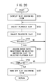
- step S501 shown in FIG. 17 the waveform editing means 222 displays a waveform editing view 320 (see FIG. 25) on the display monitor 18.
- the waveform editing view 320 is a window view having a waveform display area 322 for displaying the waveform of sampled audio data.
- the user can trim front and rear portions on a time axis of the displayed waveform. Specifically, the user presses the down button 110c to place a cursor 324 in the front or rear portion of the displayed waveform, and then presses the left button 110d or the right button 110b to decides a region (time width) to be trimmed off the displayed waveform. After having decided the region to be trimmed off the displayed waveform, the user presses the decision button 112d to trim the region off the displayed waveform.
- step S502 shown in FIG. 17 the waveform editing means 222 displays the waveform of an audio data registered in a selected recording slot in the waveform display area 322.
- step S503 the user decides a region to be trimmed off the displayed waveform in the manner described above. Thereafter, the waveform editing means 222 determines whether the region to be trimmed has been decided or not in step S504. If not decided, then control goes back to step S503 for the user to decide a region to be trimmed off the displayed waveform again.
- control goes to step S505 in which the waveform editing means 222 removes, i.e., trims the selected region off the displayed waveform.
- step S506 the waveform editing means 222 re-registers the trimmed audio data in the selected recording slot. That it, the waveform editing means 222 re-registers the trimmed audio data in a record corresponding to the selected recording slot, of the records in the recording slot file.
- step S507 the waveform editing means 222 determines whether the trimming process has been completed or not based on whether there is a control input from the ⁇ button 112c, for example, or not.
- step S503 If the trimming process has not been completed, then control goes back to step S503 to select a region to be trimmed again. If the trimming process has been completed, then control goes to step S508 in which the waveform editing means 222 turns off the waveform editing view 320. The processing sequence of the waveform editing means 222 is finished.
- Control then returns to the routine shown in FIG. 16. If the selected command is a not command for editing a waveform in step S404 shown in FIG. 16, then control goes to step S406 in which the first command selecting means 220 determines whether the selected command is a command for re-sampling or not. If the selected command is a command for re-sampling, then control goes to step S407 in which the re-sampling means 224 performs its own processing sequence. The processing sequence of the re-sampling means 224 will be described later on.
- step S408 If the selected command is not a command for re-sampling in step S406, then control goes to step S408 in which the sampled data registering means 226 registers the sampled audio data which has been registered in the selected recording slot, in the audio data file, e.g., a user audio data file, in the sound buffer 90. At this time, the audio data becomes available for use as one sound source for the entertainment apparatus 12.
- the processing sequence of the sampling means 204 is ended.
- Control then returns to the routine shown in FIG. 13. If the control input is not a control input relative to the selection of a command in step S116, then control goes to step S118 in which the sampling means 204 determines whether the control input is a control input relative to the changing of a CD or not based on whether the control input is a control input from the R1 button 116a or not.
- control input is a control input relative to the changing of a CD
- control goes back to step S1 shown in FIG. 11 to display a message prompting the user to change a CD in the optical disk drive 70 on the display monitor 18 and wait for a CD to be changed.
- the user can leave this waiting state by pressing the ⁇ button 112c.
- control input is not a control input relative to the changing of a CD in step S118 shown in FIG. 13, then control goes to step S119 in which another process depending on the control input is carried out.
- the re-sampling means 224 displays a re-sampling view 330 (see FIG. 26) on the display monitor 18.
- the re-sampling view 330 has a first slot display area 332 for displaying three selected recording slots, a second slot display area 334 for displaying the recording slot of re-sampled audio data, a playback attribute display area 336 for applying an effect, changing parameters, and selecting playback attributes, and a time display area 350 for displaying a bar representing a re-sampling time of audio data.
- the playback attribute display area 336 has an effect selecting area 338 for selecting various effects, a parameter changing area 340 for changing various parameters, and a playback attribute selecting area 342 for selecting playback attributes.
- the effect selecting area 338 and the parameter changing area 340 are the same as the effect selecting area 310 and the parameter changing area 312 in the sampling view 300 shown in FIG. 24, and will not be described below.
- the playback attribute selecting area 342 allows the user to select a playback direction and playback attributes. The user can select playback attributes by pressing the left button 110d and the right button 110b.
- the playback attributes that can be selected include a reverse playback mode (REVERSE), a skipping playback mode (SKIP), and a scratch playback mode (SCRATCH).
- step S602 shown in FIG. 18, the re-sampling means 224 waits for a control input from the manual controller 16. If there is a control input from the manual controller 16, control goes to step S603 in which the re-sampling means 224 determines whether the control input is a control input relative to the assignment of a slot, e.g., a control input from the R2 button 116b, or not. If the control input is a control input relative to the assignment of a slot, then control goes to step S604 in which the slot assigning means 240 performs its own processing sequence.
- the slot assigning means 240 displays a slot assigning view, not shown, which comprises a window view having a playback slot display area for displaying four playback slots and a recording slot display area for displaying six recording slots.
- step S702 the user selects a playback slot by pressing the L1 button 114a and the L2 button 114b. Then, in step S703, the user selects a recording slot by pressing the up button 110a and the down button 110c.
- step S704 the slot assigning means 240 determines whether the selected slots have been decided or not based on whether there is a control input from the decision button 112d or not. If the selected slots have not been decided, then control goes back to step S702 for the user to select a playback slot and a recording slot again.
- step S705 the slot assigning means 240 assigns the audio data registered in the selected recording slot to the selected playback slot.
- the audio data registered in the second recording slot is assigned to the first playback slot
- the audio data registered in the third recording slot is assigned to the second playback slot
- the audio data registered in the fourth recording slot is assigned to the third playback slot
- the audio data registered in the sixth recording slot is assigned to the fourth playback slot.
- step 706 the slot assigning means 240 determines whether the assignment of a slot has been completed or not based on whether there is a control input from the ⁇ button 112c or not. If the assignment of a slot has not been completed, then control goes back to step S702 to assign a slot again. If the assignment of a slot has been completed, then control goes to step S707 in which the slot assigning means 240 turns off the slot assigning view. The processing sequence of the slot assigning means 240 now comes to an end.
- Control then returns to the routine shown in FIG. 18. If the control input is not a control input relative to the assignment of a slot in step S603, then the re-sampling means 224 determines whether the control input is a control input relative to a playback process, i.e., a control input from the ⁇ button 112a, the ⁇ button 112b, the ⁇ button 112c, or the decision button 112d, or not in step S605.
- a control input relative to a playback process i.e., a control input from the ⁇ button 112a, the ⁇ button 112b, the ⁇ button 112c, or the decision button 112d, or not in step S605.
- control input is a control input relative to a playback process
- control goes to step S606 in which the playback processing means 242 performs its own processing sequence.
- the processing sequence of the playback processing means 242 will be described below with reference to FIG. 21.
- step S801 shown in FIG. 21 the playback processing means 242 reproduces audio data in a playback slot depending on the control input. Specifically, if the control input comes from the ⁇ button 112a, then the playback processing means 242 reproduces audio data in the first playback slot. If the control input comes from the ⁇ button 112b, then the playback processing means 242 reproduces audio data in the second playback slot. If the control input comes from the ⁇ button 112c, then the playback processing means 242 reproduces audio data in the third playback slot. If the control input comes from the decision button 112d, then the playback processing means 242 reproduces audio data in the fourth playback slot.
- step S802 the playback processing means 242 determines whether there is a control input indicative of a playback hold mode, e.g., a control input from the R1 button 116a, or not. If there is a control input indicative of a playback hold mode, then control goes to step S803 in which the playback processing means 242 holds the playback of the audio data assigned to the selected playback slot.
- a control input indicative of a playback hold mode e.g., a control input from the R1 button 116a
- step S804 If there is not a control input indicative of a playback hold mode in step S802, then control goes to step S804 in which the playback processing means 242 waits for a control input to end. If a control input comes to an end, then control goes to step S805 to finish the playback process.
- step S803 or step S805 the processing sequence of the playback processing means 242 is brought to an end.
- control returns to the routine shown in FIG. 18. If the control input is no a control input relative to a playback process in step S605, then control goes to step S607 in which the re-sampling means 224 determines whether the control input is a control input relative to re-sampling or not. If the control input is a control input relative to re-sampling, then control goes to step S608 in which the sound re-sampling means 252 performs its own processing sequence. The processing sequence of the sound re-sampling means 252 will be described later on.
- control goes to step S609 in which the re-sampling means 224 determines whether the control input is a control input relative to an effect or not. If the control input is a control input relative to an effect, then the effect applying means 246 performs its own processing sequence. Specifically, the user selects an effect with a control input in step S610, and the effect applying means 246 applies the selected effect to audio data being reproduced by the optical disk drive 70 in step S611.
- step S609 if the control input is not a control input relative to an effect, then control goes to step S612 (see FIG. 19) in which the re-sampling means 224 determines whether the control input is a control input relative to the changing of a parameter or not. If the control input is a control input relative to the changing of a parameter, then the parameter changing means 248 performs its own processing sequence. Specifically, the user selects a parameter with a control input in step S613, and then the parameter changing means 248 changes the numerical value of the selected parameter in step S614. Thereafter, in step S615, audio data is reproduced according to the changed parameter.
- control goes to step S616 in which the re-sampling means 224 determines whether the control input is a control input relative to the selection of a playback attribute or not. If the control input is a control input relative to the selection of a playback attribute, then the selecting playback means 250 performs its own processing sequence. Specifically, the user selects a playback attribute with a control input in step S617, and the selecting playback means 250 reproduces audio data according to the selected playback attribute in step S618.
- control goes to step S619 in which the re-sampling means 224 determines whether the control input is a control input relative to the selection of a slot.
- a slot can be selected with the L1 button 114a and the L2 button 114b, for example.
- control input is a control input relative to the selection of a slot
- control goes to step S620 in which the slot selecting means 244 selects a playback slot to be played back according to a control input.
- step S608 The processing sequence of the sound re-sampling means 252 in step S608 will be described below with reference to FIG. 22.
- step S901 shown in FIG. 22 the sound re-sampling means 252 determines whether audio data is being reproduced or not. If audio data is being reproduced, then control goes to step S902 in which a re-sampling process is prepared. At this time, the color of the displayed frame of the second slot display area 334 changes to yellow, for example, letting the user know that a re-sampling process is being prepared.
- step S903 the sound re-sampling means 252 waits for a control input from the decision button 112d. If there is a control input from the decision button 112d, then control goes to step S904 in which the sound re-sampling means 252 starts re-sampling audio data that is being reproduced.
- step S905 the sound re-sampling means 252 waits for a control input from the decision button 112d. If there is a control input from the decision button 112d, then control goes to step S906 in which the sound re-sampling means 252 finishes the re-sampling process.
- step S907 the sound re-sampling means 252 registers re-sampled audio data in the fourth playback slot, i.e., in a record corresponding to the fourth playback slot, of the records in the playback slot file 258.
- step S907 After step S907 or if audio data is not being reproduced in step S901, the processing sequence of the sound re-sampling means 252 is finished.
- Control then goes back to the routine shown in FIG. 19. If the control input is not a control input relative to the selection of a slot in step S619, then control goes to step S621 in which the sound re-sampling means 252 determines whether the control input is a control input relative to the selection of a command, e.g., a control input from the selection button 42, or not.
- control input is a control input relative to the selection of a command
- control goes to step S622 in which the second command selecting means 254 performs its own processing sequence.
- the second command selecting means 254 displays a command request view, not shown, on the display monitor 18.
- the command request view comprises a window view with an array of three commands including a mode changing command (MODE_CHANGE), a waveform editing command (WAVE_EDIT), and an end command (EXIT).
- step S1002 the user selects a command by pressing the left button 110d, the right button 110b, and the decision button 112d of the manual controller 16.
- step S1003 the second command selecting means 254 determines whether the selected command is decided or not. If the selected command is not decided, control goes back to step S1002 to select a command again. If the selected command is decided, then control goes to step S1004 in which the second command selecting means 254 determines whether the selected command is a command for editing a waveform. If the selected command is a command for editing a waveform, then control goes to step S1005 in which the waveform editing means 222 performs its own processing sequence.
- the processing sequence of the waveform editing means 222 is essentially the same as the processing sequence shown in FIG. 17, and will not be described in detail below.
- the waveform editing means 222 edits the waveform, i.e., trims, the audio data assigned to the selected playback slot.
- step S1006 determines whether the selected command is a command for sampling or not. If the selected command is a command for sampling, then control goes to step S1007 in which the sampling means 204 performs its own processing sequence.
- the processing sequence of the sampling means 204 has been described, and hence will not be described below.
- step S1008 If the selected command is not a command for sampling in step S1006, then control goes to step S1008 in which the re-sampled data registering means 256 registers the re-sampled audio data which has been registered in the fourth playback slot, in the audio data file, e.g., a user audio data file, in the sound buffer 90. At this time, the audio data becomes available for use as one sound source for the entertainment apparatus 12.
- the processing sequence of the re-sampling means 224 is ended.
- Control then returns to the routine shown in FIG. 19. If the control input is not a control input relative to the selection of a command in step S621, then control goes to step S623 in which another process depending on the control input is carried out.
- extracted audio data of audio data introduced from an external source is registered as one of sound sources for the entertainment apparatus 12. Therefore, audio data supplied from music compact discs (CDs) or via a network can be used as a sound source for video games to be played back on the entertainment apparatus 12, providing an additional element of interest for video games.
- CDs music compact discs
- the waveform editing means 222 for removing excessive data from the extracted audio data can cut off unwanted data from the extracted audio data, leaving only impressive audio data for use as a sound source.
- effect applying means 212, 246 for applying desired effects to the extracted audio data are provided, even one form of audio data can be modified into different forms of audio data by applying various effects, resulting in a variety of sound sources available.
- the re-sampling means 224 is provided for re-extracting desired audio data from the extracted audio data. Consequently, the user can extract only favorite portions from the audio data to which various effects have been applied or the audio data from which unwanted portions have been removed. Therefore, the quality of audio data for use as sound sources can be increased, and the process of extracting audio data is easy.
- the selecting playback means 250 is provided for reproducing the extracted audio data according to one of a plurality of playback attributes which is selected by a control input from the manual controller 16. Therefore, the audio data can be varied in various playback modes such as the reverse playback mode and the skipping playback mode, resulting in a variety of sound sources available.
- audio data is introduced from a music CD loaded in the optical disk drive 70 of the entertainment apparatus 12.
- audio data may be introduced from a music playback device such as another optical disk drive, a DAT (Digital Audio Tape recorder), or the like connected to an external interface, e.g., a parallel I/O interface, of the entertainment apparatus 12, with the music playback device being controlled by the CPU 72.
- a music playback device such as another optical disk drive, a DAT (Digital Audio Tape recorder), or the like connected to an external interface, e.g., a parallel I/O interface, of the entertainment apparatus 12, with the music playback device being controlled by the CPU 72.
- the audio data processing means can be executed without having to replace an optical disk which stores the audio data processing means and various data, with a music CD, so that the entertainment system can be operated with ease and the optical disk can be replaced with various music CDs quickly.
Abstract
Description
- The present invention relates to an entertainment system having at least one manual controller connected to an entertainment apparatus which executes various programs, for entering control requests from the user into the entertainment apparatus, an entertainment apparatus which executes various programs, a recording medium storing a program and data that are used by the entertainment system, and a program itself.
- Some entertainment systems including entertainment apparatus such as video game machines display video game images based on video game data stored in a recording medium such as a CD-ROM or the like on the display screen of a television receiver while allowing the user or game player to play the video game with commands entered via a manual controller.
- In those entertainment systems, the entertainment apparatus and the manual controller are usually connected to each other by a serial interface. When a clock signal is supplied from the entertainment apparatus to the manual controller, the manual controller sends key switch information based on the user's control entries in synchronism with the clock signal.
- Recently developed manual controllers incorporate a vibration generating means for applying vibrations to the user based on a request from an external apparatus such as an entertainment apparatus, for example. While a video game is in progress, the vibration generating means applies various different kinds of vibrations to the user in response to user's different control entries.
- Almost all video games that can be played on the above entertainment system output BGM (BackGround Music) using a predetermined sound source.
- If audio data supplied from music compact discs (CDs) or via a network can be used as a BGM sound source for video games, then a wide variety of existing music data is made available for use in video games, providing an additional element of interest for video games.
- Embodiments of the present invention seek to provide an entertainment system, an entertainment apparatus, a recording medium, and a program which allow audio data supplied from music CDs or via a network to be used as a BGM sound source for the entertainment apparatus, thus providing an additional element of interest for video games.
- According to a first aspect of the present invention there is provided an entertainment system comprising an entertainment apparatus for executing various programs, at least one manual controller for entering control requests from the user into the entertainment apparatus, audio output means for selecting and outputting one of a plurality of sound sources based on a supplied sound output command, a display unit for displaying images outputted from the entertainment apparatus, and audio data processing means for registering extracted one of audio data introduced from an external source as one of the sound sources for the entertainment apparatus.
- According to a second aspect of the present invention there is provided an entertainment apparatus for connection to a manual controller for outputting at least a control request from the user, a display unit for displaying images, and audio output means for selecting and outputting one of a plurality of sound sources based on a supplied sound output command, comprising audio data processing means for registering extracted one of audio data introduced from an external source as one of the sound sources.
- According to a third aspect of the present invention, there is also provided a recording medium storing a program and data for use in an entertainment system having an entertainment apparatus for executing various programs, at least one manual controller for entering control requests from the user into the entertainment apparatus, audio output means for selecting and outputting one of a plurality of sound sources based on a supplied sound output command, and a display unit for displaying images outputted from the entertainment apparatus, the program comprising the step of registering extracted one of audio data introduced from an external source as one of the sound sources for the entertainment apparatus.
- According to a fourth aspect of the present invention, there is also provided a program readable and executable by a computer, for use in an entertainment system having an entertainment apparatus for executing various programs, at least one manual controller for entering control requests from the user into the entertainment apparatus, audio output means for selecting and outputting one of a plurality of sound sources based on a supplied sound output command, and a display unit for displaying images outputted from the entertainment apparatus, the program comprising the step of registering extracted one of audio data introduced from an external source as one of the sound sources for the entertainment apparatus.
- With the above arrangement, audio data introduced from a music CD or via a network can be used as a sound source for the entertainment apparatus, providing an additional element of musical interest to video games that are played back on the entertainment apparatus.
- The audio data processing means or step may comprise audio data extracting means for, or the step of, extracting audio data from the audio data introduced from the external source based on a control input entered from the manual controller, and audio data registering means for, or the step of, registering the extracted audio data as one of the sound sources.
- The audio data processing means or step may comprise trimming means for, or the step of, trimming an excessive portion off the extracted audio data. Since unwanted data can be cut off from the extracted audio data, only impressive audio data can be used as a sound source.
- The audio data processing means or step may comprise effect applying means for, or the step of, applying an effect to the extracted audio data. Thus, even one form of audio data can be modified into different forms of audio data by applying various effects, resulting in a variety of sound sources available.
- The audio data processing means or step may comprise audio data re-extracting means for, or the step of, re-extracting audio data from the extracted audio data. Consequently, the user can extract only favorite portions from the audio data to which various effects have been applied or the audio data from which unwanted portions have been removed. Therefore, the quality of audio data for use as sound sources can be increased, and the process of extracting audio data is easy.
- The audio data re-extracting means or step may comprise selecting playback means for reproducing the extracted audio data according to a playback attribute selected according to a control input entered from the manual controller. Therefore, the audio data can be varied in various playback modes such as the reverse playback mode and the skipping playback mode, resulting in a variety of sound sources available.
- Further particular and preferred aspects of the present invention are set out in the accompanying independent and dependent claims. Features of the dependent claims may be combined with features of the independent claims as appropriate, and in combinations other than those explicitly set out in the claims.
- The present invention will be described further, by way of example only, with reference to preferred embodiments thereof as illustrated in the accompanying drawings, in which:
- FIG. 1 is a perspective view of an entertainment system according to an embodiment of the present invention;
- FIG. 2 is a perspective view of a manual controller;
- FIG. 3 is a plan view of the manual controller;
- FIG. 4 is a perspective view showing the manner in which the manual controller is used;
- FIG. 5 is a bottom view, partly broken away, of the manual controller, showing vibration imparting mechanisms disposed respectively in left and right grips thereof;
- FIG. 6 is a block diagram of a circuit arrangement of an entertainment apparatus;
- FIG. 7 is a block diagram of the manual controller;
- FIG. 8 is a block diagram of components for carrying out bidirectional serial communications between the manual controller and the entertainment apparatus;
- FIG. 9 is a functional block diagram of a audio data processing means including a sampling means;
- FIG. 10 is a functional block diagram of a re-sampling means in the audio data processing means;
- FIG. 11 is a flowchart of a processing sequence of the audio data processing means;
- FIGS. 12 and 13 are a flowchart of a processing sequence of the sampling means;
- FIG. 14 is a flowchart of a processing sequence of a sound sampling means;
- FIG. 15 is a flowchart of a processing sequence of a slot selecting means;
- FIG. 16 is a flowchart of a processing sequence of a first command selecting means;
- FIG. 17 is a flowchart of a processing sequence of a waveform editing means;
- FIGS. 18 and 19 are a flowchart of a processing sequence of the re-sampling means;
- FIG. 20 is a flowchart of a processing sequence of a slot assigning means;
- FIG. 21 is a flowchart of a processing sequence of a playback processing means;
- FIG. 22 is a flowchart of a processing sequence of a sound re-sampling means;
- FIG. 23 is a flowchart of a processing sequence of a second command selecting means;
- FIG. 24 is a view showing a displayed sampling view;
- FIG. 25 is a view showing a displayed waveform editing view; and
- FIG. 26 is a view showing a displayed re-sampling view.
-
- An entertainment system and an entertainment apparatus according to embodiments of the present invention as applied to a video game apparatus, and a recording medium and a program according to embodiments of the present invention as applied to a recording medium which stores a program and data to be executed by the video game apparatus and a program to be executed by the video game apparatus will be described below with reference to FIGS. 1 through 26.
- As shown in FIG. 1, an
entertainment system 10 basically comprises anentertainment apparatus 12 for executing various programs, amemory card 14 detachably connected to theentertainment apparatus 12, amanual controller 16 detachably connected to theentertainment apparatus 12 by aconnector 62, and adisplay monitor 18 such as a television receiver which is supplied with video and audio output signals from theentertainment apparatus 12. - The
entertainment apparatus 12 reads a program recorded in a mass storage medium such as anoptical disk 20 such as a CD-ROM or the like, and executes a game, for example, based on the program depending on commands supplied from the user, e.g., the game player, via themanual controller 16. The execution of the game mainly represents controlling the progress of the game by controlling the display of images and the generation of sounds on thedisplay monitor 18 based on manual input actions entered from themanual controller 16 via theconnector 62. - The
entertainment apparatus 12 has a substantially flat casing in the shape of a rectangular parallelepiped which houses adisk loading unit 22 disposed centrally for loading anoptical disk 20 for supplying an application program and data for a video game or the like. The casing supports areset switch 24 for resetting a program which is being presently executed, adisk control switch 26 for controlling the loading of theoptical disk 20, apower supply switch 28, and twoslots - The
entertainment apparatus 12 may be supplied with the application program via a communication link, rather than being supplied from theoptical disk 20 as the recording medium. - The
slots upper slot units lower slots units manual controllers 16 may be connected respectively to thelower slots units memory cards 14 or portable information terminals (not shown) having the function of thememory card 14 for storing flags indicative of interim game data may be connected respectively to theupper slots units slots 30, 32 (theupper slot units lower slots units connectors 62 and thememory cards 14 from being inserted in the wrong direction. - As shown in FIGS. 2 and 3, the
manual controller 16 has first andsecond control pads button 38L, an R (Right)button 38R, astart button 40, and aselection button 42. Themanual controller 16 also hasjoysticks mode selection switch 48 for selecting control modes of thejoysticks mode indicator 50 for indicating a selected control mode. Themode indicator 50 comprises a light-emitting element such as a light-emitting diode or the like. - As shown in FIG. 2, the
manual controller 16 has ahousing 104 comprising anupper member 100 and alower member 102 which are mated and joined to each other by fasteners such as screws. - As shown in FIGS. 2 and 3, a pair of left and
right grips housing 104. The left andright grips manual controller 16 is connected to theentertainment apparatus 12 and information retrieval is carried out or the game is played thereby, for example. - As shown in FIG. 3, the left and
right grips right grips right grips housing 104 toward their distal ends, and have arcuate outer peripheral surfaces and arcuate distal end surfaces. - As shown in FIGS. 2 and 3, the
first control pad 34 is disposed on one end of thehousing 104 and comprises a first pressable control member (up button) 110a, a second pressable control member (right button) 110b, a third pressable control member (down button) 110c, and a fourth pressable control member (left button) 110d. The first through fourthpressable control members housing 104 and are arranged in a crisscross pattern. - The
first control pad 34 includes switch elements as signal input elements associated respectively with the first through fourthpressable control members first control pad 34 functions as a directional controller for controlling the direction of movement of a displayed game character, for example. When the game player selectively presses the first through fourthpressable control members pressable control members pressable control members - As shown in FIGS. 2 and 3, the
second control pad 36 is disposed on the other end of thehousing 104 and comprises a first pressable control member (Δ button) 112a, a second pressable control member (□ button) 112b, a third pressable control member (× button) 112c, and a fourth pressable control member (○ button) 112d. The first through fourthpressable control members housing 104 and are arranged in a crisscross pattern. - The first through fourth
pressable control members second control pad 36. - The
second control pad 36 serves as a function setting/performing unit for setting functions for a displayed game character assigned to thepressable control members 112a - 112d or performing functions of a displayed game character when the switch elements associated with thepressable control members 112a - 112d are turned on. - The
L button 38L and theR button 38R are disposed on a side of thehousing 104 remote from the left andright grips housing 104. As shown in FIGS. 2 and 4, theL button 38L has a first left pressable control member (L1 button) 114a and a second left pressable control member (L2 button) 114b, and theR button 38R has a first right pressable control member (R1 button) 116a and second right pressable control member (R2 button) 116b, respectively. - The
L button 38L and theR button 38R have respective switch elements associated respectively with the pressable control members (theL1 button 114a, theL2 button 114b, theR1 button 116a, and theR2 button 116b). - The
L button 38L and theR button 38R serve as respective function setting/performing units for setting functions for a displayed game character assigned to thepressable control members pressable control members - As shown in FIGS. 2 and 3, the
manual controller 16 also has first and secondanalog control pads housing 104 and the proximal ends of the left andright grips housing 104. - The first and second
analog control pads respective joysticks respective joysticks right joysticks right joysticks - The first and second
analog control pads joysticks analog control pads - When the
mode selection switch 48 is pressed, it can select a control mode for allowing a command signal to be inputted from the first and secondanalog control pads analog control pads - When the
mode selection switch 48 is pressed, the functions of the first through fourthpressable control members second control pad 36, and the functions of thepressable control members L button 38L and theR button 38R are changed depending on the control mode selected by the pressedmode selection switch 48. Depending on the control mode selected by themode selection switch 48, themode indicator 50 flickers and changes its indication light. - As shown in FIG. 4, the left and
right grips housing 104 are gripped respectively by the palms of the hands of the game player. Thehousing 104 is not required to be supported by fingers, and themanual controller 16 can be held by the hands while at least six out of the ten fingers of the hands can freely be moved. - As shown in FIG. 4, when the first and
second grips joysticks analog control pads pressable control members 110a - 110d of thefirst control pad 34, and the first through fourthpressable control members 112a - 112d of thesecond control pad 36, and can selectively press thejoysticks pressable control members 110a - 110d, and thepressable control members 112a - 112d. - Since the
joysticks analog control pads right grips housing 104, when the left andright grips joysticks joysticks - As shown in FIG. 4, when the left and
right grips L1 button 114a,L2 button 114b of theL button 38L andR1 button 116a,R2 button 116b of theR button 38R. - As shown in FIG. 5, the
manual controller 16 has a pair ofvibration imparting mechanisms - As shown in FIG. 5, the left and right
vibration imparting mechanisms right grips manual controller 16 is gripped by the user. - Since the both
vibration imparting mechanisms vibration imparting mechanism 128R will be described for the purpose of brevity. - The
vibration imparting mechanisms 128R comprises amotor 130R energizable by a vibration generating command supplied from theentertainment apparatus 12, and an eccentric member 134R mounted eccentrically on the drive shaft of themotor 130R. - The eccentric member 134R comprises a weight in the form of a heavy metal member having a semicircular cross-sectional shape. The weight has an off-center hole defined therein in which the drive shaft of the
motor 130R is fitted. - According to the
vibration imparting mechanisms motors left grip 106 and theright grip 108. Then, the vibrations of theleft grip 106 and theright grip 108 are applied to the hands and fingers of the user. - Next, the vibration characteristics of the
vibration imparting mechanisms left grip 106 and theright grip 108 respectively will be described hereinbelow. - The
vibration imparting mechanisms - For example, the
motor 130L of the leftvibration imparting mechanism 128L is bigger than themotor 130R of theright vibration mechanism 128R. The rotational speed of themotor 130L varies according to a vibration value included in a vibration generating command transmitted from theentertainment apparatus 12. That is, vibrations having different frequencies can be generated depending on the vibration value. In the present embodiment, the vibration frequency of themotor 130L varies in proportion to the vibration value. - In contrast to the
motor 130L of theleft vibration mechanism 128L, the vibration frequency of themotor 130R of theright vibration mechanism 128R does not vary according to the vibration value included in the vibration generating command. Themotor 130R of theright vibration mechanism 128R is simply either energized or de-energized according to the vibration value. If the vibration value (logic value) is "1", themotor 130R of theright vibration mechanism 128R is energized. If the vibration value is "0", themotor 130R of theright vibration mechanism 128R is de-energized. When themotor 130R of theright vibration mechanism 128R is energized, it rotates at a constant speed to generate vibrations at a constant frequency. - In order to energize the
motors manual controller 16 in its entirety, a bidirectional communication function needs to be provided between themanual controller 16 and theentertainment apparatus 12. This bidirectional communication function will be described later on. - Now, circuit arrangements of the
entertainment apparatus 12 and themanual controller 16 will be described below with reference to FIGS. 6 through 8. - As shown in FIG. 8, the
entertainment apparatus 12 generally comprises acontrol system 60, agraphic generating system 64 connected to thecontrol system 60 via asystem bus 61, asound generating system 66 connected to thecontrol system 60 via thesystem bus 61, and an opticaldisk control system 68 connected to thecontrol system 60 via thesystem bus 61. Acommunication controller 58 for controlling data to be inputted to and outputted from themanual controller 16 and thememory card 14 is also connected to thecontrol system 60 via thesystem bus 61. - The
manual controller 16 supplies commands (including control data) from the user via a communication controller 150 (see FIG. 7) of themanual controller 16 and thecommunication controller 58 to theentertainment apparatus 12. The opticaldisk control system 68 includes anoptical disk drive 70 in which theoptical disk 20, which may comprise a CD-ROM or the like as a specific example of a recording medium according to an embodiment of the present invention. - The
control system 60 controls motions of characters displayed on themonitor 18 based on a program and data read from theoptical disk 20 and commands supplied from themanual controller 16. - The
control system 60 includes a central processing unit (CPU) 72, aperipheral device controller 74 for controlling interrupts and direct memory access (DMA) data transfer, amain memory 76 comprising a random-access memory (RAM), and a read-only memory (ROM) 78 which stores various programs such as an operating system for managing thegraphic generating system 64, thesound generating system 66, etc. Themain memory 76 can store at least a game program that is supplied from theoptical disk 20 and executed by thecentral processing unit 72. - The
CPU 72 controls theentertainment apparatus 12 in its entirety by executing the operating system stored in theROM 78. TheCPU 72 comprises a 32-bit RISC-CPU, for example. - When the
entertainment apparatus 12 is turned on, theCPU 72 executes the operating system stored in theROM 78 to start controlling thegraphic generating system 64, thesound generating system 66, etc. - When the operating system is executed, the
CPU 72 initializes theentertainment apparatus 12 in its entirety for confirming its operation, and thereafter controls the opticaldisc control system 68 to execute an application program such as a game program recorded in theoptical disk 20. - As the application program such as a game program is executed, the
CPU 72 controls thegraphic generating system 64, thesound generating system 66, etc. depending on commands entered from the user for thereby controlling the display of images and the generation of music sounds and sound effects. - The
graphic generating system 64 comprises a geometry transfer engine (GTE) 80 for performing coordinate transformations and other processing, a graphic processing unit (GPU) 82 for rendering image data according to instructions from theCPU 72, aframe buffer 84 for storing image data rendered by theGPU 82, and animage decoder 86 for decoding image data compressed and encoded by an orthogonal transform such as a discrete cosine transform. - The
GTE 80 has a parallel arithmetic mechanism for performing a plurality of arithmetic operations parallel to each other, and can perform coordinate transformations and light source calculations, and calculate matrixes or vectors at a high speed in response to a request from theCPU 72. - Specifically, the
GTE 80 can calculate the coordinates of a maximum of 1.5 million polygons per second for a flat shading process to plot one triangular polygon with one color, for example. With theGTE 80, theentertainment apparatus 12 is able to reduce the burden on theCPU 72 and perform high-speed coordinate calculations. - According to an image generating instruction from the
CPU 72, theGPU 82 generates and stores the data of a polygon or the like in theframe buffer 84. TheGPU 82 is capable of generating and storing a maximum of 360 thousand polygons per second. - The
frame buffer 84 comprises a dual-port RAM, and is capable of simultaneously storing image data generated by theGPU 82 or image data transferred from themain memory 76, and reading image data for display. Theframe buffer 84 has a storage capacity of 1 Mbytes, for example, and is handled as a 16-bit matrix made up of a horizontal row of 1024 pixels and a vertical column of 512 pixels. - The
frame buffer 84 has a display area for storing image data to be outputted as video output data, a CLUT (color look-up table) area for storing a color look-up table which will be referred to by theGPU 82 when it renders a polygon or the like, and a texture area for storing texture data to be subjected to coordinate transformations when a polygon is generated and mapped onto a polygon generated by theGPU 82. The CLUT area and the texture area are dynamically varied as the display area is varied. - The
GPU 82 can perform, in addition to the flat shading process, a Gouraud shading process for determining colors in polygons by interpolating intensities from the vertices of the polygons, and a texture mapping process for mapping textures stored in the texture area onto polygons. For performing the Gouraud shading process or texture mapping process, theGTE 80 can perform coordinate calculations for a maximum of about 500,000 polygons per second. - The
image decoder 86 is controlled by theCPU 72 to decode image data of a still or moving image stored in themain memory 76, and store the decoded image into themain memory 76. - Image data reproduced by the
image decoder 86 is transferred to theframe buffer 84 by theGPU 82, and can be used as a background for an image plotted by theGPU 82. - The
sound generating system 66 comprises a sound processing unit (SPU) 88 for generating music sounds, sound effects, etc. based on instructions from theCPU 72, and asound buffer 90 for storing music sounds, sound effects, etc. generated by theSPU 88. Audio signals representing music sounds, sound effects, etc. generated by theSPU 88 are supplied to audio terminals of themonitor 18. Themonitor 18 has aspeaker 92 which radiates music sounds, sound effects, etc. generated by theSPU 88 based on the supplied audio signals. - The
SPU 88 has an ADPCM (adaptive differential PCM) function for reproducing 16-bit audio data which has been encoded as 4-bit differential audio data by ADPCM, a reproducing function for reproducing waveform data stored in thesound buffer 90 to generate sound effects, etc., and a modulating function for modulating and reproducing the waveform data stored in thesound buffer 90. - The
sound system 66 with these functions can be used as a sampling sound source which generates music sounds, sound effects, etc. based on the waveform data stored in thesound buffer 90 according to instructions from theCPU 72. - The optical
disk control system 68 comprises anoptical disk drive 70 for reproducing application programs and data recorded on theoptical disk 20, adecoder 94 for decoding programs and data that are recorded with an error correcting code added thereto, and abuffer 96 for temporarily storing data read from theoptical disk drive 70 so as to allow the data from theoptical disk 20 to be read at a high speed. Anauxiliary CPU 98 is connected to thedecoder 94. - Audio data recorded on the
optical disk 20 which is read by theoptical disk drive 70 includes PCM data converted from audio signals, in addition to the ADPCM data. - The ADPCM data, which is recorded as 4-bit differential data of 16-bit digital data, is decoded by the
decoder 94, supplied to theSPU 88, converted thereby into audio signals, and applied to drive thespeaker 92. - The PCM data, which is recorded as 16-bit digital data, is decoded by the
decoder 94 and then applied to drive thespeaker 92. - As shown in FIG. 7, the
manual controller 16 comprises acommunication controller 150, aCPU 152, aprogram memory 154, a workingRAM 156, adigital input block 158, ananalog input block 160, aleft motor driver 170L for energizing theleft motor 130L, and aright motor driver 170R for energizing theright motor 130R. These components of thecommunication controller 16 are connected to abus 162. - The digital input block 158 functions as a manual input controller for the
pressable control members 110a - 110d of thefirst control pad 34 and thepressable control members 112a - 112d of thesecond control pad 36. The analog input block 160 functions as a manual input controller for the left andright joysticks digital input block 158 and theanalog input block 160 allow the user to enter various items of information into themanual controller 16. - The
communication controller 150 has a function to effect serial communications with an external device. Thecommunication controller 150 is electrically connectable to the communication controller 58 (see FIG. 6) of theentertainment apparatus 12, for example, for data communications with theentertainment apparatus 12. - As shown in FIG. 8, the bidirectional communication function between the
entertainment apparatus 12 and themanual controller 16 can be performed when theconnector 62 capable of performing bidirectional serial communications with themanual controller 16 is connected to theentertainment apparatus 12. - A system in the
manual controller 16 for performing the bidirectional communication function comprises a serial I/O interface SIO for performing serial communication with theentertainment apparatus 12, a parallel I/O interface PIO for entering control data from a plurality of control buttons, a one-chip microcomputer comprising a CPU, a RAM, and a ROM, and a pair ofmotor drivers motors vibration imparting mechanisms motors motor drivers - A system in the
entertainment apparatus 12 for performing the bidirectional communication function comprises a serial I/O interface SIO for performing serial communication with themanual controller 16. When theconnector 62 is connected to the serial I/O interface SIO of theentertainment apparatus 12, the serial I/O interface SIO of theentertainment apparatus 12 is connected to the serial I/O interface SIO of themanual controller 16 via theconnector 62 for performing bidirectional communications between theentertainment apparatus 12 and themanual controller 16. Other detailed structure of theentertainment apparatus 12 are omitted from illustration in FIG. 8. - Signal and control lines for bidirectional serial communications include a data transfer signal line TXD (Transmit X' for Data) for sending data from the
entertainment apparatus 12 to themanual controller 16, a data transfer signal line RXD (Received X' for Data) for sending data from themanual controller 16 to theentertainment apparatus 12, a serial synchronous clock signal line SCK (Serial Clock) for extracting data from the data transfer signal lines TXD, RXD, a control line DTR (Data Terminal Ready) for establishing and cutting off communication with themanual controller 16 as a terminal, and a flow control line DSR (Data Set Ready) for transferring a large amount of data. - As shown in FIG. 8, the signal and control lines for bidirectional serial communication are accommodated in a cable. This cable further includes a
power line 172 extending from a power supply in theentertainment apparatus 12 and connected to themotor drivers manual controller 16 for supply electric energy to energize themotors - A process of bidirectional serial communication between the
entertainment apparatus 12 and themanual controller 16 will be described below. In order for theentertainment apparatus 12 to communicate with themanual controller 16 to read control data from thedigital input block 158 and theanalog input block 160, theentertainment apparatus 12 first outputs selection data to the control line DTR. As a result, themanual controller 16 confirms that it is selected by the control line DTR, and then waits for a signal from the signal line TXD. Then, theentertainment apparatus 12 outputs an identification code indicative of themanual controller 16 to the data transfer signal line TXD. Themanual controller 16 receives the identification code from the signal line TXD. - When the
manual controller 16 recognizes the identification code, themanual controller 16 starts communicating with theentertainment apparatus 12. Theentertainment apparatus 12 sends control data via the data transfer signal line TXD to themanual controller 16, which sends control data from thedigital input block 158 and theanalog input block 160 via the data transfer signal line RXD to theentertainment apparatus 12. In this manner, theentertainment apparatus 12 and themanual controller 16 perform bidirectional serial communications. The bidirectional serial communications will be finished when theentertainment apparatus 12 outputs selection stop data via the control line DTR. - With the bidirectional serial communication function, the
manual controller 16 can send mainly control data from thedigital input block 158 and theanalog input block 160 to theentertainment apparatus 12, and theentertainment apparatus 12 can send vibration generating commands for energizing themotors vibration imparting mechanisms manual controller 16. - The vibration generating commands for energizing the
motors optical disk 20 set in theentertainment apparatus 12 and those which are newly generated in theentertainment apparatus 12. - A characteristic function of the
entertainment system 10 according to the present embodiment will be described below with reference to FIGS. 9 through 26. - According to the characteristic function, audio data extracted from audio data introduced from an external source is registered as one of sound sources for the
entertainment apparatus 12. - Specifically, audio data from the
optical disk 20 loaded in theoptical disk drive 70 of theentertainment apparatus 12 or a network connected to theentertainment apparatus 12 is introduced, and desired audio data is extracted from the introduced audio data and used as a sound source for theentertainment apparatus 12. In this embodiment, audio data is introduced from a music CD (Compact Disc) loaded in theoptical disk drive 70. - One example of software for performing the above characteristic function will be described below with reference to FIGS. 9 through 26. As shown in FIG. 9, the software comprises a audio data processing means 200.
- The audio data processing means 200 can be supplied to the
entertainment system 10 from a randomly accessible recording medium such as a CD-ROM, thememory card 14, or a network. It is assumed in the present embodiment that the audio data processing means 200 is read from theoptical disk 20 such as a CD-ROM into theentertainment apparatus 12. - The audio data processing means 200 is downloaded in advance from the
optical disk 20 played back by theentertainment apparatus 12 into themain memory 76 in thecontrol system 60 thereof according to a predetermined process, and executed by theCPU 72 of thecontrol system 60. - As shown in FIG. 9, the audio data processing means 200 has a CD checking means 202 for checking whether the
optical disk 20 loaded in theoptical disk drive 70 is a music CD or not, and a sampling means 204 for sampling any desired music data from audio data introduced when a music CD is played back. - The sampling means 204 comprises a CD controlling means 210 for controlling the
optical disk drive 70 to play, stop, access tracks (forward and backward) of, and otherwise operate a music CD loaded in theoptical disk drive 70 in response to control inputs from themanual controller 16, an effect applying means 212 for applying various effects to reproduced music data from the music CD in response to control inputs from themanual controller 16, a parameter changing means 214 for changing parameters including an effect level, a sound volume, etc. of audio data in response to control inputs from themanual controller 16, a sound sampling means 216 for sampling audio data of a portion of the reproduced audio data which is determined by a control input from themanual controller 16 and registering the sampled audio data in a predetermined recording time slot, a slot selecting means 218 for selecting a recording slot to register sampled audio data therein, and a first command selecting means 220 for selecting various commands after music data is sampled. - The effect applying means 212 controls the
optical disk drive 70 to apply a necessary effect to reproduced audio data. - The first
command selecting means 220 comprises a waveform editing means 222 for removing excessive data from sampled audio data, a re-sampling means 224 for re-sampling desired audio data from sampled audio data, and a sampled data registering means 226 for registering sampled audio data in a audio data file in thesound buffer 90. - A number of audio data registered in the audio data file serve as sound source data for use by the
entertainment apparatus 12. When sampled audio data is registered in the audio data file by the sampled data registering means 226, the sampled audio data is available as a sound source for theentertainment apparatus 12. - The sound sampling means 216 uses a
recording slot file 228 which has six records corresponding to respective six recording slots, for example, that are handled by the sound sampling means 216. Each of the six records of therecording slot file 228 stores sampled audio data. - As shown in FIG. 10, the re-sampling means 224 comprises a slot assigning means 240 for selecting a recording slot to be assigned to a playback time slot (playback slot) for re-sampling, a playback processing means 242 for reproducing audio data assigned to playback slots, a slot selecting means 244 for selecting a playback slot to be played back, an effect applying means 246 for applying various effects to reproduced audio data in response to control inputs from the
manual controller 16, a parameter changing means 248 for changing parameters including an effect level, a sound volume, etc. of audio data in response to control inputs from themanual controller 16, a selecting playback means 250 for selecting playback attributes according to control inputs, a sound re-sampling means 252 for re-sampling audio data of a portion of the reproduced audio data which is determined by a control input from themanual controller 16 and registering the re-sampled audio data in a predetermined playback slot, and a second command selecting means 254 for selecting various commands after audio data is re-sampled. - The second
command selecting means 254 comprises the waveform editing means 222 (see FIG. 9) which removes excessive data from sampled audio data assigned to a selected playback slot, and re-sampled data registering means 256 for registering re-sampled audio data in the audio data file in thesound buffer 90. - The sound re-sampling means 252 uses a
playback slot file 258 which has four records corresponding to respective four playback slots, for example, that are handled by the sound sampling means 252. Each of the four records of theplayback slot file 258 stores audio data in a selected recording slot. Particularly, the fourth record corresponding to the fourth playback slot stores re-sampled audio data. - A processing sequence of the audio data processing means 200 will be described below with reference to FIGS. 9, 10, 11 through 23, and through 24 through 26.
- In step S1 shown in FIG. 11, the CD checking means 202 displays a message prompting the user to load a music CD in the
optical disk drive 70 on thedisplay monitor 18. - In step S2, the CD checking means 202 waits for an
optical disk 20 to be loaded. If anoptical disk 20 is loaded in theoptical disk drive 70, then control goes to step S3 in which the CD checking means 202 checks the loadedoptical disk 20. - In step S4, the CD checking means 202 checks if the loaded
optical disk 20 is a music CD or not. If the loadedoptical disk 20 is not a music CD, then control goes back to step S1, displaying a message prompting the user to load a music CD in theoptical disk drive 70 on thedisplay monitor 18. If the loadedoptical disk 20 is a music CD, then control proceeds to step S5 in which the sampling means 204 performs its own processing sequence. - The processing sequence of the sampling means 204 will be described below with reference to FIGS. 12 and 13.
- In step S101 shown in FIG. 12, the sampling means 204 displays a sampling view 300 (see FIG. 24) on the
display monitor 18. Thesampling view 300 has a playbackstate display area 302 indicative of playback states, such as a playback track and a playback time, of the music CD, anoperation display area 304 for applying an effect, changing parameters, and controlling the music CD, awaveform display area 306 for displaying a registration destination (recording slot) for sampled audio data and also displaying the waveform of sampled audio data, and atime display area 308 for displaying a bar representing a sampling time of audio data. - The
operation display area 304 has aneffect selecting area 310 for selecting various effects, aparameter changing area 312 for changing various parameters, and aCD control area 314 for controlling a CD. - The effects include a type (THRU) for playing back audio data without any effect applied, a type (ECHO) for applying an echo effect to audio data, a type (SPRING) for reverberating audio data using a spring, a type (FLANGER) for applying a flanger to audio data, etc. The user can select any on of the effects with the
left button 110d and theright button 110b. - The parameters include an effect level (depth: EFX), a sound pitch (PIT), and a sound volume (VOL). The user can select any on of the parameters with the up
button 110a and thedown button 110c, and change the numerical value of a selected parameter with theleft button 110d and theright button 110b. - The
CD control area 314 displays icons for playing, stopping, accessing tracks (forward) of, and accessing tracks (backward) of, a CD. The user can select any one of these icons with the upbutton 110a, thedown button 110c, theleft button 110d, and theright button 110b. - In step S102 shown in FIG. 12, the sampling means 204 waits for a control input from the
manual controller 16. If there is a control input from themanual controller 16, control goes to step S103 in which the sampling means 204 determines whether the control input is a control input relative to the control of the CD or not. If the control input is a control input relative to the control of the CD, then control goes to step S104 in which the CD controlling means 210 controls the CD according to the control input. Specifically, the CD controlling means 210 plays back the CD, stops the CD, accesses a track on the CD in a forward direction, or accesses a track on the CD in a backward direction. - If the control input is not a control input relative to the control of the CD, then control goes to step S105 in which the sampling means 204 determines whether the control input is a control input relative to sampling, e.g., a control input from the
start button 40, or not. If the control input is a control input relative to sampling, then the sound sampling means 216 performs its own processing sequence. - The processing sequence of the sound sampling means 216 will be described below with reference to FIG. 14.
- In step S201 shown in FIG. 14, the sound sampling means 216 determines whether a music CD is being played back or not. If a music CD is being played back, then control goes to step S202 in which a sampling process is prepared. At this time, the color of the displayed frame of the
waveform display area 306 changes to yellow, for example, letting the user know that a sampling process is being prepared. - In step S203, the sound sampling means 216 waits for a control input from the
button 112d, serving as a decision button, of themanual controller 16. If there is a control input from thedecision button 112d, then control goes to step S204 in which the sound sampling means 216 starts sampling audio data that is being reproduced. - In step S205, the sound sampling means 216 waits for a control input from the
decision button 112d. If there is a control input from thedecision button 112d, then control goes to step S206 in which the sound sampling means 216 finishes the sampling process. - Thereafter, in step S207, the sound sampling means 216 registers sampled audio data in a record corresponding to a recording slot being selected, of the records in the
recording slot file 228. - After step S207 or if a music CD is not being played back in step S201, the processing sequence of the sound sampling means 216 is finished.
- Control then goes back to the routine shown in FIG. 12. If the control input is not a control input relative to sampling in step S105, then control goes to step S107 in which the sampling means 204 determines whether the control input is a control input relative to an effect or not. If the control input is a control input relative to an effect, then the effect applying means 212 performs its own processing sequence. Specifically, the user selects an effect with a control input in step S108, and the effect applying means 212 applies the selected effect to audio data being reproduced by the
optical disk drive 70 in step S109. - If the control input is not a control input relative to an effect, then control goes to step S110 in which the sampling means 204 determines whether the control input is a control input relative to the changing of a parameter or not. If the control input is a control input relative to the changing of a parameter, then the parameter changing means 214 performs its own processing sequence. Specifically, the user selects a parameter with a control input in step S111, and then the parameter changing means 214 changes the numerical value of the selected parameter in step S112. Thereafter, in step S113, audio data is reproduced according to the changed parameter.
- If the control input is not a control input relative to the changing of a parameter in step S110, then control goes to step S114 shown in FIG. 13 in which the sampling means 204 determines whether the control input is a control input relative to the selection of a slot, e.g., a control input from the
R2 button 116b, or not. - If the control input is a control input relative to the selection of a slot, then control goes to step S115 in which the slot selecting means 218 performs its own processing sequence.
- The processing sequence of the slot selecting means 218 will be described below with reference to FIG. 15.
- In step S301 shown FIG. 15, the slot selecting means 218 displays a slot selection view (window view), not shown, on the
display monitor 18. - In step S302, the user selects a recording slot in which to register sampled audio data by pressing the
up button 110a, thedown button 110c, and thedecision button 112d of themanual controller 16. Specifically, when the user presses the upbutton 110a and thedown button 110c, a cursor is moved, and when the user presses thedecision button 112d, a recording slot where the cursor is positioned is selected. Then, when the user presses the ×button 112c, the selected recording slot is decided. - In step S303, the slot selecting means 218 determines whether the selected recording slot is decided or not. If the selected recording slot is not decided, control goes back to step S302 to select a recording slot again. If the selected recording slot is decided, then control goes to step S304 in which the slot selecting means 218 turns off the slot selection view. The processing sequence of the slot selecting means 218 now comes to an end.
- Control then goes back to the routine shown in FIG. 13. In step S114, if the control input is not a control input relative to the selection of a slot, then control goes to step S116 in which the sampling means 204 determines whether the control input is a control input relative to the selection of a command, e.g., a control input from the
selection button 42, or not. - If the control input is a control input relative to the selection of a command, then control goes to step S117 in which the first
command selecting means 220 performs its own processing sequence. - The processing sequence of the first command selecting means 220 will be described below with reference to FIG. 16.
- In step S401 shown in FIG. 16, the first command selecting means 220 displays a command request view, not shown, on the
display monitor 18. The command request view comprises a window view with an array of three commands including a mode changing command (MODE CHANGE), a waveform editing command (WAVE EDIT), and an end command (EXIT). - In step S402, the user selects a command by pressing the
left button 110d, theright button 110b, and thedecision button 112d of themanual controller 16. - In step S403, the first
command selecting means 220 determines whether the selected command is decided or not. If the selected command is not decided, control goes back to step S402 to select a command again. If the selected command is decided, then control goes to step S404 in which the firstcommand selecting means 220 determines whether the selected command is a command for editing a waveform. If the selected command is a command for editing a waveform, then control goes to step S405 in which the waveform editing means 222 performs its own processing sequence. - The processing sequence of the waveform editing means 222 will be described below with reference to FIG. 17.
- In step S501 shown in FIG. 17, the waveform editing means 222 displays a waveform editing view 320 (see FIG. 25) on the
display monitor 18. As shown in FIG. 25, thewaveform editing view 320 is a window view having awaveform display area 322 for displaying the waveform of sampled audio data. - In the
waveform editing view 320, the user can trim front and rear portions on a time axis of the displayed waveform. Specifically, the user presses thedown button 110c to place acursor 324 in the front or rear portion of the displayed waveform, and then presses theleft button 110d or theright button 110b to decides a region (time width) to be trimmed off the displayed waveform. After having decided the region to be trimmed off the displayed waveform, the user presses thedecision button 112d to trim the region off the displayed waveform. - In step S502 shown in FIG. 17, the waveform editing means 222 displays the waveform of an audio data registered in a selected recording slot in the
waveform display area 322. - In step S503, the user decides a region to be trimmed off the displayed waveform in the manner described above. Thereafter, the waveform editing means 222 determines whether the region to be trimmed has been decided or not in step S504. If not decided, then control goes back to step S503 for the user to decide a region to be trimmed off the displayed waveform again.
- If decided, then control goes to step S505 in which the waveform editing means 222 removes, i.e., trims the selected region off the displayed waveform.
- In step S506, the waveform editing means 222 re-registers the trimmed audio data in the selected recording slot. That it, the waveform editing means 222 re-registers the trimmed audio data in a record corresponding to the selected recording slot, of the records in the recording slot file.
- In step S507, the waveform editing means 222 determines whether the trimming process has been completed or not based on whether there is a control input from the ×
button 112c, for example, or not. - If the trimming process has not been completed, then control goes back to step S503 to select a region to be trimmed again. If the trimming process has been completed, then control goes to step S508 in which the waveform editing means 222 turns off the
waveform editing view 320. The processing sequence of the waveform editing means 222 is finished. - Control then returns to the routine shown in FIG. 16. If the selected command is a not command for editing a waveform in step S404 shown in FIG. 16, then control goes to step S406 in which the first
command selecting means 220 determines whether the selected command is a command for re-sampling or not. If the selected command is a command for re-sampling, then control goes to step S407 in which the re-sampling means 224 performs its own processing sequence. The processing sequence of the re-sampling means 224 will be described later on. - If the selected command is not a command for re-sampling in step S406, then control goes to step S408 in which the sampled data registering means 226 registers the sampled audio data which has been registered in the selected recording slot, in the audio data file, e.g., a user audio data file, in the
sound buffer 90. At this time, the audio data becomes available for use as one sound source for theentertainment apparatus 12. After step S408, the processing sequence of the sampling means 204 is ended. - Control then returns to the routine shown in FIG. 13. If the control input is not a control input relative to the selection of a command in step S116, then control goes to step S118 in which the sampling means 204 determines whether the control input is a control input relative to the changing of a CD or not based on whether the control input is a control input from the
R1 button 116a or not. - If the control input is a control input relative to the changing of a CD, then control goes back to step S1 shown in FIG. 11 to display a message prompting the user to change a CD in the
optical disk drive 70 on thedisplay monitor 18 and wait for a CD to be changed. The user can leave this waiting state by pressing the ×button 112c. - If the control input is not a control input relative to the changing of a CD in step S118 shown in FIG. 13, then control goes to step S119 in which another process depending on the control input is carried out.
- The processing sequence of the re-sampling means 224 will be described below with reference to FIGS. 18 and 19.
- In step S601 shown in FIG. 18, the re-sampling means 224 displays a re-sampling view 330 (see FIG. 26) on the
display monitor 18. There-sampling view 330 has a firstslot display area 332 for displaying three selected recording slots, a secondslot display area 334 for displaying the recording slot of re-sampled audio data, a playbackattribute display area 336 for applying an effect, changing parameters, and selecting playback attributes, and atime display area 350 for displaying a bar representing a re-sampling time of audio data. - The playback
attribute display area 336 has aneffect selecting area 338 for selecting various effects, aparameter changing area 340 for changing various parameters, and a playbackattribute selecting area 342 for selecting playback attributes. - The
effect selecting area 338 and theparameter changing area 340 are the same as theeffect selecting area 310 and theparameter changing area 312 in thesampling view 300 shown in FIG. 24, and will not be described below. The playbackattribute selecting area 342 allows the user to select a playback direction and playback attributes. The user can select playback attributes by pressing theleft button 110d and theright button 110b. The playback attributes that can be selected include a reverse playback mode (REVERSE), a skipping playback mode (SKIP), and a scratch playback mode (SCRATCH). - In step S602 shown in FIG. 18, the re-sampling means 224 waits for a control input from the
manual controller 16. If there is a control input from themanual controller 16, control goes to step S603 in which the re-sampling means 224 determines whether the control input is a control input relative to the assignment of a slot, e.g., a control input from theR2 button 116b, or not. If the control input is a control input relative to the assignment of a slot, then control goes to step S604 in which the slot assigning means 240 performs its own processing sequence. - The processing sequence of the slot assigning means 240 will be described below with reference to FIG. 20.
- In step S701 shown in FIG. 20, the slot assigning means 240 displays a slot assigning view, not shown, which comprises a window view having a playback slot display area for displaying four playback slots and a recording slot display area for displaying six recording slots.
- In step S702, the user selects a playback slot by pressing the
L1 button 114a and theL2 button 114b. Then, in step S703, the user selects a recording slot by pressing theup button 110a and thedown button 110c. - In step S704, the slot assigning means 240 determines whether the selected slots have been decided or not based on whether there is a control input from the
decision button 112d or not. If the selected slots have not been decided, then control goes back to step S702 for the user to select a playback slot and a recording slot again. - If the selected slots have been decided, then control goes to step S705 in which the slot assigning means 240 assigns the audio data registered in the selected recording slot to the selected playback slot. For example, the audio data registered in the second recording slot is assigned to the first playback slot, the audio data registered in the third recording slot is assigned to the second playback slot, the audio data registered in the fourth recording slot is assigned to the third playback slot, and the audio data registered in the sixth recording slot is assigned to the fourth playback slot.
- In step 706, the slot assigning means 240 determines whether the assignment of a slot has been completed or not based on whether there is a control input from the ×
button 112c or not. If the assignment of a slot has not been completed, then control goes back to step S702 to assign a slot again. If the assignment of a slot has been completed, then control goes to step S707 in which the slot assigning means 240 turns off the slot assigning view. The processing sequence of the slot assigning means 240 now comes to an end. - Control then returns to the routine shown in FIG. 18. If the control input is not a control input relative to the assignment of a slot in step S603, then the re-sampling means 224 determines whether the control input is a control input relative to a playback process, i.e., a control input from the
Δ button 112a, the □button 112b, the ×button 112c, or thedecision button 112d, or not in step S605. - If the control input is a control input relative to a playback process, then control goes to step S606 in which the playback processing means 242 performs its own processing sequence.
- The processing sequence of the playback processing means 242 will be described below with reference to FIG. 21.
- In step S801 shown in FIG. 21, the playback processing means 242 reproduces audio data in a playback slot depending on the control input. Specifically, if the control input comes from the
Δ button 112a, then the playback processing means 242 reproduces audio data in the first playback slot. If the control input comes from the □button 112b, then the playback processing means 242 reproduces audio data in the second playback slot. If the control input comes from the ×button 112c, then the playback processing means 242 reproduces audio data in the third playback slot. If the control input comes from thedecision button 112d, then the playback processing means 242 reproduces audio data in the fourth playback slot. - In step S802, the playback processing means 242 determines whether there is a control input indicative of a playback hold mode, e.g., a control input from the
R1 button 116a, or not. If there is a control input indicative of a playback hold mode, then control goes to step S803 in which the playback processing means 242 holds the playback of the audio data assigned to the selected playback slot. - If there is not a control input indicative of a playback hold mode in step S802, then control goes to step S804 in which the playback processing means 242 waits for a control input to end. If a control input comes to an end, then control goes to step S805 to finish the playback process.
- After step S803 or step S805, the processing sequence of the playback processing means 242 is brought to an end.
- Then, control returns to the routine shown in FIG. 18. If the control input is no a control input relative to a playback process in step S605, then control goes to step S607 in which the re-sampling means 224 determines whether the control input is a control input relative to re-sampling or not. If the control input is a control input relative to re-sampling, then control goes to step S608 in which the sound re-sampling means 252 performs its own processing sequence. The processing sequence of the sound re-sampling means 252 will be described later on.
- If the control input is not a control input relative to re-sampling in step S607, then control goes to step S609 in which the re-sampling means 224 determines whether the control input is a control input relative to an effect or not. If the control input is a control input relative to an effect, then the effect applying means 246 performs its own processing sequence. Specifically, the user selects an effect with a control input in step S610, and the effect applying means 246 applies the selected effect to audio data being reproduced by the
optical disk drive 70 in step S611. - In the step S609, if the control input is not a control input relative to an effect, then control goes to step S612 (see FIG. 19) in which the re-sampling means 224 determines whether the control input is a control input relative to the changing of a parameter or not. If the control input is a control input relative to the changing of a parameter, then the parameter changing means 248 performs its own processing sequence. Specifically, the user selects a parameter with a control input in step S613, and then the parameter changing means 248 changes the numerical value of the selected parameter in step S614. Thereafter, in step S615, audio data is reproduced according to the changed parameter.
- If the control input is not a control input relative to the changing of a parameter in step S612, then control goes to step S616 in which the re-sampling means 224 determines whether the control input is a control input relative to the selection of a playback attribute or not. If the control input is a control input relative to the selection of a playback attribute, then the selecting playback means 250 performs its own processing sequence. Specifically, the user selects a playback attribute with a control input in step S617, and the selecting playback means 250 reproduces audio data according to the selected playback attribute in step S618.
- If the control input is not a control input relative to the selection of a playback attribute in step S616, then control goes to step S619 in which the re-sampling means 224 determines whether the control input is a control input relative to the selection of a slot. A slot can be selected with the
L1 button 114a and theL2 button 114b, for example. - If the control input is a control input relative to the selection of a slot, then control goes to step S620 in which the slot selecting means 244 selects a playback slot to be played back according to a control input.
- The processing sequence of the sound re-sampling means 252 in step S608 will be described below with reference to FIG. 22.
- In step S901 shown in FIG. 22, the sound re-sampling means 252 determines whether audio data is being reproduced or not. If audio data is being reproduced, then control goes to step S902 in which a re-sampling process is prepared. At this time, the color of the displayed frame of the second
slot display area 334 changes to yellow, for example, letting the user know that a re-sampling process is being prepared. - In step S903, the sound re-sampling means 252 waits for a control input from the
decision button 112d. If there is a control input from thedecision button 112d, then control goes to step S904 in which the sound re-sampling means 252 starts re-sampling audio data that is being reproduced. - In step S905, the sound re-sampling means 252 waits for a control input from the
decision button 112d. If there is a control input from thedecision button 112d, then control goes to step S906 in which the sound re-sampling means 252 finishes the re-sampling process. - Thereafter, in step S907, the sound re-sampling means 252 registers re-sampled audio data in the fourth playback slot, i.e., in a record corresponding to the fourth playback slot, of the records in the
playback slot file 258. - After step S907 or if audio data is not being reproduced in step S901, the processing sequence of the sound re-sampling means 252 is finished.
- Control then goes back to the routine shown in FIG. 19. If the control input is not a control input relative to the selection of a slot in step S619, then control goes to step S621 in which the sound re-sampling means 252 determines whether the control input is a control input relative to the selection of a command, e.g., a control input from the
selection button 42, or not. - If the control input is a control input relative to the selection of a command, then control goes to step S622 in which the second
command selecting means 254 performs its own processing sequence. - The processing sequence of the second command selecting means 254 will be described below with reference to FIG. 23.
- In step S1001 shown in FIG. 23, the second command selecting means 254 displays a command request view, not shown, on the
display monitor 18. The command request view comprises a window view with an array of three commands including a mode changing command (MODE_CHANGE), a waveform editing command (WAVE_EDIT), and an end command (EXIT). - In step S1002, the user selects a command by pressing the
left button 110d, theright button 110b, and thedecision button 112d of themanual controller 16. - In step S1003, the second
command selecting means 254 determines whether the selected command is decided or not. If the selected command is not decided, control goes back to step S1002 to select a command again. If the selected command is decided, then control goes to step S1004 in which the secondcommand selecting means 254 determines whether the selected command is a command for editing a waveform. If the selected command is a command for editing a waveform, then control goes to step S1005 in which the waveform editing means 222 performs its own processing sequence. - The processing sequence of the waveform editing means 222 is essentially the same as the processing sequence shown in FIG. 17, and will not be described in detail below. In this processing sequence, the waveform editing means 222 edits the waveform, i.e., trims, the audio data assigned to the selected playback slot.
- If the selected command is a not command for editing a waveform in step S1004, then control goes to step S1006 in which the second
command selecting means 252 determines whether the selected command is a command for sampling or not. If the selected command is a command for sampling, then control goes to step S1007 in which the sampling means 204 performs its own processing sequence. The processing sequence of the sampling means 204 has been described, and hence will not be described below. - If the selected command is not a command for sampling in step S1006, then control goes to step S1008 in which the re-sampled data registering means 256 registers the re-sampled audio data which has been registered in the fourth playback slot, in the audio data file, e.g., a user audio data file, in the
sound buffer 90. At this time, the audio data becomes available for use as one sound source for theentertainment apparatus 12. After step S1008, the processing sequence of the re-sampling means 224 is ended. - Control then returns to the routine shown in FIG. 19. If the control input is not a control input relative to the selection of a command in step S621, then control goes to step S623 in which another process depending on the control input is carried out.
- In the
entertainment system 10, extracted audio data of audio data introduced from an external source is registered as one of sound sources for theentertainment apparatus 12. Therefore, audio data supplied from music compact discs (CDs) or via a network can be used as a sound source for video games to be played back on theentertainment apparatus 12, providing an additional element of interest for video games. - Particularly, the waveform editing means 222 for removing excessive data from the extracted audio data can cut off unwanted data from the extracted audio data, leaving only impressive audio data for use as a sound source.
- Furthermore, since the effect applying means 212, 246 for applying desired effects to the extracted audio data are provided, even one form of audio data can be modified into different forms of audio data by applying various effects, resulting in a variety of sound sources available.
- The re-sampling means 224 is provided for re-extracting desired audio data from the extracted audio data. Consequently, the user can extract only favorite portions from the audio data to which various effects have been applied or the audio data from which unwanted portions have been removed. Therefore, the quality of audio data for use as sound sources can be increased, and the process of extracting audio data is easy.
- Moreover, the selecting playback means 250 is provided for reproducing the extracted audio data according to one of a plurality of playback attributes which is selected by a control input from the
manual controller 16. Therefore, the audio data can be varied in various playback modes such as the reverse playback mode and the skipping playback mode, resulting in a variety of sound sources available. - In the illustrated embodiment, audio data is introduced from a music CD loaded in the
optical disk drive 70 of theentertainment apparatus 12. However, audio data may be introduced from a music playback device such as another optical disk drive, a DAT (Digital Audio Tape recorder), or the like connected to an external interface, e.g., a parallel I/O interface, of theentertainment apparatus 12, with the music playback device being controlled by theCPU 72. - The audio data processing means can be executed without having to replace an optical disk which stores the audio data processing means and various data, with a music CD, so that the entertainment system can be operated with ease and the optical disk can be replaced with various music CDs quickly.
- Although particular embodiments have been described herein, it will be appreciated that the invention is not limited thereto and that many modifications and additions thereto may be made within the scope of the invention. For example, various combinations of the features of the following dependent claims can be made with the features of the independent claims without departing from the scope of the present invention.
Claims (14)
- An entertainment system comprising:an entertainment apparatus (12) for executing various programs;at least one manual controller (16) for entering control requests from the user into said entertainment apparatus (12);audio output means (88, 90) for selecting and outputting one of a plurality of sound sources based on a supplied sound output command;a display unit (18) for displaying images outputted from said entertainment apparatus (12); andaudio data processing means (200) for registering extracted one of audio data introduced from an external source as one of said sound sources for said entertainment apparatus (12).
- An entertainment system according to claim 1, wherein said audio data processing means (200) comprises:audio data extracting means (216) for extracting audio data from the audio data introduced from the external source based on a control input entered from said manual controller (16); andaudio data registering means (226) for registering the extracted audio data as one of said sound sources.
- An entertainment system according to claim 1 or 2, wherein said audio data processing means (200) comprises:
trimming means (222) for trimming an excessive portion off said extracted audio data. - An entertainment system according to any one of claims 1 to 3, wherein said audio data processing means (200) comprises:
effect applying means (212) for applying an effect to said extracted audio data. - An entertainment system according to any one of claims 1 to 4, wherein said audio data processing means (200) comprises:
audio data re-extracting means (224) for re-extracting audio data from said extracted audio data. - An entertainment system according to claim 5, wherein said audio data re-extracting means (224) comprises:
selecting playback means (250) for reproducing said extracted audio data according to a playback attribute selected according to a control input entered from said manual controller (16). - An entertainment apparatus for connection to a manual controller (16) for outputting at least a control request from the user, a display unit (18) for displaying images, and audio output means (88, 90) for selecting and outputting one of a plurality of sound sources based on a supplied sound output command, comprising:
audio data processing means (200) for registering extracted one of audio data introduced from an external source as one of said sound sources. - A recording medium storing a program and data for use in an entertainment system (10) having an entertainment apparatus (12) for executing various programs, at least one manual controller (16) for entering control requests from the user into said entertainment apparatus (12), audio output means (88, 90) for selecting and outputting one of a plurality of sound sources based on a supplied sound output command, and a display unit (18) for displaying images outputted from said entertainment apparatus (12), said program comprising the step of:
registering extracted one of audio data introduced from an external source as one of said sound sources for said entertainment apparatus (12). - A recording medium according to claim 8, wherein said step comprises the steps of:extracting audio data from the audio data introduced from the external source based on a control input entered from said manual controller (16); andregistering the extracted audio data as said one of sound sources.
- A recording medium according to claim 8 or 9, further comprising the step of:
trimming an excessive portion off said extracted audio data. - A recording medium according to any one of claims 8 to 10, further comprising the step of:
applying an effect to said extracted audio data. - A recording medium according to any one of claims 8 to 11, further comprising the step of:
re-extracting audio data from said extracted audio data. - A recording medium according to claim 12, wherein said step of re-extracting audio data comprises the step of:
reproducing said extracted audio data according to a playback attribute selected according to a control input entered from said manual controller (16). - A program readable and executable by a computer, for use in an entertainment system (10) having an entertainment apparatus (12) for executing various programs, at least one manual controller (16) for entering control requests from the user into said entertainment apparatus (12), audio output means (88, 90) for selecting and outputting one of a plurality of sound sources based on a supplied sound output command, and a display unit (18) for displaying images outputted from said entertainment apparatus (12), said program comprising the step of:
registering extracted one of audio data introduced from an external source as one of said sound sources for said entertainment apparatus (12).
Applications Claiming Priority (2)
| Application Number | Priority Date | Filing Date | Title |
|---|---|---|---|
| JP29306099 | 1999-10-14 | ||
| JP29306099 | 1999-10-14 |
Publications (2)
| Publication Number | Publication Date |
|---|---|
| EP1097735A2 true EP1097735A2 (en) | 2001-05-09 |
| EP1097735A3 EP1097735A3 (en) | 2003-07-02 |
Family
ID=17789955
Family Applications (1)
| Application Number | Title | Priority Date | Filing Date |
|---|---|---|---|
| EP00309037A Ceased EP1097735A3 (en) | 1999-10-14 | 2000-10-13 | Entertainment system, entertainment apparatus, recording medium, and program |
Country Status (2)
| Country | Link |
|---|---|
| US (1) | US7058462B1 (en) |
| EP (1) | EP1097735A3 (en) |
Cited By (1)
| Publication number | Priority date | Publication date | Assignee | Title |
|---|---|---|---|---|
| US7698447B2 (en) | 2002-04-08 | 2010-04-13 | Kabushiki Kaisha Eighting | Network game terminal unit |
Families Citing this family (3)
| Publication number | Priority date | Publication date | Assignee | Title |
|---|---|---|---|---|
| US20050098022A1 (en) * | 2003-11-07 | 2005-05-12 | Eric Shank | Hand-held music-creation device |
| TWM266959U (en) * | 2004-10-12 | 2005-06-11 | Alfadata Comp Corp | Gleaming game/computer program control devices |
| KR100631527B1 (en) * | 2005-06-23 | 2006-10-09 | 엘지전자 주식회사 | Operating software upgrade apparatus and method for embedded system |
Citations (1)
| Publication number | Priority date | Publication date | Assignee | Title |
|---|---|---|---|---|
| US5377997A (en) * | 1992-09-22 | 1995-01-03 | Sierra On-Line, Inc. | Method and apparatus for relating messages and actions in interactive computer games |
Family Cites Families (37)
| Publication number | Priority date | Publication date | Assignee | Title |
|---|---|---|---|---|
| JP2766273B2 (en) | 1988-09-29 | 1998-06-18 | ローランド株式会社 | Electronic musical instrument parameter information setting device |
| JP2756799B2 (en) | 1988-10-17 | 1998-05-25 | ローランド株式会社 | Automatic rhythm playing device |
| JPH0468633A (en) | 1990-07-03 | 1992-03-04 | Fujitsu Ltd | Secondary data channel transmission system |
| US5393073A (en) * | 1990-11-14 | 1995-02-28 | Best; Robert M. | Talking video games |
| JPH06343764A (en) | 1993-06-08 | 1994-12-20 | Tomo Miyuujitsuku:Kk | Puzzle-game device |
| JPH0764545A (en) | 1993-08-25 | 1995-03-10 | Roland Corp | Musical composition device |
| JP3166455B2 (en) | 1993-10-25 | 2001-05-14 | ヤマハ株式会社 | Performance data creation device |
| JP2713137B2 (en) | 1993-12-28 | 1998-02-16 | ヤマハ株式会社 | Automatic performance device |
| JP3552265B2 (en) | 1994-03-31 | 2004-08-11 | ヤマハ株式会社 | Sound source device and audio signal forming method |
| TW279219B (en) | 1994-03-31 | 1996-06-21 | Yamaha Corp | |
| JP3277707B2 (en) | 1994-07-15 | 2002-04-22 | ヤマハ株式会社 | Electronic musical instrument |
| US5613909A (en) | 1994-07-21 | 1997-03-25 | Stelovsky; Jan | Time-segmented multimedia game playing and authoring system |
| JPH08110787A (en) | 1994-10-07 | 1996-04-30 | Sega Enterp Ltd | Sound signal generating/processing device and video game device using it |
| US5680534A (en) | 1994-10-31 | 1997-10-21 | Nintendo Co., Ltd. | Video game/videographics program fabricating system and method with superimpose control |
| JPH08185164A (en) | 1994-12-29 | 1996-07-16 | Casio Comput Co Ltd | Automatic playing controller and music data storage device used for the same |
| JP3058051B2 (en) | 1995-04-27 | 2000-07-04 | ヤマハ株式会社 | Musical amusement system |
| US6011212A (en) | 1995-10-16 | 2000-01-04 | Harmonix Music Systems, Inc. | Real-time music creation |
| US5627335A (en) | 1995-10-16 | 1997-05-06 | Harmonix Music Systems, Inc. | Real-time music creation system |
| US6331856B1 (en) | 1995-11-22 | 2001-12-18 | Nintendo Co., Ltd. | Video game system with coprocessor providing high speed efficient 3D graphics and digital audio signal processing |
| US5824933A (en) * | 1996-01-26 | 1998-10-20 | Interactive Music Corp. | Method and apparatus for synchronizing and simultaneously playing predefined musical sequences using visual display and input device such as joystick or keyboard |
| JPH09325776A (en) | 1996-06-06 | 1997-12-16 | Roland Corp | Waveform data editing device |
| JP3314633B2 (en) | 1996-10-18 | 2002-08-12 | ヤマハ株式会社 | Performance information creation apparatus and performance information creation method |
| JP3518716B2 (en) | 1996-11-16 | 2004-04-12 | ヤマハ株式会社 | Music synthesizer |
| JP3478461B2 (en) | 1996-11-20 | 2003-12-15 | ヤマハ株式会社 | Waveform recording and playback device |
| JPH10171460A (en) | 1997-06-02 | 1998-06-26 | Casio Comput Co Ltd | Waveform display/correction device |
| JPH1115482A (en) | 1997-06-24 | 1999-01-22 | Brother Ind Ltd | Musical sound reproducing device |
| RU2214630C2 (en) * | 1997-07-09 | 2003-10-20 | ЭДВАНСД ОДИО ДИВАЙСИЗ ЭлЭлСи | Optical memory device |
| JP3799761B2 (en) | 1997-08-11 | 2006-07-19 | ヤマハ株式会社 | Performance device, karaoke device and recording medium |
| JP3632411B2 (en) | 1997-09-24 | 2005-03-23 | ヤマハ株式会社 | Music signal generation method, music signal generation device, and medium recording program |
| EP1411494B1 (en) | 1997-09-30 | 2006-11-08 | Yamaha Corporation | Sound synthesizing method, device and machine readable recording medium |
| JP3995357B2 (en) | 1997-12-26 | 2007-10-24 | ローランド株式会社 | Electronic music equipment |
| JP2000030372A (en) * | 1998-07-09 | 2000-01-28 | Pioneer Electron Corp | Audio reproducing device |
| DE69902284T2 (en) | 1998-09-04 | 2002-11-14 | Lego As Billund | METHOD AND DEVICE FOR COMPOSING ELECTRONIC MUSIC AND FOR GENERATING GRAPHIC INFORMATION |
| JP3649014B2 (en) | 1999-02-02 | 2005-05-18 | ヤマハ株式会社 | Performance data file playback setting control device |
| US6377530B1 (en) * | 1999-02-12 | 2002-04-23 | Compaq Computer Corporation | System and method for playing compressed audio data |
| JP3371132B2 (en) | 1999-08-25 | 2003-01-27 | コナミ株式会社 | GAME DEVICE, GAME DEVICE CONTROL METHOD, AND COMPUTER-READABLE STORAGE MEDIUM USED FOR THE GAME DEVICE |
| JP3632522B2 (en) | 1999-09-24 | 2005-03-23 | ヤマハ株式会社 | Performance data editing apparatus, method and recording medium |
-
2000
- 2000-10-13 EP EP00309037A patent/EP1097735A3/en not_active Ceased
- 2000-10-13 US US09/687,497 patent/US7058462B1/en not_active Expired - Fee Related
Patent Citations (1)
| Publication number | Priority date | Publication date | Assignee | Title |
|---|---|---|---|---|
| US5377997A (en) * | 1992-09-22 | 1995-01-03 | Sierra On-Line, Inc. | Method and apparatus for relating messages and actions in interactive computer games |
Non-Patent Citations (1)
| Title |
|---|
| XP002240866 * |
Cited By (2)
| Publication number | Priority date | Publication date | Assignee | Title |
|---|---|---|---|---|
| US7698447B2 (en) | 2002-04-08 | 2010-04-13 | Kabushiki Kaisha Eighting | Network game terminal unit |
| CN1643884B (en) * | 2002-04-08 | 2011-02-09 | 爱亭株式会社 | Network game method, network game terminal, and server |
Also Published As
| Publication number | Publication date |
|---|---|
| EP1097735A3 (en) | 2003-07-02 |
| US7058462B1 (en) | 2006-06-06 |
Similar Documents
| Publication | Publication Date | Title |
|---|---|---|
| KR100715880B1 (en) | Method of and system for adding information and recording medium | |
| US7019205B1 (en) | Entertainment system, entertainment apparatus, recording medium, and program | |
| US6599196B2 (en) | Controllers with selectable force feedback | |
| EP1225565A2 (en) | Sound controller that generates sound responsive to a situation | |
| KR100643066B1 (en) | System for and method of processsing data, and entertainment system | |
| US6402616B1 (en) | Entertainment system, supply medium, and manual control input device | |
| US6628264B1 (en) | Entertainment system, entertainment apparatus, recording medium, and program | |
| EP1270049A2 (en) | Video game apparatus, game progress method and game progress program | |
| JP5346001B2 (en) | Recording medium, program execution system, program execution apparatus, and image display method | |
| EP1106220A2 (en) | Entertainment system, entertainment apparatus, recording medium, and program | |
| EP1260939A2 (en) | Data processing method | |
| EP1097735A2 (en) | Entertainment system, entertainment apparatus, recording medium, and program | |
| US6702677B1 (en) | Entertainment system, entertainment apparatus, recording medium, and program | |
| US7136080B1 (en) | Entertainment system, entertainment apparatus, recording medium, and program providing color coded display messages | |
| US6390919B1 (en) | Entertainment system, entertainment apparatus, recording medium, and program | |
| JP4587243B2 (en) | Entertainment device, entertainment system, recording medium, and vibration setting method | |
| JPH10151275A (en) | Game system for business use | |
| JP3084621B2 (en) | GAME MACHINE, GAME PROCESSING METHOD, AND MEDIUM | |
| JP2001202091A (en) | System and device for entertainment, recording medium, and program | |
| EP1094441B1 (en) | Entertainment system | |
| EP1095678A2 (en) | Entertainment system, entertainment apparatus, recording medium, and program | |
| JP2001314653A (en) | Game apparatus, memory card apparatus, and recording medium | |
| EP1095680A2 (en) | Image processing apparatus, image processing method, recording medium and program | |
| EP1095681A2 (en) | Audio processing and image generating apparatus, audio processing and image generating method, recording medium and program | |
| JP2001137544A (en) | Entertainment system, entertainment device, recording medium and program |
Legal Events
| Date | Code | Title | Description |
|---|---|---|---|
| PUAI | Public reference made under article 153(3) epc to a published international application that has entered the european phase |
Free format text: ORIGINAL CODE: 0009012 |
|
| AK | Designated contracting states |
Kind code of ref document: A2 Designated state(s): AT BE CH CY DE DK ES FI FR GB GR IE IT LI LU MC NL PT SE |
|
| AX | Request for extension of the european patent |
Free format text: AL;LT;LV;MK;RO;SI |
|
| PUAL | Search report despatched |
Free format text: ORIGINAL CODE: 0009013 |
|
| RIC1 | Information provided on ipc code assigned before grant |
Ipc: 7A 63F 13/10 B Ipc: 7A 63F 13/00 A |
|
| AK | Designated contracting states |
Designated state(s): AT BE CH CY DE DK ES FI FR GB GR IE IT LI LU MC NL PT SE |
|
| AX | Request for extension of the european patent |
Extension state: AL LT LV MK RO SI |
|
| 17P | Request for examination filed |
Effective date: 20031217 |
|
| AKX | Designation fees paid |
Designated state(s): DE ES FR GB IT |
|
| 17Q | First examination report despatched |
Effective date: 20040607 |
|
| STAA | Information on the status of an ep patent application or granted ep patent |
Free format text: STATUS: THE APPLICATION HAS BEEN REFUSED |
|
| 18R | Application refused |
Effective date: 20051108 |