EP1097663A1 - Device and method for continuous heating of liquids at a constant temperature - Google Patents
Device and method for continuous heating of liquids at a constant temperature Download PDFInfo
- Publication number
- EP1097663A1 EP1097663A1 EP99121661A EP99121661A EP1097663A1 EP 1097663 A1 EP1097663 A1 EP 1097663A1 EP 99121661 A EP99121661 A EP 99121661A EP 99121661 A EP99121661 A EP 99121661A EP 1097663 A1 EP1097663 A1 EP 1097663A1
- Authority
- EP
- European Patent Office
- Prior art keywords
- water
- temperature
- flow
- hot
- recycling
- Prior art date
- Legal status (The legal status is an assumption and is not a legal conclusion. Google has not performed a legal analysis and makes no representation as to the accuracy of the status listed.)
- Granted
Links
Images


Classifications
-
- A—HUMAN NECESSITIES
- A47—FURNITURE; DOMESTIC ARTICLES OR APPLIANCES; COFFEE MILLS; SPICE MILLS; SUCTION CLEANERS IN GENERAL
- A47J—KITCHEN EQUIPMENT; COFFEE MILLS; SPICE MILLS; APPARATUS FOR MAKING BEVERAGES
- A47J31/00—Apparatus for making beverages
- A47J31/44—Parts or details or accessories of beverage-making apparatus
- A47J31/46—Dispensing spouts, pumps, drain valves or like liquid transporting devices
- A47J31/461—Valves, e.g. drain valves
-
- A—HUMAN NECESSITIES
- A47—FURNITURE; DOMESTIC ARTICLES OR APPLIANCES; COFFEE MILLS; SPICE MILLS; SUCTION CLEANERS IN GENERAL
- A47J—KITCHEN EQUIPMENT; COFFEE MILLS; SPICE MILLS; APPARATUS FOR MAKING BEVERAGES
- A47J31/00—Apparatus for making beverages
- A47J31/44—Parts or details or accessories of beverage-making apparatus
- A47J31/54—Water boiling vessels in beverage making machines
- A47J31/542—Continuous-flow heaters
- A47J31/545—Control or safety devices
Definitions
- the subject of the present invention is a heating device and method continuously from a liquid at a constant temperature.
- a particular application of this device can be heating to a constant and precise temperature for allow for example the preparation of food preparations.
- this device and this method can be used advantageously for heating pressurized water intended for coffee preparation.
- the object of the present invention is to allow the production of a device continuously heating a liquid to a constant temperature which is both economical, precise with regard to the liquid outlet temperature, the heating element does not require a large thermal inertia and does not require so not a long warm-up time.
- the subject of the present invention is a heating device and method of a liquid continuously at a constant temperature overcoming the drawbacks known devices which make it possible to achieve the above-mentioned aims and to do this the device according to the invention includes the characteristics listed in claim 1 and the method those listed in claim 15.
- the attached drawing illustrates schematically and by way of example a shape of execution of the heating device according to the invention.
- Figure 1 is a block diagram of the continuous heating device.
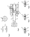
- Figure 2 is a longitudinal section of a flow control device and water recycling.
- Figure 3 is a partial section on a larger scale of the regulator debit.
- Figures 4, 5 and 6 illustrate on a larger scale three positions different from the flow regulator depending on the water temperature.
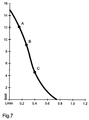
- Figure 7 illustrates the relationship between flow and water pressure as a function the position of the flow regulator and therefore the water temperature.
- Figure 8 illustrates two variants of a detail of the flow regulator.
- Figure 9 is a section on a larger scale of the recycling device.
- FIGS 10, 11 and 12 illustrate different positions of the water recycling according to the temperature of this water.
- Figure 13 is a diagram illustrating the stroke of the element thermostatic flow control and recycling device depending on the temperature of the water leaving the heater.
- the device for continuously heating a liquid at constant temperature comprises a room temperature water tank 1, a pump 2 sucking up water or liquid contained in the tank 1, a heating body 3 through which the water or the pumped liquid and comprising a use outlet fitted with a valve 4.
- the cold water pump 2 has characteristics adapted to the desired use, for example the preparation of coffee, in particular as regards concerns its "Pressure-Flow" characteristics.
- This pump can be by electromechanical example and have characteristics similar to those shown in Figure 7.
- the tank 1 is fitted with a non-return valve 5 preventing any return of water or liquid in the tank 1 through the pipe 6 connecting it to the pump 2.
- the heater 3 has a power adapted to the nominal flow liquid to be heated and can consist of a water or liquid tube connected thermally to an electrical resistance.
- the set is made in one piece or by assembling or connecting the two tubes, one serving as a conduit liquid and the other housing the electrical resistance and has a low capacity calorific.
- the length of the tubes and their diameter are mainly dependent liquid flow rate and desired power.
- Such heaters exist and are available on the market.
- the section of the water tube is adapted to the flow nominal of the continuous heating device and can be realized in various materials, especially stainless steel and possibly treated for limit its scaling.
- the illustrated continuous heating device also includes a device regulating the water flow and recycling the water or liquid when the latter has not reached its set temperature.
- This flow regulator-recycler assembly 7 comprises a cold part 7a containing the flow regulator and a hot part 7b containing a regulator thermostatic and water recycler.
- the hot part of this regulator assembly flow-recycler is preferably fixed or mounted on the heating body 3.
- This regulator-recycler 7 assembly is supplied with cold water by the pump 2 via the inlet 8 of its cold part to supply the flow regulator whose outlet 9 feeds the inlet 10 of the heating body 3.
- the outlet 11 of the body heater is connected to the input 12 of the hot part 7b of this set 7.
- This hot part 7b of the assembly 7 has two outlets, one for use 13 hot water and the other one for recycling water 14 which has not yet reached its conservation temperature.
- the use outlet 13 is connected by the valve 4 to a percolator 15 for preparing coffee for example or any other device for using the liquid heated.
- the flow regulator-recycler assembly 7 is illustrated more detailed in FIGS. 2 to 12 and comprises a body in two parts 7a, 7b cylindrical mounted end to end axially one on the other but isolated thermally relative to each other.
- the cold part 7a containing the flow regulator, has a bore central, axial, receiving an adjustment rod 16 sliding in this bore thanks to seals 17, 18, 19.
- This cold part 7a of the assembly 7 comprises a water inlet chamber 20, annular and located between the seals 18 and 19, in direct connection with the cold water inlet 8 supplied by the pump 2.
- This cold part 7a of the assembly 7 also includes an outlet chamber of water 21, annular and located between the seals 17 and 18, in connection direct with outlet 9 supplying the heating body with cold water.
- the flow regulator consists of a nozzle, the section of which water passage is variable depending on the axial position of the rod 16.
- This nozzle is formed by a radial slot 22 formed in the rod 16 and opening on its periphery allowing the entry chamber 20 to be connected to the outlet 21 of the cold part 7a of the assembly 7 according to the axial position of the rod 16 by a channel of minimum section up to a maximum section.
- the shape of this radial groove 22 may have a slope continuous or in steps. We can thus by choosing the shape of the section of the groove 22 define the function according to which the water flow varies according to the axial displacements of the rod 16 in the body 7a.
- the hot part 7b of the assembly 7 has a larger bore diameter than that of the cold part 7a in which the head 16a of the rod slides 16 using a seal 23.
- a thermostatic element 24 is fixed to using a ring 25 on the body 7b of the assembly 7.
- the movable piston 26 of this thermostatic element 24 bears against the bottom of the bore provided in the head 16a of the rod 16.
- This hot part 7b of the assembly 7 comprises a first chamber 27 supplied with hot water by the inlet 12 of the hot part supplied by the outlet 11 of the heating body 3.
- This first chamber 27 is directly connected at the outlet 13 of this hot part supplying the valve 4 and the percolator 15.
- the peripheral surface of the head 16a of the rod 16 has a countersink 28 radial over part of its length so that the first chamber 27 can be connected, depending on the position of the rod 16, with the recycling outlet 14 of the assembly 7.
- This recycling outlet 14 is connected to the conduit 6 connecting the tank 1 at pump 2.
- a spring 30 tends to hold the rod 16 in a rest position, moved towards the hot part 7a, position for which the water flow cold regulated by nozzle 22 is minimum and for which the recycling outlet of water 14 is connected to the first chamber 27 of the hot part 7b of the assembly 7.
- thermosensitive element 24 can be of the wax cartridge, liquid vaporization type, metal, shape memory and high expansion metals for example.
- the characteristic sought in this application is mainly its ability to produce a displacement under stress, for a temperature precise.
- the criteria of hysteresis, fidelity, speed and cost mean that the wax cartridge elements are particularly suitable for their use made in this flow regulation and water recycling device.
- the characteristic of such a thermostatic element with a wax cartridge is illustrated in as an example in Figure 13.
- the rod 16 In the stopped position, the rod 16 is in the rest position, moved towards the left under the action of spring 30 so that the cold water inlet chamber 20 is connected to the outlet chamber 21 of the flow regulator by a small section of the nozzle 22. The flow of cold water is therefore low. Still in this rest position, the first chamber 27 of the hot part 7b is connected by the milling 28 at the recycling outlet 14 of the hot part 7b.
- the heating element 3 When the user switches on the heating device, he energizes the heating element 3.
- the low thermal inertia of this heating element allows rapid rise in temperature.
- a thermostatic switch 29 fixed on the heating body switches on automatic or manual operation of the water pump 2.
- the pump thus supplies the heating body 3 with cold water, with a low flow rate, the flow regulator being in minimum flow position.
- the water leaving the body of heater is introduced into the first chamber 27 of the recycler and raises awareness the thermostatic element 24.
- the displacement of the rod 16 under the effect of the thermostatic element is insufficient to isolate the chamber 27 from the recycling outlet 14 and all the water pumped is recycled to the inlet of pump 2, mixed with cold water. In effect, as long as sufficient pressure does not build up in chamber 27, pressure greater than the holding force of valve 4, water cannot be dispensed in the percolator.
- rod 16 moves to the right, increasing the cross-section of the nozzle 22 and decreasing that of the nozzle 28.
- the regulator flow is in the position illustrated in Figure 4 and the recycler in the position illustrated in the Figure 10 and the operating point is that at A in Figures 7 and 13.
- the piston 26 of the thermosensitive element 24 moves the rod 16 increasing the water flow cold to its nominal value and reduces the cross-section of the recycling nozzle 28.
- nominal temperature for example 90 °
- the position of nozzles 22 and 28 are illustrated in Figures 5 and 11 and the operating point corresponds to the point B of Figures 7 and 13.
- the recycling nozzle 28 is closed, the pressure rises in chamber 27 and exceeds the holding force of valve 4 and the percolator is supplied.
- the rod 16 continues its stroke to the right and the nozzle 22 further increases its section and the flow becomes much higher than the nominal flow ( Figures 6, 12) and the operating point is located in C ( Figures 7 and 13) so that, automatically, the temperature of the water arriving in chamber 27 decreases, the heating body no longer being sufficient to heat to a desired temperature a water flow significantly greater than the nominal flow for which it is intended. Thus, the rod 16 moves to the left, again reducing the flow of cold water.
- the temperature leaving water is thus automatically regulated at its nominal value of desired use.
- one of the essential characteristics of the invention lies in the fact of having between the pump, the heating body and the percolator a device for regulating the flow of cold water and recycling heated water when it does not reach its nominal temperature, these two functions being controlled simultaneously by a single heat-sensitive element.
- this double regulation of the flow rate of the entry of cold water into the heating body and the distribution of water to the percolator or its recycling can be obtained, preferably mechanically, but using a device which would achieved differently from that described, but also by electromechanical regulation or electronic from a single water temperature sensor leaving the heating body.
- the present invention also relates to a method of heating in flow of a liquid, usually water, at a constant temperature depending on which is pumped from a cold water tank or at room temperature a quantity of water through a heating body having a low inertia thermal to deliver hot water at a determined temperature at a exit from use, for example a percolator.
- This process is distinguished by the fact that depending on the temperature of the water leaving the heating body we regulate on the one hand the flow of cold water delivered to the heating body and on the other hand the rate recycling hot water to the pump inlet. According to this process, the water is only delivered at the end of use when it reaches its temperature nominal and hot water reaches a determined pressure.
- a single sensor temperature controls the regulation of the cold water flow and simultaneously the hot water recycling rate.
- the hot water exceeds the set nominal temperature, the cold water flow delivered to the heater increases further, causing a drop in temperature of the water leaving the heating body.
- the heating method and device continuous of a liquid include:
- the flow regulation is carried out by a variable nozzle device 22 controlled by a thermosensitive element 24 placed in the outgoing hot water circuit a heater 3.
- the heating body 3 can be of constant power and adapted to the flow desired water, without the need for a large heat capacity or a large thermal inertia.
- the regulation of the cold water flow makes it possible to limit the phenomenon scaling, important and difficult to solve in temperature water circuits high.
- the flow regulation is carried out by variation of the passage section of water, or gradually depending on the displacement caused by the element thermostatic, either in stages.
- the water flow is much lower than that which can be brought to the desired temperature taking into account the heating power, as long as the set temperature is not reached.
- the flow is close to the flow nominal fixed by the heating power.
- the recycling device is controlled by the same heat-sensitive element, with a minimum cost objective.
- This construction allows a great compactness, a mass of parts minimum and a very low volume of water, which gives a very rapid preheating.
- the preheating of the hot part is controlled by an element thermostatic 29 mechanical or electronic.
- the thermostatic element 29 controls the starting of the pump automatically or informs the user that the preheating is finished.
- the device for regulating the water flow cold entering the heating body and the water recycling device leaving of the heating element as long as its temperature does not reach a set value are constructively grouped into a single set controlled by a single heat-sensitive element. This is advantageous from the constructive point of view, cost and size.
- these two flow control devices cold water and recycling water leaving the heating body to the tank, the inlet of the pump or in a tarpaulin could be separate.
- the command of these devices by the temperature of the water leaving the heating body is preferably carried out using a single heat-sensitive element but in variant each device could be controlled by a separate sensor.
Abstract
Description
La présente invention a pour objet un dispositif et un procédé de chauffage en continu d'un liquide à une température constante. Une application particulière de ce dispositif peut être le chauffage à une température constante et précise pour permettre par exemple la réalisation de préparations alimentaires.The subject of the present invention is a heating device and method continuously from a liquid at a constant temperature. A particular application of this device can be heating to a constant and precise temperature for allow for example the preparation of food preparations.
En particulier, ce dispositif et ce procédé peuvent être utilisés avantageusement pour le chauffage de l'eau sous pression destinée à la préparation de café.In particular, this device and this method can be used advantageously for heating pressurized water intended for coffee preparation.
Pour la préparation de café on connaít des dispositifs de chauffage d'eau discontinus dans lesquels une quantité d'eau déterminée est chauffée, puis utilisée à l'aide d'une pompe pour la préparation du café. Dans de tels dispositifs, le volume d'eau disponible est limité, le temps de préchauffage est important et une attente entre chaque préparation de café est inévitable. De plus, ces dispositifs sont encombrants et onéreux.For the preparation of coffee we know water heating devices discontinuous in which a given quantity of water is heated, then used with a pump to prepare coffee. In such devices, the volume of water available is limited, the preheating time is important and a wait between each coffee preparation is inevitable. In addition, these devices are bulky and expensive.
Il existe également des dispositifs de chauffage d'eau en continu, l'eau étant chauffée lors de son passage dans un canal ou une tubulure noyée dans un bloc à forte capacité thermique pour garantir une température constante. Le volume d'eau utilisable est limité par la capacité thermique du bloc, par ailleurs les dispositifs nécessaires pour réguler l'alimentation électrique et/ou la quantité d'eau délivrée ne permettent pas d'atteindre une précision de la température suffisante avec des moyens économiques. Ici également, le temps de préchauffe est long.There are also continuous water heaters, water being heated as it passes through a channel or tubing embedded in a block with high thermal capacity to guarantee a constant temperature. The usable water volume is limited by the thermal capacity of the block, moreover the devices necessary to regulate the power supply and / or the quantity of water not sufficient to achieve sufficient temperature accuracy with economic means. Here too, the preheating time is long.
De tels dispositifs de chauffage en continu d'eau pour la production de café
sont connus par exemple des documents suivants : EP 0 307 955, EP 0 676 163,
EP 0 771 542 ou FR 2 683 135.Such devices for continuously heating water for the production of coffee
The following documents are known, for example: EP 0 307 955, EP 0 676 163,
EP 0 771 542 or
Le but de la présente invention est de permettre la réalisation d'un dispositif de chauffage en continu d'un liquide à une température constante qui soit à la fois économique, précis en ce qui concerne la température de sortie du liquide, dont le corps de chauffe ne nécessite pas une grande inertie thermique et ne nécessitant donc pas un long temps de préchauffage.The object of the present invention is to allow the production of a device continuously heating a liquid to a constant temperature which is both economical, precise with regard to the liquid outlet temperature, the heating element does not require a large thermal inertia and does not require so not a long warm-up time.
La présente invention a pour objet un dispositif et un procédé de chauffage
d'un liquide en continu à une température constante obviant aux inconvénients
des dispositifs connus et permettant de réaliser les buts précités et pour ce faire le
dispositif selon l'invention comporte les caractéristiques énumérées à la
revendication 1 et le procédé celles énumérées à la revendication 15.The subject of the present invention is a heating device and method
of a liquid continuously at a constant temperature overcoming the drawbacks
known devices which make it possible to achieve the above-mentioned aims and to do this the
device according to the invention includes the characteristics listed in
Le dessin annexé illustre schématiquement et à titre d'exemple une forme d'exécution du dispositif de chauffage selon l'invention.The attached drawing illustrates schematically and by way of example a shape of execution of the heating device according to the invention.
La figure 1 est un schéma bloc du dispositif de chauffage en continu.Figure 1 is a block diagram of the continuous heating device.
La figure 2 est une coupe longitudinale d'un dispositif de régulation de débit et de recyclage d'eau.Figure 2 is a longitudinal section of a flow control device and water recycling.
La figure 3 est une coupe partielle à plus grande échelle du régulateur de débit.Figure 3 is a partial section on a larger scale of the regulator debit.
Les figures 4, 5 et 6 illustrent à plus grande échelle trois positions différentes du régulateur de débit en fonction de la température de l'eau.Figures 4, 5 and 6 illustrate on a larger scale three positions different from the flow regulator depending on the water temperature.
La figure 7 illustre la relation entre le débit et la pression d'eau en fonction de la position du régulateur de débit et donc de la température de l'eau.Figure 7 illustrates the relationship between flow and water pressure as a function the position of the flow regulator and therefore the water temperature.
La figure 8 illustre deux variantes d'un détail du régulateur de débit.Figure 8 illustrates two variants of a detail of the flow regulator.
La figure 9 est une coupe à plus grande échelle du dispositif de recyclage.Figure 9 is a section on a larger scale of the recycling device.
Les figures 10, 11 et 12 illustrent différentes positions du dispositif de recyclage d'eau en fonction de la température de cette eau.Figures 10, 11 and 12 illustrate different positions of the water recycling according to the temperature of this water.
La figure 13 est un diagramme illustrant la course de l'élément thermostatique du dispositif de régulation du débit et de recyclage en fonction de la température de l'eau sortant du corps de chauffe.Figure 13 is a diagram illustrating the stroke of the element thermostatic flow control and recycling device depending on the temperature of the water leaving the heater.
Le dispositif de chauffage en continu d'un liquide à température constante
selon le mode d'exécution illustré à titre d'exemple au dessin comporte un
réservoir d'eau à température ambiante 1, une pompe 2 aspirant de l'eau ou du
liquide contenu dans le réservoir 1, un corps de chauffe 3 traversé par l'eau ou le
liquide pompé et comportant une sortie d'utilisation munie d'une soupape 4.The device for continuously heating a liquid at constant temperature
according to the embodiment illustrated by way of example in the drawing comprises a
room
La pompe à eau froide 2 comporte des caractéristiques adaptées à
l'utilisation désirée, par exemple la préparation de café, notamment en ce qui
concerne ses caractéristiques "Pression-Débit". Cette pompe peut être par
exemple de type électromécanique et présenter des caractéristiques semblables à
celles représentées à la figure 7.The
Le réservoir 1 est équipé d'un clapet de non retour 5 évitant tout retour
d'eau ou de liquide dans le réservoir 1 par la canalisation 6 le reliant à la pompe 2.The
Le corps de chauffe 3 dispose d'une puissance adaptée au débit nominal
du liquide à chauffer et peut être constitué d'un tube d'eau ou de liquide relié
thermiquement à une résistance électrique. L'ensemble est réalisé d'une seule
pièce ou par assemblage ou liaison des deux tubes, l'un servant de conduit au
liquide et l'autre logeant la résistance électrique et présente une faible capacité
calorifique. La longueur des tubes et leur diamètre sont principalement dépendant
du débit de liquide et de la puissance désirée. De tels corps de chauffe existent et
sont disponibles sur le marché. La section du tube d'eau est adaptée au débit
nominal du dispositif de chauffage en continu et peut être réalisé en divers
matériaux, notamment en acier inoxydable et éventuellement être traité pour
limiter son entartrage.The
Le dispositif de chauffage en continu illustré comporte encore un dispositif de régulation du débit d'eau et de recyclage de l'eau ou du liquide lorsque celui-ci n'a pas atteint sa température de consigne.The illustrated continuous heating device also includes a device regulating the water flow and recycling the water or liquid when the latter has not reached its set temperature.
Cet ensemble régulateur de débit-recycleur 7 comporte une partie froide 7a
contenant le régulateur de débit et une partie chaude 7b contenant un régulateur
thermostatique et le recycleur d'eau. La partie chaude de cet ensemble régulateur
de débit-recycleur est de préférence fixée ou montée sur le corps de chauffe 3.
Cet ensemble régulateur de débit-recycleur 7 est alimenté en eau froide par la
pompe 2 par l'entrée 8 de sa partie froide pour alimenter le régulateur de débit
dont la sortie 9 alimente l'entrée 10 du corps de chauffe 3. La sortie 11 du corps
de chauffe est reliée à l'entrée 12 de la partie chaude 7b de cet ensemble 7. Cette
partie chaude 7b de l'ensemble 7 comporte deux sorties, l'une d'utilisation 13 de
l'eau chaude et l'autre de recyclage 14 de l'eau n'ayant pas encore atteint sa
température de consigne.This flow regulator-
La sortie d'utilisation 13 est reliée par la soupape 4 à un percolateur 15 pour
la préparation de café par exemple ou à tout autre appareil d'utilisation du liquide
chauffé.The
L'ensemble régulateur de débit-recycleur 7 est illustré de façon plus
détaillée aux figures 2 à 12 et comporte un corps en deux parties 7a, 7b
cylindriques montées bout à bout axialement l'une sur l'autre mais isolées
thermiquement l'une par rapport à l'autre.The flow regulator-
La partie froide 7a, contenant le régulateur de débit, comporte un alésage
central, axial, recevant une tige de réglage 16 coulissant dans cet alésage grâce à
des joints d'étanchéité 17, 18, 19. Cette partie froide 7a de l'ensemble 7 comporte
une chambre d'entrée d'eau 20, annulaire et située entre les joints d'étanchéité 18
et 19, en liaison directe avec l'entrée d'eau froide 8 alimentée par la pompe 2.
Cette partie froide 7a de l'ensemble 7 comporte encore une chambre de sortie
d'eau 21, annulaire et située entre les joints d'étanchéité 17 et 18, en liaison
directe avec la sortie 9 alimentant le corps de chauffe en eau froide.The
Le régulateur de débit est constitué par un ajutage dont la section de
passage de l'eau est variable en fonction de la position axiale de la tige 16. Cet
ajutage est formé par une fente radiale 22 pratiquée dans la tige 16 et débouchant
sur sa périphérie permettant de relier la chambre d'entrée 20 à la chambre de
sortie 21 de la partie froide 7a de l'ensemble 7 suivant la position axiale de la tige
16 par un canal de section minimale jusqu'à une section maximale. Comme on le
voit à la figure 8, la forme de cette rainure radiale 22 peut présenter une pente
continue ou en escalier. On peut ainsi en choisissant la forme de la section de la
rainure 22 définir la fonction selon laquelle le débit d'eau varie en fonction des
déplacements axiaux de la tige 16 dans le corps 7a.The flow regulator consists of a nozzle, the section of which
water passage is variable depending on the axial position of the
La partie chaude 7b de l'ensemble 7 comporte un alésage de plus grand
diamètre que celui de la partie froide 7a dans lequel coulisse la tête 16a de la tige
16 à l'aide d'un joint d'étanchéité 23. Un élément thermostatique 24 est fixé à
l'aide d'une bague 25 sur le corps 7b de l'ensemble 7. Le piston mobile 26 de cet
élément thermostatique 24 prend appui au fond de l'alésage prévu dans la tête
16a de la tige 16.The
Cette partie chaude 7b de l'ensemble 7 comporte une première chambre 27
alimentée en eau chaude par l'entrée 12 de la partie chaude alimentée par la
sortie 11 du corps de chauffe 3. Cette première chambre 27 est reliée directement
à la sortie 13 de cette partie chaude alimentant la soupape 4 et le percolateur 15.This
La surface périphérique de la tête 16a de la tige 16 présente une fraisure
28 radiale sur une partie de sa longueur de telle sorte que la première chambre 27
puisse être reliée, suivant la position de la tige 16, avec la sortie de recyclage 14
de l'ensemble 7. Cette sortie de recyclage 14 est reliée au conduit 6 reliant le
réservoir 1 à la pompe 2.The peripheral surface of the
Un ressort 30 tend à maintenir la tige 16 dans une position de repos,
déplacée en direction de la partie chaude 7a, position pour laquelle le débit d'eau
froide régulé par l'ajutage 22 est minimum et pour laquelle la sortie de recyclage
d'eau 14 est reliée à la première chambre 27 de la partie chaude 7b de l'ensemble
7.A
Le régulateur de débit et le recycleur sont actionnés par la tige 16, elle-même
soumise à l'action de l'élément thermosensible 24. Cet élément
thermosensible 24 peut être du type à cartouche à cire, à vaporisation de liquide,
à métal, à mémoire de forme et à métaux à forte dilatation par exemple.The flow regulator and the recycler are actuated by the
La caractéristique recherchée dans cette application est principalement sa capacité à produire un déplacement sous contrainte, pour une température précise. Les critères d'hystérésis, de fidélité, de rapidité et de coût font que les éléments à cartouche à cire conviennent particulièrement à l'utilisation qui en est faite dans ce dispositif de régulation de débit et de recyclage d'eau. La caractéristique d'un tel élément thermostatique à cartouche de cire est illustrée à titre d'exemple à la figure 13.The characteristic sought in this application is mainly its ability to produce a displacement under stress, for a temperature precise. The criteria of hysteresis, fidelity, speed and cost mean that the wax cartridge elements are particularly suitable for their use made in this flow regulation and water recycling device. The characteristic of such a thermostatic element with a wax cartridge is illustrated in as an example in Figure 13.
Le fonctionnement du dispositif de chauffage en continu décrit est le suivant:The operation of the continuous heating device described is the next:
En position d'arrêt, la tige 16 est en position de repos, déplacée vers la
gauche sous l'action du ressort 30 de sorte que la chambre d'entrée d'eau froide
20 est reliée à la chambre de sortie 21 du régulateur de débit par une faible
section de l'ajutage 22. Le débit d'eau froide est donc faible. Toujours dans cette
position de repos, la première chambre 27 de la partie chaude 7b est reliée par la
fraisure 28 à la sortie de recyclage 14 de la partie chaude 7b.In the stopped position, the
Lorsque l'usager enclenche le dispositif de chauffage, il met sous tension le
corps de chauffe 3. La faible inertie thermique de ce corps de chauffe permet une
montée en température rapide. Lorsque la température de préchauffage est
atteinte, un contacteur thermostatique 29 fixé sur le corps de chauffe met en
marche, automatiquement ou manuellement, la pompe à eau 2. La pompe
alimente ainsi le corps de chauffe 3 en eau froide, avec un faible débit, le
régulateur de débit étant en position de débit minimum. L'eau sortant du corps de
chauffe est introduite dans la première chambre 27 du recycleur et sensibilise
l'élément thermostatique 24. Tant que la température de fonctionnement n'est pas
atteinte, le déplacement de la tige 16 sous l'effet de l'élément thermostatique est
insuffisant pour isoler la chambre 27 de la sortie de recyclage 14 et toute l'eau
pompée est recyclée à l'entrée de la pompe 2, mélangée à de l'eau froide. En
effet, tant qu'une pression suffisante ne s'établit pas dans la chambre 27, pression
supérieure à la force de retenue de la soupape 4, l'eau ne peut pas être distribuée
au percolateur. When the user switches on the heating device, he energizes the
Au fur et à mesure que la température de l'eau arrivant dans la chambre 27
augmente, la tige 16 se déplace vers la droite, augmentant la section de passage
de l'ajutage 22 et diminuant celle de l'ajutage 28.As the temperature of the
Ainsi, à titre d'exemple, pour une température de l'eau dans la première
chambre 27 de la partie chaude 7b inférieure ou égale à 86°C, le régulateur de
débit est en position illustrée à la figure 4 et le recycleur en position illustrée à la
figure 10 et le point de fonctionnement est celui en A des figures 7 et 13.So, for example, for a water temperature in the
Au-delà de la température minimale désirée pour l'eau d'utilisation, le piston
26 de l'élément thermosensible 24 déplace la tige 16 augmentant le débit d'eau
froide jusqu'à sa valeur nominale et diminue la section de l'ajutage de recyclage
28. A la température nominale, par exemple 90°, la position des ajutages 22 et 28
sont illustrés aux figures 5 et 11 et le point de fonctionnement correspond au point
B des figures 7 et 13. L'ajutage de recyclage 28 est obturé, la pression monte
dans la chambre 27 et dépasse la force de retenue de la soupape 4 et le
percolateur est alimenté.Beyond the minimum temperature desired for the water used, the
Si la température dépasse cette valeur nominale, la tige 16 poursuit sa
course vers la droite et l'ajutage 22 augmente encore sa section et le débit devient
très supérieur au débit nominal (figures 6, 12) et le point de fonctionnement se
situe en C (figures 7 et 13) de sorte que, automatiquement, la température de
l'eau arrivant dans la chambre 27 diminue, le corps de chauffe ne suffisant plus à
chauffer à la température voulue un débit d'eau sensiblement plus grand que le
débit nominal pour lequel il est prévu. Ainsi, la tige 16 se déplace vers la gauche,
réduisant à nouveau le débit d'eau froide.If the temperature exceeds this nominal value, the
Tant que le dispositif de chauffage débite de l'eau chaude, la température de l'eau de sortie est ainsi automatiquement régulée à sa valeur nominale d'utilisation désirée.As long as the heater delivers hot water, the temperature leaving water is thus automatically regulated at its nominal value of desired use.
Lorsque l'utilisateur déclenche le dispositif de chauffage, la pompe 2 et le corps de chauffe sont déclenchés. When the user turns on the heater, pump 2 and the heaters are triggered.
Le dispositif de chauffage décrit est intéressant et avantageux à plusieurs titres :
- il permet d'éviter la distribution d'eau tant que celle-ci n'a pas atteint la température désirée.
- il diminue le temps d'attente avant de pouvoir utiliser de l'eau chaude car il réduit le débit d'eau à chauffer tant que la température nominale n'est pas atteinte.
- l'eau d'une température inférieure à celle d'utilisation désirée est recyclée à l'entrée de la pompe en mélange avec de l'eau froide, ce qui réduit l'entartrage.
- le dispositif de régulation du débit et de recyclage est entièrement mécanique, facile à réaliser et n'utilise qu'un seul élément thermostatique pour le réglage du débit d'eau froide et pour le recyclage de l'eau insuffisamment chaude pour l'utilisation. Il est simple à réaliser, à utiliser et peu coûteux et sa précision de fonctionnement est grande.
- it avoids the distribution of water until it has reached the desired temperature.
- it reduces the waiting time before being able to use hot water because it reduces the flow of water to be heated until the nominal temperature is reached.
- the water of a temperature lower than that of desired use is recycled at the entry of the pump in mixture with cold water, which reduces the scaling.
- the flow control and recycling device is entirely mechanical, easy to make and uses only one thermostatic element for adjusting the flow of cold water and for recycling insufficiently hot water for use. It is simple to make, to use and inexpensive and its operating precision is high.
Comme on l'a vu précédemment, une des caractéristiques essentielles de l'invention réside dans le fait de disposer entre la pompe, le corps de chauffe et le percolateur un dispositif de régulation du débit d'eau froide et de recyclage de l'eau chauffée lorsqu'elle n'atteint pas sa température nominale, ces deux fonctions étant commandées simultanément par un seul élément thermosensible.As we saw earlier, one of the essential characteristics of the invention lies in the fact of having between the pump, the heating body and the percolator a device for regulating the flow of cold water and recycling heated water when it does not reach its nominal temperature, these two functions being controlled simultaneously by a single heat-sensitive element.
Bien entendu, cette double régulation du débit de l'entrée d'eau froide dans le corps de chauffe et de la distribution d'eau au percolateur ou son recyclage peut être obtenue, de préférence mécaniquement, mais à l'aide d'un dispositif qui serait réalisé différemment de celui décrit, mais également par une régulation électromécanique ou électronique à partir d'un seul capteur de température de l'eau sortant du corps de chauffe.Of course, this double regulation of the flow rate of the entry of cold water into the heating body and the distribution of water to the percolator or its recycling can be obtained, preferably mechanically, but using a device which would achieved differently from that described, but also by electromechanical regulation or electronic from a single water temperature sensor leaving the heating body.
La présente invention a également pour objet un procédé de chauffage en continu d'un liquide, généralement de l'eau, à une température constante selon lequel on pompe à partir d'un réservoir d'eau froide ou à température ambiante une quantité d'eau à travers un corps de chauffe présentant une faible inertie thermique pour délivrer de l'eau chaude à une température déterminée à une sortie d'utilisation, par exemple un percolateur. Ce procédé se distingue par le fait qu'en fonction de la température de l'eau sortant du corps de chauffe on régule d'une part le débit d'eau froide délivré au corps de chauffe et d'autre part le taux de recyclage d'eau chaude vers l'admission de la pompe. Selon ce procédé, l'eau n'est délivrée à la sortie d'utilisation que lorsqu'elle atteint sa température nominale et que l'eau chaude atteint une pression déterminée. Un seul capteur de température commande la régulation du débit d'eau froide et simultanément le taux de recyclage de l'eau chaude.The present invention also relates to a method of heating in flow of a liquid, usually water, at a constant temperature depending on which is pumped from a cold water tank or at room temperature a quantity of water through a heating body having a low inertia thermal to deliver hot water at a determined temperature at a exit from use, for example a percolator. This process is distinguished by the fact that depending on the temperature of the water leaving the heating body we regulate on the one hand the flow of cold water delivered to the heating body and on the other hand the rate recycling hot water to the pump inlet. According to this process, the water is only delivered at the end of use when it reaches its temperature nominal and hot water reaches a determined pressure. A single sensor temperature controls the regulation of the cold water flow and simultaneously the hot water recycling rate.
Par ce procédé, au début du chauffage de l'eau, on ne délivre qu'un faible débit d'eau au corps de chauffe, ce qui permet un chauffage rapide de l'eau et tant que l'eau n'a pas atteint une température d'utilisation minimum, cette eau est recyclée vers l'entrée de la pompe. Ce n'est que lorsque la température de l'eau sortant du corps de chauffe atteint sa valeur nominale que l'eau n'est plus recyclée, provoquant sa montée en pression et sa distribution à la sortie d'utilisation d'eau chaude. Simultanément, le débit d'eau froide délivré au corps de chauffe augmente.By this process, at the start of water heating, only a small amount is delivered. water flow to the heater, which allows rapid heating of the water and that the water has not reached a minimum operating temperature, this water is recycled to the pump inlet. Only when the water temperature leaving the heater reaches its nominal value that the water is no longer recycled, causing its pressure build-up and its distribution at the outlet use of hot water. Simultaneously, the flow of cold water delivered to the body of heat increases.
Si l'eau chaude dépasse la température nominale fixée, le débit d'eau froide délivré au corps de chauffe augmente encore, provoquant ainsi une chute de température de l'eau sortant du corps de chauffe.If the hot water exceeds the set nominal temperature, the cold water flow delivered to the heater increases further, causing a drop in temperature of the water leaving the heating body.
Par ce procédé, on obtient une réduction du temps de chauffage nécessaire à porter la température de l'eau sortant du corps de chauffe à sa valeur nominale, on évite de délivrer de l'eau à la sortie d'utilisation tant que celle-ci n'a pas atteint sa valeur nominale et on régule ensuite la valeur de la température de l'eau distribuée par la régulation du débit de l'eau froide entrant dans le corps de chauffe. By this process, a reduction in the heating time required is obtained to bring the temperature of the water leaving the heating body to its nominal value, we avoid delivering water at the outlet of use until it has reached its nominal value and then regulate the value of the water temperature distributed by regulating the flow of cold water entering the body of heated.
En résumé, on peut retenir que le procédé et le dispositif de chauffage en continu d'un liquide comportent :In summary, it can be remembered that the heating method and device continuous of a liquid include:
A/ La régulation de la température de l'eau en sortie par une régulation du
débit de l'eau à la température ambiante contenue dans un réservoir 1 et délivrée
par une pompe 2.A / The regulation of the temperature of the water leaving by a regulation of the
water flow at room temperature contained in a
La régulation de débit est réalisée par un dispositif d'ajutage variable 22
piloté par un élément thermosensible 24 placé dans le circuit d'eau chaude sortant
d'un corps de chauffe 3.The flow regulation is carried out by a
Le corps de chauffe 3 peut être de puissance constante et adaptée au débit
d'eau souhaité, sans besoin d'une grande capacité calorifique ni d'une grande
inertie thermique.The
Son temps de préchauffe sera donc minimum et le coût de ces corps de chauffe produits en très grandes séries est faible.Its preheating time will therefore be minimum and the cost of these bodies heater produced in very large series is low.
La régulation du débit d'eau froide permet de limiter le phénomène d'entartrage, important et délicat à résoudre dans les circuits d'eau à température élevée.The regulation of the cold water flow makes it possible to limit the phenomenon scaling, important and difficult to solve in temperature water circuits high.
La régulation de débit est réalisée par variation de la section de passage de l'eau, soit progressivement en fonction du déplacement provoqué par l'élément thermostatique, soit par étapes.The flow regulation is carried out by variation of the passage section of water, or gradually depending on the displacement caused by the element thermostatic, either in stages.
Le débit de l'eau est très inférieur à celui pouvant être porté à la température désirée compte tenu de la puissance de chauffe, tant que la température de consigne n'est pas atteinte.The water flow is much lower than that which can be brought to the desired temperature taking into account the heating power, as long as the set temperature is not reached.
Aux environs de la température de consigne, le débit est proche du débit nominal fixé par la puissance de chauffe.Around the set temperature, the flow is close to the flow nominal fixed by the heating power.
Lorsque la température dépasse la température de consigne, le débit devient très supérieur au débit nominal.When the temperature exceeds the set temperature, the flow becomes much higher than the nominal flow.
B/ Le recyclage de l'eau chaude vers une bâche, ou dans le réservoir, ou vers l'aspiration de la pompe et ce, tant que la température de consigne n'est pas atteinte. B / The recycling of hot water to a tarpaulin, or in the tank, or towards the pump suction, as long as the set temperature is not reached.
Le dispositif de recyclage est piloté par le même élément thermosensible, dans un objectif de coût minimal.The recycling device is controlled by the same heat-sensitive element, with a minimum cost objective.
Dans le cas de recyclage à l'aspiration de la pompe, un mélange eau chaude - eau froide permet de limiter les risques d'entartrage de la pompe.In the case of recycling at the pump suction, a water mixture hot - cold water reduces the risk of scaling of the pump.
De plus, le dispositif de régulation de débit et de recyclage est réalisé de
préférence en deux parties :
Cette construction permet une grande compacité, une masse des pièces minimum et un volume d'eau très faible, ce qui donne une préchauffe très rapide.This construction allows a great compactness, a mass of parts minimum and a very low volume of water, which gives a very rapid preheating.
La préchauffe de la partie chaude est contrôlée par un élément thermostatique 29 mécanique ou électronique.The preheating of the hot part is controlled by an element thermostatic 29 mechanical or electronic.
Lorsque la température de préchauffe est atteinte, l'élément thermostatique
29 commande la mise en marche de la pompe de manière automatique ou
informe l'utilisateur que la préchauffe est terminée.When the preheating temperature is reached, the
On obtient ainsi le fonctionnement suivant :
Dans la forme d'exécution illustrée, le dispositif de régulation du débit d'eau froide entrant dans le corps de chauffe et le dispositif de recyclage de l'eau sortant du corps de chauffe tant que sa température n'atteint pas une valeur de consigne minimale sont regroupés constructivement en un seul ensemble commandé par un seul élément thermosensible. Ceci est avantageux du point de vue constructif, coût et encombrement.In the illustrated embodiment, the device for regulating the water flow cold entering the heating body and the water recycling device leaving of the heating element as long as its temperature does not reach a set value are constructively grouped into a single set controlled by a single heat-sensitive element. This is advantageous from the constructive point of view, cost and size.
Dans une variante toutefois, ces deux dispositifs de régulation du débit d'eau froide et de recyclage de l'eau sortant du corps de chauffe vers le réservoir, l'entrée de la pompe ou dans une bâche pourraient être distincts. La commande de ces dispositifs par la température de l'eau sortant du corps de chauffe s'effectue de préférence à l'aide d'un seul élément thermosensible mais en variante chaque dispositif pourrait être commandé par un capteur séparé.In a variant, however, these two flow control devices cold water and recycling water leaving the heating body to the tank, the inlet of the pump or in a tarpaulin could be separate. The command of these devices by the temperature of the water leaving the heating body is preferably carried out using a single heat-sensitive element but in variant each device could be controlled by a separate sensor.
Claims (20)
Priority Applications (19)
| Application Number | Priority Date | Filing Date | Title |
|---|---|---|---|
| AT99121661T ATE299350T1 (en) | 1999-11-02 | 1999-11-02 | DEVICE AND METHOD FOR CONTINUOUS HEATING OF A CONSTANT TEMPERATURE BEVERAGE |
| SI9930801T SI1097663T1 (en) | 1999-11-02 | 1999-11-02 | Device and method for continuous heating of liquids at a constant temperature |
| PT99121661T PT1097663E (en) | 1999-11-02 | 1999-11-02 | SLIDE AND CONTINUOUS HEATING PROCESS OF A LIQUID AT A CONSTANT TEMPERATURE |
| DK99121661T DK1097663T3 (en) | 1999-11-02 | 1999-11-02 | Apparatus and method for continuously heating a liquid at a constant temperature |
| ES99121661T ES2244138T3 (en) | 1999-11-02 | 1999-11-02 | DEVICE AND HEATING PROCEDURE CONTINUED FROM A LIQUID TO A CONSTANT TEMPERATURE. |
| EP99121661A EP1097663B1 (en) | 1999-11-02 | 1999-11-02 | Device and method for continuous heating of liquids at a constant temperature |
| DE69926130T DE69926130T2 (en) | 1999-11-02 | 1999-11-02 | Apparatus and method for continuous heating of a constant temperature beverage |
| CNB008181012A CN100438810C (en) | 1999-11-02 | 2000-09-28 | Device and method for continuous heating of liquid to constant temp. |
| IL14928400A IL149284A (en) | 1999-11-02 | 2000-09-28 | Device and method for the continuous heating of a liquid to a constant temperature |
| BR0015262-5A BR0015262A (en) | 1999-11-02 | 2000-09-28 | Device and method for the continuous heating of a liquid to a constant temperature |
| JP2001534276A JP2003512878A (en) | 1999-11-02 | 2000-09-28 | Apparatus and method for continuously heating a liquid to a constant temperature |
| AU79091/00A AU780841B2 (en) | 1999-11-02 | 2000-09-28 | Device and method for the continuous heating of a liquid to a constant temperature |
| MXPA02004374A MXPA02004374A (en) | 1999-11-02 | 2000-09-28 | Device and method for the continuous heating of a liquid to a constant temperature. |
| PCT/EP2000/009510 WO2001032064A1 (en) | 1999-11-02 | 2000-09-28 | Device and method for the continuous heating of a liquid to a constant temperature |
| CA002390225A CA2390225A1 (en) | 1999-11-02 | 2000-09-28 | Device and method for the continuous heating of a liquid to a constant temperature |
| TW089120769A TWI231752B (en) | 1999-11-02 | 2000-10-05 | Device and method for the continuous heating of a liquid to a constant temperature |
| ARP000105768A AR026328A1 (en) | 1999-11-02 | 2000-11-01 | DEVICE AND PROCEDURE FOR CONTINUOUS WARMING OF A CONSTANT TEMPERATURE LIQUID |
| US10/125,621 US6661968B2 (en) | 1999-11-02 | 2002-04-17 | Continuous heating of liquid to constant temperature |
| NO20022023A NO320824B1 (en) | 1999-11-02 | 2002-04-29 | Apparatus and method for continuously heating a liquid to constant temperature |
Applications Claiming Priority (1)
| Application Number | Priority Date | Filing Date | Title |
|---|---|---|---|
| EP99121661A EP1097663B1 (en) | 1999-11-02 | 1999-11-02 | Device and method for continuous heating of liquids at a constant temperature |
Publications (2)
| Publication Number | Publication Date |
|---|---|
| EP1097663A1 true EP1097663A1 (en) | 2001-05-09 |
| EP1097663B1 EP1097663B1 (en) | 2005-07-13 |
Family
ID=8239310
Family Applications (1)
| Application Number | Title | Priority Date | Filing Date |
|---|---|---|---|
| EP99121661A Expired - Lifetime EP1097663B1 (en) | 1999-11-02 | 1999-11-02 | Device and method for continuous heating of liquids at a constant temperature |
Country Status (19)
| Country | Link |
|---|---|
| US (1) | US6661968B2 (en) |
| EP (1) | EP1097663B1 (en) |
| JP (1) | JP2003512878A (en) |
| CN (1) | CN100438810C (en) |
| AR (1) | AR026328A1 (en) |
| AT (1) | ATE299350T1 (en) |
| AU (1) | AU780841B2 (en) |
| BR (1) | BR0015262A (en) |
| CA (1) | CA2390225A1 (en) |
| DE (1) | DE69926130T2 (en) |
| DK (1) | DK1097663T3 (en) |
| ES (1) | ES2244138T3 (en) |
| IL (1) | IL149284A (en) |
| MX (1) | MXPA02004374A (en) |
| NO (1) | NO320824B1 (en) |
| PT (1) | PT1097663E (en) |
| SI (1) | SI1097663T1 (en) |
| TW (1) | TWI231752B (en) |
| WO (1) | WO2001032064A1 (en) |
Cited By (10)
| Publication number | Priority date | Publication date | Assignee | Title |
|---|---|---|---|---|
| CN100454201C (en) * | 2007-07-18 | 2009-01-21 | 邬志坚 | Heating control system for drinking machine with electrothermal film heater |
| WO2009084060A1 (en) * | 2008-01-03 | 2009-07-09 | Essence-Sbt Sa | Delivering system for infusion-type beverages |
| WO2009087203A1 (en) | 2008-01-09 | 2009-07-16 | Gotec Sa | Heating positive-displacement pump for liquids |
| WO2010079115A2 (en) | 2009-01-08 | 2010-07-15 | Gotec Sa | Heating positive-displacement pump for liquids |
| WO2010079116A1 (en) | 2009-01-08 | 2010-07-15 | Gotec Sa | Method for supplying a volume of a hot beverage |
| WO2012069594A1 (en) | 2010-11-26 | 2012-05-31 | Gotec Sa | Positive-displacement liquid pump comprising a heating cartridge |
| WO2014053582A1 (en) | 2012-10-05 | 2014-04-10 | Gotec Sa | Pump using a heating volumetric liquid |
| CN105658125A (en) * | 2013-11-01 | 2016-06-08 | 皇家飞利浦有限公司 | Liquid heating device |
| EP2787868B1 (en) | 2011-12-07 | 2017-02-15 | Seb S.A. | Heating device for bringing liquid to the boil and beverage preparation apparatus comprising such a device |
| WO2017068537A1 (en) | 2015-10-23 | 2017-04-27 | Gotec Sa | Heating module for liquid pump |
Families Citing this family (21)
| Publication number | Priority date | Publication date | Assignee | Title |
|---|---|---|---|---|
| US6253663B1 (en) * | 2000-03-28 | 2001-07-03 | William L. Spencer | In-wall coffee maker |
| FR2855359B1 (en) * | 2003-05-19 | 2005-07-01 | Seb Sa | DEVICE FOR HEATING A LIQUID FOR AN ELECTRICAL APPLIANCE, AN ELECTRICAL APPLIANCE EQUIPPED WITH SUCH A DEVICE. |
| ES2247926B1 (en) * | 2004-05-20 | 2006-11-01 | Quality Espresso, Sa | DEVICE FOR TEMPERATURE CONTROL OF A DISPENSING GROUP IN A COFFEE PREPARATION MACHINE. |
| US20080295698A1 (en) * | 2004-06-10 | 2008-12-04 | The Technology Partnership Plc | Drink Machine |
| US20060011069A1 (en) * | 2004-07-19 | 2006-01-19 | Spencer William L | Coffee maker and method of use |
| FR2878023B1 (en) | 2004-11-15 | 2007-04-13 | Seb Sa | METHOD AND DEVICE FOR PROVIDING HOT WATER |
| WO2008083941A1 (en) † | 2007-01-09 | 2008-07-17 | Steiner Weggis Ag | Method and apparatus for the production of milk foam or milk-based drinks |
| US8180204B2 (en) * | 2007-07-02 | 2012-05-15 | Brewl Technologies, Inc. | Hot beverage brewing apparatus |
| CA2640783A1 (en) * | 2007-10-08 | 2009-04-08 | William L. Spencer | Coffee maker brewbasket with carafe locking mechanism |
| DK2252182T3 (en) * | 2008-01-24 | 2012-07-23 | Nestec Sa | ENERGY SAVING CONTROL FOR BEVERAGE COOKING DEVICES |
| EP2082669A2 (en) * | 2008-01-25 | 2009-07-29 | Nestec S.A. | Hybrid apparatus for preparing beverages |
| WO2012069958A1 (en) * | 2010-11-26 | 2012-05-31 | Koninklijke Philips Electronics N.V. | Device for making a beverage, adapted to accurately setting a dispense temperature of the beverage |
| US20130247777A1 (en) * | 2010-12-02 | 2013-09-26 | Nestec S.A. | Low-inertia thermal sensor in a beverage machine |
| USD677510S1 (en) | 2011-06-16 | 2013-03-12 | Calphalon Corporation | Coffee maker |
| ES2405295B1 (en) * | 2011-11-22 | 2014-08-05 | Jofemar, S.A. | WATER DISTRIBUTOR FOR INSTANT DRINK MACHINES AND INSTANT DRINK MACHINE THAT INCLUDES SUCH DISTRIBUTOR |
| ITRE20110109A1 (en) * | 2011-12-07 | 2013-06-08 | Redox S R L | ENERGY SAVING COFFEE MACHINE |
| JP2014061086A (en) * | 2012-09-20 | 2014-04-10 | Zojirushi Corp | Beverage extractor and operation method of beverage extractor |
| KR20150056781A (en) | 2012-09-21 | 2015-05-27 | 액세스 비지니스 그룹 인터내셔날 엘엘씨 | Selective water temperature component for use with water treatment systems |
| CN110402093A (en) | 2017-02-15 | 2019-11-01 | 2266170安大略省公司 | Beverage preparation and injected system |
| IT201900011745A1 (en) * | 2019-07-15 | 2021-01-15 | Irca Spa | ELECTRIC HEATER, IN PARTICULAR FOR A HOUSEHOLD APPLIANCE FOR THE PREPARATION OF HOT DRINKS |
| EP3808232A1 (en) * | 2019-10-14 | 2021-04-21 | Koninklijke Philips N.V. | An apparatus for preparing a hot liquid drink |
Citations (9)
| Publication number | Priority date | Publication date | Assignee | Title |
|---|---|---|---|---|
| DE2635046B1 (en) * | 1976-08-04 | 1977-07-21 | Bentz & Sohn Melitta | Coffee or tea machine with riser pipe and? a bimetal switch? Instantaneous water heater |
| GB2113813A (en) * | 1982-01-26 | 1983-08-10 | Scovill Inc | Electric coffee maker |
| EP0307955A1 (en) | 1987-09-21 | 1989-03-22 | Alberto Rolla | Coffee-making machine with a water heater device |
| EP0540440A1 (en) * | 1991-10-30 | 1993-05-05 | Reneka Industries | Improved injector device for a coffee machine, comprising a temperature regulating unit for the hot water, located close to the injection point |
| FR2683135A1 (en) | 1991-10-30 | 1993-05-07 | Reneka Ind Sa | Circuit for optimising and maintaining the temperature of water in a coffee-making machine |
| EP0676163A1 (en) | 1994-04-08 | 1995-10-11 | Sintra Holding Ag | Coffee brewer, esp. for domestic use |
| EP0771542A1 (en) | 1995-10-31 | 1997-05-07 | ILLYCAFFE' S.p.A. | Improvements to a coffee machine |
| EP0862883A1 (en) * | 1997-03-07 | 1998-09-09 | Wmf Württembergische Metallwarenfabrik Ag | Coffee preparing apparatus |
| FR2774882A1 (en) * | 1998-02-13 | 1999-08-20 | Seb Sa | ELECTRIC COFFEE MAKER OF THE EXPRESSO TYPE WITH THERMAL REGULATION |
Family Cites Families (2)
| Publication number | Priority date | Publication date | Assignee | Title |
|---|---|---|---|---|
| ATE243458T1 (en) * | 1996-12-23 | 2003-07-15 | Koninkl Philips Electronics Nv | COFFEE MACHINE |
| FR2767665B1 (en) * | 1997-09-02 | 1999-11-12 | Seb Sa | INFUSING APPARATUS |
-
1999
- 1999-11-02 EP EP99121661A patent/EP1097663B1/en not_active Expired - Lifetime
- 1999-11-02 PT PT99121661T patent/PT1097663E/en unknown
- 1999-11-02 AT AT99121661T patent/ATE299350T1/en not_active IP Right Cessation
- 1999-11-02 DK DK99121661T patent/DK1097663T3/en active
- 1999-11-02 ES ES99121661T patent/ES2244138T3/en not_active Expired - Lifetime
- 1999-11-02 SI SI9930801T patent/SI1097663T1/en unknown
- 1999-11-02 DE DE69926130T patent/DE69926130T2/en not_active Expired - Lifetime
-
2000
- 2000-09-28 IL IL14928400A patent/IL149284A/en not_active IP Right Cessation
- 2000-09-28 AU AU79091/00A patent/AU780841B2/en not_active Ceased
- 2000-09-28 CA CA002390225A patent/CA2390225A1/en not_active Abandoned
- 2000-09-28 MX MXPA02004374A patent/MXPA02004374A/en unknown
- 2000-09-28 JP JP2001534276A patent/JP2003512878A/en not_active Withdrawn
- 2000-09-28 WO PCT/EP2000/009510 patent/WO2001032064A1/en active IP Right Grant
- 2000-09-28 BR BR0015262-5A patent/BR0015262A/en not_active IP Right Cessation
- 2000-09-28 CN CNB008181012A patent/CN100438810C/en not_active Expired - Fee Related
- 2000-10-05 TW TW089120769A patent/TWI231752B/en not_active IP Right Cessation
- 2000-11-01 AR ARP000105768A patent/AR026328A1/en not_active Application Discontinuation
-
2002
- 2002-04-17 US US10/125,621 patent/US6661968B2/en not_active Expired - Lifetime
- 2002-04-29 NO NO20022023A patent/NO320824B1/en unknown
Patent Citations (9)
| Publication number | Priority date | Publication date | Assignee | Title |
|---|---|---|---|---|
| DE2635046B1 (en) * | 1976-08-04 | 1977-07-21 | Bentz & Sohn Melitta | Coffee or tea machine with riser pipe and? a bimetal switch? Instantaneous water heater |
| GB2113813A (en) * | 1982-01-26 | 1983-08-10 | Scovill Inc | Electric coffee maker |
| EP0307955A1 (en) | 1987-09-21 | 1989-03-22 | Alberto Rolla | Coffee-making machine with a water heater device |
| EP0540440A1 (en) * | 1991-10-30 | 1993-05-05 | Reneka Industries | Improved injector device for a coffee machine, comprising a temperature regulating unit for the hot water, located close to the injection point |
| FR2683135A1 (en) | 1991-10-30 | 1993-05-07 | Reneka Ind Sa | Circuit for optimising and maintaining the temperature of water in a coffee-making machine |
| EP0676163A1 (en) | 1994-04-08 | 1995-10-11 | Sintra Holding Ag | Coffee brewer, esp. for domestic use |
| EP0771542A1 (en) | 1995-10-31 | 1997-05-07 | ILLYCAFFE' S.p.A. | Improvements to a coffee machine |
| EP0862883A1 (en) * | 1997-03-07 | 1998-09-09 | Wmf Württembergische Metallwarenfabrik Ag | Coffee preparing apparatus |
| FR2774882A1 (en) * | 1998-02-13 | 1999-08-20 | Seb Sa | ELECTRIC COFFEE MAKER OF THE EXPRESSO TYPE WITH THERMAL REGULATION |
Cited By (14)
| Publication number | Priority date | Publication date | Assignee | Title |
|---|---|---|---|---|
| CN100454201C (en) * | 2007-07-18 | 2009-01-21 | 邬志坚 | Heating control system for drinking machine with electrothermal film heater |
| WO2009084060A1 (en) * | 2008-01-03 | 2009-07-09 | Essence-Sbt Sa | Delivering system for infusion-type beverages |
| US8727739B2 (en) | 2008-01-09 | 2014-05-20 | Gotec Sa | Heating pump for liquids |
| WO2009087203A1 (en) | 2008-01-09 | 2009-07-16 | Gotec Sa | Heating positive-displacement pump for liquids |
| WO2010079115A2 (en) | 2009-01-08 | 2010-07-15 | Gotec Sa | Heating positive-displacement pump for liquids |
| WO2010079116A1 (en) | 2009-01-08 | 2010-07-15 | Gotec Sa | Method for supplying a volume of a hot beverage |
| WO2012069594A1 (en) | 2010-11-26 | 2012-05-31 | Gotec Sa | Positive-displacement liquid pump comprising a heating cartridge |
| EP2787868B1 (en) | 2011-12-07 | 2017-02-15 | Seb S.A. | Heating device for bringing liquid to the boil and beverage preparation apparatus comprising such a device |
| WO2014053582A1 (en) | 2012-10-05 | 2014-04-10 | Gotec Sa | Pump using a heating volumetric liquid |
| US9897081B2 (en) | 2012-10-05 | 2018-02-20 | Gotec Sa | Heating positive-displacement liquid pump |
| CN105658125A (en) * | 2013-11-01 | 2016-06-08 | 皇家飞利浦有限公司 | Liquid heating device |
| CN105658125B (en) * | 2013-11-01 | 2019-05-03 | 皇家飞利浦有限公司 | Liquid heating apparatus |
| US10602876B2 (en) | 2013-11-01 | 2020-03-31 | Koninklijke Philips N.V. | Liquid heating device |
| WO2017068537A1 (en) | 2015-10-23 | 2017-04-27 | Gotec Sa | Heating module for liquid pump |
Also Published As
| Publication number | Publication date |
|---|---|
| ATE299350T1 (en) | 2005-07-15 |
| TWI231752B (en) | 2005-05-01 |
| EP1097663B1 (en) | 2005-07-13 |
| NO20022023D0 (en) | 2002-04-29 |
| AU780841B2 (en) | 2005-04-21 |
| BR0015262A (en) | 2002-06-25 |
| ES2244138T3 (en) | 2005-12-01 |
| CN1414837A (en) | 2003-04-30 |
| IL149284A (en) | 2005-09-25 |
| CA2390225A1 (en) | 2001-05-10 |
| WO2001032064A1 (en) | 2001-05-10 |
| DK1097663T3 (en) | 2005-11-14 |
| US20020141742A1 (en) | 2002-10-03 |
| DE69926130D1 (en) | 2005-08-18 |
| DE69926130T2 (en) | 2006-06-01 |
| IL149284A0 (en) | 2002-11-10 |
| JP2003512878A (en) | 2003-04-08 |
| PT1097663E (en) | 2005-09-30 |
| NO20022023L (en) | 2002-04-29 |
| MXPA02004374A (en) | 2002-08-20 |
| SI1097663T1 (en) | 2005-10-31 |
| US6661968B2 (en) | 2003-12-09 |
| CN100438810C (en) | 2008-12-03 |
| AR026328A1 (en) | 2003-02-05 |
| NO320824B1 (en) | 2006-01-30 |
| AU7909100A (en) | 2001-05-14 |
Similar Documents
| Publication | Publication Date | Title |
|---|---|---|
| EP1097663B1 (en) | Device and method for continuous heating of liquids at a constant temperature | |
| EP1812758B1 (en) | Method and device for supplying hot water | |
| EP1009270B1 (en) | Brewing unit for automatic beverage dispensers comprising in particular a boiler | |
| WO2003006857A1 (en) | Control valve for cooling circuit | |
| WO2006056705A1 (en) | Brewing beverage dispenser comprising an improved boiler and a method for the production thereof | |
| CH688631A5 (en) | thermostatically controlled valve with pressure equalization and volume control. | |
| WO2006070116A2 (en) | Piston gas regulator proof against upstream pressure variations | |
| EP1947385B1 (en) | Fuel injection device in a turbomachine | |
| FR2848895A1 (en) | Embedding tool for inserting fastener e.g. bolt, in surface, has metering unit with repression body laid out in chamber for pushing fuel, where repression body displaces volume of fuel and makes repression volume adjustable | |
| FR2693133A1 (en) | Spray apparatus, device for regulating the pressure of a liquid in a feed pipe of a spray gun and a device for controlling a spray apparatus. | |
| EP1376292A1 (en) | Single-lever thermostatic cartridge with ceramic discs | |
| WO2008078044A2 (en) | Glue dispensing device, gluing method, insulation glazing and spacer thereof provided with glue | |
| FR3044782A1 (en) | THERMOSTATIC MONOCOMMANDE CARTRIDGE AND MIXER FAUCET WITH SUCH A CARTRIDGE | |
| FR2767932A1 (en) | Fuel injection regulator for internal combustion engine | |
| EP0540440A1 (en) | Improved injector device for a coffee machine, comprising a temperature regulating unit for the hot water, located close to the injection point | |
| FR2541434A1 (en) | INSTANTANEOUS GAS WATER HEATER | |
| FR3065655A1 (en) | HEATER SPRAY GUN | |
| FR2637520A1 (en) | Integral soldering iron with automatic and simultaneous flow of the solder and of its flux | |
| FR2716955A1 (en) | Low-pressure gas burner carburation regulator | |
| FR2626501A1 (en) | Method of supplying extrusion or pulverisation means with a pasty substance, supply device and installation comprising the device | |
| FR2463447A1 (en) | VALVE FOR MAINTAINING THE OIL OF A HYDRAULIC SYSTEM WITH CONSTANT VISCOSITY BY A REGULATION USING A PRESSURE DROP | |
| EP3983193B1 (en) | Machine for injecting thermoplastic material | |
| FR2552846A1 (en) | HIGH TEMPERATURE LOW PRESSURE SAFETY VALVE | |
| EP1631445B1 (en) | Valve and supplying device for filling a moulding cavity with a polymerisable material | |
| EP0417005B1 (en) | System for injection moulding molten material into a receiving device such as a mould |
Legal Events
| Date | Code | Title | Description |
|---|---|---|---|
| PUAI | Public reference made under article 153(3) epc to a published international application that has entered the european phase |
Free format text: ORIGINAL CODE: 0009012 |
|
| AK | Designated contracting states |
Kind code of ref document: A1 Designated state(s): AT BE CH CY DE DK ES FI FR GB GR IE IT LI LU MC NL PT SE |
|
| AX | Request for extension of the european patent |
Free format text: AL;LT;LV;MK;RO;SI |
|
| 17P | Request for examination filed |
Effective date: 20010926 |
|
| AKX | Designation fees paid |
Free format text: AT BE CH CY DE DK ES FI FR GB GR IE IT LI LU MC NL PT SE |
|
| AXX | Extension fees paid |
Free format text: SI PAYMENT 20010926 |
|
| GRAP | Despatch of communication of intention to grant a patent |
Free format text: ORIGINAL CODE: EPIDOSNIGR1 |
|
| GRAS | Grant fee paid |
Free format text: ORIGINAL CODE: EPIDOSNIGR3 |
|
| GRAA | (expected) grant |
Free format text: ORIGINAL CODE: 0009210 |
|
| AK | Designated contracting states |
Kind code of ref document: B1 Designated state(s): AT BE CH CY DE DK ES FI FR GB GR IE IT LI LU MC NL PT SE |
|
| AX | Request for extension of the european patent |
Extension state: SI |
|
| REG | Reference to a national code |
Ref country code: GB Ref legal event code: FG4D Free format text: NOT ENGLISH |
|
| REG | Reference to a national code |
Ref country code: CH Ref legal event code: EP |
|
| REG | Reference to a national code |
Ref country code: IE Ref legal event code: FG4D Free format text: LANGUAGE OF EP DOCUMENT: FRENCH |
|
| REF | Corresponds to: |
Ref document number: 69926130 Country of ref document: DE Date of ref document: 20050818 Kind code of ref document: P |
|
| REG | Reference to a national code |
Ref country code: GR Ref legal event code: EP Ref document number: 20050402648 Country of ref document: GR |
|
| REG | Reference to a national code |
Ref country code: PT Ref legal event code: SC4A Effective date: 20050719 |
|
| GBT | Gb: translation of ep patent filed (gb section 77(6)(a)/1977) |
Effective date: 20050919 |
|
| PGFP | Annual fee paid to national office [announced via postgrant information from national office to epo] |
Ref country code: GR Payment date: 20051012 Year of fee payment: 7 |
|
| PGFP | Annual fee paid to national office [announced via postgrant information from national office to epo] |
Ref country code: CY Payment date: 20051013 Year of fee payment: 7 |
|
| PGFP | Annual fee paid to national office [announced via postgrant information from national office to epo] |
Ref country code: MC Payment date: 20051026 Year of fee payment: 7 |
|
| REG | Reference to a national code |
Ref country code: SE Ref legal event code: TRGR |
|
| PGFP | Annual fee paid to national office [announced via postgrant information from national office to epo] |
Ref country code: SE Payment date: 20051107 Year of fee payment: 7 |
|
| PGFP | Annual fee paid to national office [announced via postgrant information from national office to epo] |
Ref country code: FI Payment date: 20051114 Year of fee payment: 7 |
|
| REG | Reference to a national code |
Ref country code: DK Ref legal event code: T3 |
|
| REG | Reference to a national code |
Ref country code: ES Ref legal event code: FG2A Ref document number: 2244138 Country of ref document: ES Kind code of ref document: T3 |
|
| PLBE | No opposition filed within time limit |
Free format text: ORIGINAL CODE: 0009261 |
|
| STAA | Information on the status of an ep patent application or granted ep patent |
Free format text: STATUS: NO OPPOSITION FILED WITHIN TIME LIMIT |
|
| 26N | No opposition filed |
Effective date: 20060418 |
|
| PG25 | Lapsed in a contracting state [announced via postgrant information from national office to epo] |
Ref country code: FI Free format text: LAPSE BECAUSE OF NON-PAYMENT OF DUE FEES Effective date: 20061102 |
|
| PG25 | Lapsed in a contracting state [announced via postgrant information from national office to epo] |
Ref country code: SE Free format text: LAPSE BECAUSE OF NON-PAYMENT OF DUE FEES Effective date: 20061103 |
|
| PG25 | Lapsed in a contracting state [announced via postgrant information from national office to epo] |
Ref country code: MC Free format text: LAPSE BECAUSE OF NON-PAYMENT OF DUE FEES Effective date: 20061130 |
|
| EUG | Se: european patent has lapsed | ||
| PG25 | Lapsed in a contracting state [announced via postgrant information from national office to epo] |
Ref country code: CY Free format text: LAPSE BECAUSE OF NON-PAYMENT OF DUE FEES Effective date: 20061102 |
|
| PG25 | Lapsed in a contracting state [announced via postgrant information from national office to epo] |
Ref country code: GR Free format text: LAPSE BECAUSE OF NON-PAYMENT OF DUE FEES Effective date: 20070604 |
|
| PGFP | Annual fee paid to national office [announced via postgrant information from national office to epo] |
Ref country code: NL Payment date: 20081103 Year of fee payment: 10 Ref country code: LU Payment date: 20081031 Year of fee payment: 10 Ref country code: IE Payment date: 20081114 Year of fee payment: 10 Ref country code: DK Payment date: 20081114 Year of fee payment: 10 |
|
| PGFP | Annual fee paid to national office [announced via postgrant information from national office to epo] |
Ref country code: PT Payment date: 20081013 Year of fee payment: 10 Ref country code: AT Payment date: 20081112 Year of fee payment: 10 |
|
| PGFP | Annual fee paid to national office [announced via postgrant information from national office to epo] |
Ref country code: BE Payment date: 20081110 Year of fee payment: 10 |
|
| PGFP | Annual fee paid to national office [announced via postgrant information from national office to epo] |
Ref country code: GB Payment date: 20081029 Year of fee payment: 10 |
|
| REG | Reference to a national code |
Ref country code: PT Ref legal event code: MM4A Free format text: LAPSE DUE TO NON-PAYMENT OF FEES Effective date: 20100503 |
|
| BERE | Be: lapsed |
Owner name: SOC. DES PRODUITS *NESTLE S.A. Effective date: 20091130 |
|
| REG | Reference to a national code |
Ref country code: NL Ref legal event code: V1 Effective date: 20100601 |
|
| REG | Reference to a national code |
Ref country code: DK Ref legal event code: EBP |
|
| GBPC | Gb: european patent ceased through non-payment of renewal fee |
Effective date: 20091102 |
|
| PG25 | Lapsed in a contracting state [announced via postgrant information from national office to epo] |
Ref country code: PT Free format text: LAPSE BECAUSE OF NON-PAYMENT OF DUE FEES Effective date: 20100503 |
|
| REG | Reference to a national code |
Ref country code: IE Ref legal event code: MM4A |
|
| PG25 | Lapsed in a contracting state [announced via postgrant information from national office to epo] |
Ref country code: AT Free format text: LAPSE BECAUSE OF NON-PAYMENT OF DUE FEES Effective date: 20091102 |
|
| PG25 | Lapsed in a contracting state [announced via postgrant information from national office to epo] |
Ref country code: NL Free format text: LAPSE BECAUSE OF NON-PAYMENT OF DUE FEES Effective date: 20100601 Ref country code: IE Free format text: LAPSE BECAUSE OF NON-PAYMENT OF DUE FEES Effective date: 20091102 Ref country code: BE Free format text: LAPSE BECAUSE OF NON-PAYMENT OF DUE FEES Effective date: 20091130 |
|
| PG25 | Lapsed in a contracting state [announced via postgrant information from national office to epo] |
Ref country code: GB Free format text: LAPSE BECAUSE OF NON-PAYMENT OF DUE FEES Effective date: 20091102 |
|
| PG25 | Lapsed in a contracting state [announced via postgrant information from national office to epo] |
Ref country code: DK Free format text: LAPSE BECAUSE OF NON-PAYMENT OF DUE FEES Effective date: 20091130 |
|
| PGFP | Annual fee paid to national office [announced via postgrant information from national office to epo] |
Ref country code: IT Payment date: 20101112 Year of fee payment: 12 |
|
| PG25 | Lapsed in a contracting state [announced via postgrant information from national office to epo] |
Ref country code: LU Free format text: LAPSE BECAUSE OF NON-PAYMENT OF DUE FEES Effective date: 20091102 |
|
| PGFP | Annual fee paid to national office [announced via postgrant information from national office to epo] |
Ref country code: ES Payment date: 20101217 Year of fee payment: 12 |
|
| PG25 | Lapsed in a contracting state [announced via postgrant information from national office to epo] |
Ref country code: IT Free format text: LAPSE BECAUSE OF NON-PAYMENT OF DUE FEES Effective date: 20111102 |
|
| REG | Reference to a national code |
Ref country code: ES Ref legal event code: FD2A Effective date: 20131029 |
|
| PG25 | Lapsed in a contracting state [announced via postgrant information from national office to epo] |
Ref country code: ES Free format text: LAPSE BECAUSE OF NON-PAYMENT OF DUE FEES Effective date: 20111103 |
|
| REG | Reference to a national code |
Ref country code: DE Ref legal event code: R082 Ref document number: 69926130 Country of ref document: DE Representative=s name: ANDRAE WESTENDORP PATENTANWAELTE PARTNERSCHAFT, DE |
|
| PGFP | Annual fee paid to national office [announced via postgrant information from national office to epo] |
Ref country code: CH Payment date: 20141112 Year of fee payment: 16 Ref country code: FR Payment date: 20141110 Year of fee payment: 16 |
|
| PGFP | Annual fee paid to national office [announced via postgrant information from national office to epo] |
Ref country code: DE Payment date: 20151028 Year of fee payment: 17 |
|
| REG | Reference to a national code |
Ref country code: CH Ref legal event code: PL |
|
| PG25 | Lapsed in a contracting state [announced via postgrant information from national office to epo] |
Ref country code: CH Free format text: LAPSE BECAUSE OF NON-PAYMENT OF DUE FEES Effective date: 20151130 Ref country code: LI Free format text: LAPSE BECAUSE OF NON-PAYMENT OF DUE FEES Effective date: 20151130 |
|
| REG | Reference to a national code |
Ref country code: FR Ref legal event code: ST Effective date: 20160729 |
|
| PG25 | Lapsed in a contracting state [announced via postgrant information from national office to epo] |
Ref country code: FR Free format text: LAPSE BECAUSE OF NON-PAYMENT OF DUE FEES Effective date: 20151130 |
|
| REG | Reference to a national code |
Ref country code: DE Ref legal event code: R119 Ref document number: 69926130 Country of ref document: DE |
|
| PG25 | Lapsed in a contracting state [announced via postgrant information from national office to epo] |
Ref country code: DE Free format text: LAPSE BECAUSE OF NON-PAYMENT OF DUE FEES Effective date: 20170601 |