EP1097654A2 - Expandable luggage - Google Patents
Expandable luggage Download PDFInfo
- Publication number
- EP1097654A2 EP1097654A2 EP00106808A EP00106808A EP1097654A2 EP 1097654 A2 EP1097654 A2 EP 1097654A2 EP 00106808 A EP00106808 A EP 00106808A EP 00106808 A EP00106808 A EP 00106808A EP 1097654 A2 EP1097654 A2 EP 1097654A2
- Authority
- EP
- European Patent Office
- Prior art keywords
- component
- wall panel
- luggage
- item
- bridge plate
- Prior art date
- Legal status (The legal status is an assumption and is not a legal conclusion. Google has not performed a legal analysis and makes no representation as to the accuracy of the status listed.)
- Withdrawn
Links
- 230000002093 peripheral effect Effects 0.000 claims abstract description 18
- 239000000463 material Substances 0.000 claims abstract description 17
- 238000006073 displacement reaction Methods 0.000 claims description 4
- 230000000712 assembly Effects 0.000 abstract description 3
- 238000000429 assembly Methods 0.000 abstract description 3
- 239000004744 fabric Substances 0.000 description 5
- 239000011324 bead Substances 0.000 description 2
- 238000002347 injection Methods 0.000 description 2
- 239000007924 injection Substances 0.000 description 2
- IJJWOSAXNHWBPR-HUBLWGQQSA-N 5-[(3as,4s,6ar)-2-oxo-1,3,3a,4,6,6a-hexahydrothieno[3,4-d]imidazol-4-yl]-n-(6-hydrazinyl-6-oxohexyl)pentanamide Chemical compound N1C(=O)N[C@@H]2[C@H](CCCCC(=O)NCCCCCC(=O)NN)SC[C@@H]21 IJJWOSAXNHWBPR-HUBLWGQQSA-N 0.000 description 1
- 238000005452 bending Methods 0.000 description 1
- 238000010276 construction Methods 0.000 description 1
- 230000008878 coupling Effects 0.000 description 1
- 238000010168 coupling process Methods 0.000 description 1
- 238000005859 coupling reaction Methods 0.000 description 1
- 230000002708 enhancing effect Effects 0.000 description 1
- 238000012856 packing Methods 0.000 description 1
Images




Classifications
-
- A—HUMAN NECESSITIES
- A45—HAND OR TRAVELLING ARTICLES
- A45C—PURSES; LUGGAGE; HAND CARRIED BAGS
- A45C7/00—Collapsible or extensible purses, luggage, bags or the like
- A45C7/0018—Rigid or semi-rigid luggage
- A45C7/0022—Rigid or semi-rigid luggage comprising an integrated expansion device
- A45C7/0031—Rigid or semi-rigid luggage comprising an integrated expansion device telescopic
Definitions
- the present invention relates to luggage, especially travel luggage, and in particular to luggage that can be expanded when desired.
- a traveler does not need as much luggage space for a trip of short duration as for a long one.
- a business traveler does not need as much luggage space as a recreational traveler, especially one who needs both casual and dress clothes. In most cases, men need less luggage space than women.
- One way for travelers to provide for both smaller and larger luggage space requirements is to have a moderately sized suitcase for some trips and a large one for other trips. Another way is to have two moderate sized suitcases and use only one when possible and use both when a larger capacity is needed.
- An expandable item of luggage offers the traveler a possible savings in cost as compared to the costs of purchasing more than one piece of luggage.
- the capability of expanding a piece of luggage permits a traveler to change the carrying capacity in the course of a trip. Not infrequently, a traveler will make purchases on a trip and will need more room for the return trip than for travel to a destination.
- An object of the present invention is to provide an item of expandable luggage of the "hard” type that has a high degree of geometric stability when expanded. It is, in particular, an objective of the invention to provide a highly effective coupling between two frame components that move apart when the luggage item is expanded so that relative movements of the two frame components are minimized. A further object is to provide a hard expandable luggage item that is easily changed between a smaller volume and a larger volume.
- an item of expandable luggage that includes a frame having a first substantially rigid component and a second substantially rigid component, each of which includes a pair of opposite rectangular planar wall panels and which together with a pair of wall members form the peripheral boundary of a variable volume receptacle and a rectangular area.
- a peripherally continuous gusset of flexible material is connected between the wall panels and wall members of the two frame components and provides, when the luggage item is expanded, a portion of the peripheral wall of the receptacle.
- a bridge assembly joins each wall panel of the first component to a corresponding wall panel of the second component in coplanar relation and for linear displacement of the two components toward and away from each other.
- Each bridge assembly includes a pair of parallel spaced-apart slide rails affixed to the wall panel of the first component, a substantially rigid bridge plate affixed to the wall panel of the second component and slidably received by the slide rails, and a releasable latch that couples the bridge plate to the wall panel of the first component in at least one position in which the second component is held securely in a position spaced apart from the first component.
- the bridge plate/slide rail arrangement provides high rigidity to the luggage item in the expanded state. Forces tending to displace the frame components in the planes of each of the bridge plates and the wall panels with which the bridge plates are associated are transmitted from the second frame component to the bridge plate and from the bridge plate through the slides to the first component.
- the spacing of the slide rails and the corresponding length of the bridge plate between the slide rails provide considerable strength and stiffness that resists relative displacements of the components and maintains both the coplanar relationships of all of the peripheral wall panels and a parallel relationship between the two frame components.
- the bridge plate/slide rail arrangement maintains stability of the frame system in both the collapsed and expanded states against displacement in mutually perpendicular directions in a plane perpendicular to the planes of the peripheral walls of the frame components, against skewing of one component relative to the other about any axis perpendicular to that plane, and tilting of one component relative to the other about any line in that plane.
- the latch holds the two frame components rigidly at the predetermined spacing in the expanded state so that the luggage item cannot collapse under loads imposed on it.
- the latch may permit the bridge plate to be latched to the wall panel of the first component in a plurality of positions, and even in an infinite number of positions. Infinite latch positions are provided in a simple and effective way by a panel of loop material affixed to the bridge panel, a flexible band attached to the wall panel of the first component, and a strip of hook material affixed to the flexible band and releasably engageable with the loop material on the bridge plate.
- latches may include one based on a cam cutout in the bridge plate and a cam disc carried for rotation by the wall panel of the first component and one composed of a resiliently biased catch button carried by the wall panel of the first component and an abutment edge on the bridge plate engageable by the catch button.
- each slide rail includes a body portion engaging the wall panel of the first component and a projecting flange portion defining with the wall panel of the first component a guide groove.
- the bridge panel in that configuration resides in engagement with the wall panel with which it is associated and gains stiffness from such engagement - the co-engaging portions of the bridge plate and the wall panel are linked along the slide rails and provide a stiff "unit" that resists bending perpendicular to the plane of the wall panel.
- the bridge plate is fastened to the wall panel of the second frame component and gains support and stiffness from such attachment, again enhancing the rigidity of the bridge assembly.
- each slide rail it is desirable for the flange portion of each slide rail to have a guide rib projecting toward the wall panel of the first component.
- the bridge plate has along opposite edges a guide groove receiving the guide rib on the flange portion of the slide rail. The rib and groove guiding relationship stiffens both the slide rail and the edges of the bridge plate.
- a main frame component 10 has a pair of rectangular planar side wall panels 12 and 14, a bottom wall member 16 and a top wall member 18, which are substantially rigid and rigidly connected at the corners.
- a main frame component 10 may also have a partial or complete rigid back wall panel.
- a secondary frame component 20 is formed of opposite rectangular planar panels 22 and 24 and top and bottom members 26 and 28, which as a practical matter will usually also be rectangular planar panels of sheet material.
- the main frame component 10 receives a cover 30 of a durable fabric.
- the sides, top and bottom of the secondary frame receive a fabric cover 32.
- Access to the interior of the luggage item is through a front opening that is closed by a panel 34, is joined to the cover 32 along one edge and can be opened and closed by undoing and doing up a zipper 36 that extends along three edges.
- the main part (main frame 10 and its cover 30) of the luggage item is joined to the secondary part (secondary frame 20 and its cover 32, 34) by a gusset 36 of a durable, flexible material that extends along the entire perimeter of the luggage item (along the top, bottom and both side walls).
- the gusset 36 peripherally bounds that part of the entire volume of the main compartment by which the volume of the item is increased upon movement of the secondary unit away from the main unit.
- a zipper 40 that extends about the entire perimeter of the item is done up.
- the gusset 36 folds into the interior of the item.
- the main frame component 10 is joined to the secondary frame component 20 by two identical bridge assemblies 50, one of which is associated with the side panels 12 and 22 and the other with the side panels 14 and 24.
- Bach assembly consists of a pair of parallel spaced-apart slide rails 52 that are affixed to the wall panel 12, 14 of the main frame component 10, a substantially rigid bridge plate 54 that is affixed to the wall panel 22, 24 of the secondary frame component 20 and is slidably received by the slide rails 52, and a latch 56 (shown schematically as an arrow in Fig. 1) that releasably connects the bridge plate 54 to the wall panel 12, 14 of the main frame component 10 in at least one position in which the secondary frame component 20 is held spaced apart from the main frame component 10, thereby to retain the luggage item in the expanded state.
- a suitable slide rail 52 is injection molded from a durable polymeric material and has a body portion 52a with countersunk holes 52b for screws or rivets by which it is fastened to the wall panel 12, 14 and a flange portion 52c with a rib 52d.
- the underside of the body portion 52a bears against the surface of the panel 12, 14 (or a fabric liner within the luggage item).
- the flange portion 52c forms with the wall panel 12, 14 a guide groove that accepts the edge of the panel in sliding/guiding relation.
- a suitable bridge panel 54 is injection molded from a durable polymeric material and has a recess 54a on the side facing into the interior of the luggage item, a slot 54b adjacent one edge, holes 54c for screws or rivets by which it is fastened to the wall panels 22, 24 of the secondary frame component 20, and edge flanges 54d with ribs 54e along each side edge.
- the bottom edge 54f is smoothly rounded. Rows of tiny fabric anchor pins 54g protrude from the back surface near the upper edge.
- the guiding/sliding relationship between the slide rails 52 and bridge plate is shown in Figs. 12 and 13.
- latch can be used to releasably connect the bridge plate to the main frame wall panels 12, 14 in the expanded state of the luggage item.
- the bridge plate 54 of Figs. 7 to 11 is designed for the latch 56 shown in Figs. 14 and 15, the showing being schematic for greater clarity.
- a piece 56a of a loop material, such as "VELMAT,” is hemmed along one end to form a bead 45b, inserted through the slot 54b in the bridge panel 54, trained along the front of the bridge panel and folded over the top of the bridge panel.
- the loop piece 54a is clamped in place; the hem/bead holds the lower edge, and the clamping, along with the tiny pins 54g, holds the upper edge.
- Other ways of fastening the loop piece 56a to the bridge plate 54 are, of course, possible.
- the loop piece 56a is received in the recess 54a of the bridge panel 54.
- a piece 56c of smooth strong flexible material is suitably fastened to the main wall panel 12, 14 near the edge closer to the secondary wall panel 22, 24, turned around the rounded bottom edge 54f of the bridge panel and guided freely along the front face of the bridge panel.
- a strip 56d of hook cloth stitched to the free end of the piece 56c is releasably anchored to the loop piece 56a at any desired location by the mutual tenacity of the loop and hook materials. The user may easily and quickly adjust the luggage item to any of an infinite number of volumes within the range of the smallest volume with the zipper 40 done up to the largest with the zipper 40 undone and the gusset 36 fully extended by grasping the ends of the pieces 56c of both bridge assemblies 50 and pulling them toward the open front of the item.
- Pulling on the pieces 56c draws the pieces 56c around the lower edge 54f of the bride panel 54 and moves the secondary frame 20 away from the main frame. At any desired point of movement, the user may anchor the hook strips 56d to the loop piece 56a, thereby setting the volume of the luggage item to the directed size.
- the bridge assembly stabilizes the shape of the luggage item by preventing up and down movements, side to side movements, rotational skewing movements, and side to side and front to back cocking movements of the secondary unit relative to the main unit. More simply put, the sliding support of the bridge plate 54 by the slide rails 52 holds the secondary unit stationary laterally, longitudinally and rotationally relative to the main unit in the plane of the rear edge of the secondary frame and maintains the plane of the rear edge of the secondary unit parallel to the plane of the front edge of the main unit.
- the latch 56 keeps the luggage item from collapsing. If the luggage item is adjusted to less than the maximum volume, the latch does not preclude movement of the secondary unit to the maximum volume position. Such movement is not of concern.
- the purpose of the latch is to maintain a desired minimum volume in an expanded state for the convenience of the user when he or she is packing the luggage and to avoid crushing the contents when the luggage is handled or stowed for transport.
- FIG. 16 Another bridge assembly 150, as shown in Figs. 16 to 18, has a slightly modified bridge plate 154 and a push-button catch unit 156.
- the bridge plate 154 has a recess (not shown per se but apparent from the front as a protuberance 154a) in the rear surface that accepts the catch unit 156 in the retracted state (Fig. 16).
- a push button 156a of the catch unit is resiliently biased relative to the casing 156b of the catch unit such that in the expanded state of the luggage item it engages a rounded edge 154b of the bridge panel at the lower edge of the recess/protuberance 156a, thus latching the luggage item in the expanded state (Fig. 18).
- the front face of the push button is tapered so that when the user pulls the secondary unit away from the main unit from the retracted position, the lower edge of a hole 154c in the recess/protuberance 154a cams the push button against its resiliency, so the user does not have to push the push buttons to expand the luggage item.
- Pushing in on the release button 156a disengages the button from the shoulder 154b, allowing the luggage item to be restored from the expanded state (Fig. 18) to the retracted state (Fig. 16).
- a bridge assembly 250 that is based on a cam latch, as shown in Figs. 19 and 20, includes a modified bridge plate 254, which has a cam hole 254a, and a cam disc 256, which is pivotally attached by a screw 256a (or rivet) to the main frame wall panel 12, 14 and overlies the bridge plate 254.
- An arcuate cam follower rib 256b that protrudes from the back face of the cam disc 256 pushes the bridge plate 254 from the retracted state (Fig. 19) to the expanded state (Fig. 20) when a user manually rotates the cam disc 256 clockwise about the pivot screw 256a.
- a rib 256c on the front face of the cam disc 256 can be engaged by the user's fingers to facilitate rotating the cam disc.
- a ridge 254b in the cam hole 254a captures the cam follower rib 256b when the luggage item is in the expanded state. Attaining the expanded state requires a slight movement of the secondary unit to a position farther away from the main unit than the final expanded position.
Landscapes
- Purses, Travelling Bags, Baskets, Or Suitcases (AREA)
- Vehicle Step Arrangements And Article Storage (AREA)
Abstract
Description
- The present invention relates to luggage, especially travel luggage, and in particular to luggage that can be expanded when desired.
- The needs of travelers for luggage space can vary considerably, depending on the duration of a trip, the nature of the trip in terms of the types of clothing and other gear required, and the climate of the destination. For example, regardless of the purpose and the climate, a traveler does not need as much luggage space for a trip of short duration as for a long one. Generally, a business traveler does not need as much luggage space as a recreational traveler, especially one who needs both casual and dress clothes. In most cases, men need less luggage space than women.
- One way for travelers to provide for both smaller and larger luggage space requirements is to have a moderately sized suitcase for some trips and a large one for other trips. Another way is to have two moderate sized suitcases and use only one when possible and use both when a larger capacity is needed. There have also been various proposals for expandable luggage. An expandable item of luggage offers the traveler a possible savings in cost as compared to the costs of purchasing more than one piece of luggage. Moreover, the capability of expanding a piece of luggage permits a traveler to change the carrying capacity in the course of a trip. Not infrequently, a traveler will make purchases on a trip and will need more room for the return trip than for travel to a destination.
- Most previously known luggage having a variable volume is of the "soft" type, such as a duffle bag with expandable sections that can be collapsed and secured to a main section. The expandable "hard" luggage that is currently available lacks rigidity when expanded due to inadequate linking of separate rigid frame components that move away from each other when the luggage is expanded. US PS 5 671 831 describes and shows an item of hard luggage in which only the bottom panels of a main frame and a secondary frame are coupled pay slide rails or plates, thus leaving the upper parts of the frames without any linkages and making the item subject to deformation.
- An object of the present invention is to provide an item of expandable luggage of the "hard" type that has a high degree of geometric stability when expanded. It is, in particular, an objective of the invention to provide a highly effective coupling between two frame components that move apart when the luggage item is expanded so that relative movements of the two frame components are minimized. A further object is to provide a hard expandable luggage item that is easily changed between a smaller volume and a larger volume.
- The foregoing objects are attained, in accordance with the present invention, by an item of expandable luggage that includes a frame having a first substantially rigid component and a second substantially rigid component, each of which includes a pair of opposite rectangular planar wall panels and which together with a pair of wall members form the peripheral boundary of a variable volume receptacle and a rectangular area. A peripherally continuous gusset of flexible material is connected between the wall panels and wall members of the two frame components and provides, when the luggage item is expanded, a portion of the peripheral wall of the receptacle. A bridge assembly joins each wall panel of the first component to a corresponding wall panel of the second component in coplanar relation and for linear displacement of the two components toward and away from each other. Each bridge assembly includes a pair of parallel spaced-apart slide rails affixed to the wall panel of the first component, a substantially rigid bridge plate affixed to the wall panel of the second component and slidably received by the slide rails, and a releasable latch that couples the bridge plate to the wall panel of the first component in at least one position in which the second component is held securely in a position spaced apart from the first component.
- The bridge plate/slide rail arrangement provides high rigidity to the luggage item in the expanded state. Forces tending to displace the frame components in the planes of each of the bridge plates and the wall panels with which the bridge plates are associated are transmitted from the second frame component to the bridge plate and from the bridge plate through the slides to the first component. The spacing of the slide rails and the corresponding length of the bridge plate between the slide rails provide considerable strength and stiffness that resists relative displacements of the components and maintains both the coplanar relationships of all of the peripheral wall panels and a parallel relationship between the two frame components. The bridge plate/slide rail arrangement, in other words, maintains stability of the frame system in both the collapsed and expanded states against displacement in mutually perpendicular directions in a plane perpendicular to the planes of the peripheral walls of the frame components, against skewing of one component relative to the other about any axis perpendicular to that plane, and tilting of one component relative to the other about any line in that plane. The latch holds the two frame components rigidly at the predetermined spacing in the expanded state so that the luggage item cannot collapse under loads imposed on it.
- Various latches are possible. For example, the latch may permit the bridge plate to be latched to the wall panel of the first component in a plurality of positions, and even in an infinite number of positions. Infinite latch positions are provided in a simple and effective way by a panel of loop material affixed to the bridge panel, a flexible band attached to the wall panel of the first component, and a strip of hook material affixed to the flexible band and releasably engageable with the loop material on the bridge plate.
- Other forms of latches may include one based on a cam cutout in the bridge plate and a cam disc carried for rotation by the wall panel of the first component and one composed of a resiliently biased catch button carried by the wall panel of the first component and an abutment edge on the bridge plate engageable by the catch button.
- In a desirable configuration, each slide rail includes a body portion engaging the wall panel of the first component and a projecting flange portion defining with the wall panel of the first component a guide groove. The bridge panel in that configuration resides in engagement with the wall panel with which it is associated and gains stiffness from such engagement - the co-engaging portions of the bridge plate and the wall panel are linked along the slide rails and provide a stiff "unit" that resists bending perpendicular to the plane of the wall panel. Similarly, the bridge plate is fastened to the wall panel of the second frame component and gains support and stiffness from such attachment, again enhancing the rigidity of the bridge assembly.
- It is desirable for the flange portion of each slide rail to have a guide rib projecting toward the wall panel of the first component. In that case, the bridge plate has along opposite edges a guide groove receiving the guide rib on the flange portion of the slide rail. The rib and groove guiding relationship stiffens both the slide rail and the edges of the bridge plate.
- For a more complete understanding of the present invention, and the advantages thereof, reference may be made to the following written description of an exemplary embodiment, taken in conjunction with the accompanying drawings.
- Fig. 1 is a generally schematic three-quarter front pictorial view of the embodiment, with portions broken away;
- Fig. 2 is a front elevational view of a slide rail;
- Fig. 3 is a side elevational view of the slide rail;
- Fig. 4 is a rear elevational view of the slide rail;
- Fig. 5 is an end elevational view of the slide rail;
- Fig. 6 is an end cross-sectional view of the slide rail taken along the lines 6-6 of Fig. 4;
- Fig. 7 is a front elevational view of a bridge plate;
- Fig. 8 is a rear elevational view of the bridge plate;
- Fig. 9 is a view of the top edge of the bridge plate;
- Fig. 10 is a cross-sectional view of the bridge plate taken along the lines 10-10 of Fig. 8;
- Fig. 11 is a cross-sectional view of the bridge plate taken along the lines 11-11 of Fig 8;
- Fig. 12 is a front elevational view of the bridge plate and slide rails assembled;
- Fig. 13 is a cross-sectional view of the assembled bridge plate and slide rail taken along the lines 13-13 of Fig. 12;
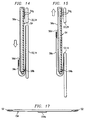
- Fig. 14 is a generally schematic view of a side edge of a bridge assembly and latch having the slide rails and bridge plate of Figs. 2 to 13, showing the assembly in the retracted position of the luggage item;
- Fig. 15 is a generally schematic view of a side edge of a bridge assembly and latch having the slide rails and bridge plate of Figs. 2 to 13, showing the assembly in the expanded position of the luggage item;
- Fig. 16 is a front plan view of another bridge assembly useful for the present invention, showing the assembly in the retracted position of the luggage item;
- Fig. 17 is a view of the top edge of the bridge assembly of Fig. 16;
- Fig. 18 is a front plan view of the bridge assembly of Figs. 16 and 17, showing it in the expanded state;
- Fig. 19 is a front plan view of yet another bridge assembly useful for the present invention, showing the assembly in the retracted position of the luggage item; and
- Fig. 20 is a front plan view of the bridge assembly of Fig. 19, showing it in the expanded state. DESCRIPTION OF THE EMBODIMENT
-
- The embodiment shown in Fig. 1 has a two-component frame, which may be of any suitable specific construction in terms of materials, manner of assembly, and configurations of the parts. A
main frame component 10 has a pair of rectangular planarside wall panels bottom wall member 16 and atop wall member 18, which are substantially rigid and rigidly connected at the corners. Although the drawing shows the bottom and top members as panels, most travel luggage being marketed currently is of the towable, wheeled type. In practice for such luggage items, the bottom member and top member of the main frame are configured to accept wheels, a towing handle, a carrying handle, and the like. Themain frame component 10 may also have a partial or complete rigid back wall panel. Asecondary frame component 20 is formed of opposite rectangularplanar panels 22 and 24 and top andbottom members - The
main frame component 10 receives acover 30 of a durable fabric. The sides, top and bottom of the secondary frame receive afabric cover 32. Access to the interior of the luggage item is through a front opening that is closed by apanel 34, is joined to thecover 32 along one edge and can be opened and closed by undoing and doing up azipper 36 that extends along three edges. - The main part (
main frame 10 and its cover 30) of the luggage item is joined to the secondary part (secondary frame 20 and itscover 32, 34) by agusset 36 of a durable, flexible material that extends along the entire perimeter of the luggage item (along the top, bottom and both side walls). In the expanded state of the item, thegusset 36 peripherally bounds that part of the entire volume of the main compartment by which the volume of the item is increased upon movement of the secondary unit away from the main unit. In the retracted (smaller volume) state (not shown) of the luggage item, azipper 40 that extends about the entire perimeter of the item is done up. Thegusset 36 folds into the interior of the item. - The
main frame component 10 is joined to thesecondary frame component 20 by twoidentical bridge assemblies 50, one of which is associated with theside panels 12 and 22 and the other with theside panels wall panel main frame component 10, a substantiallyrigid bridge plate 54 that is affixed to thewall panel 22, 24 of thesecondary frame component 20 and is slidably received by the slide rails 52, and a latch 56 (shown schematically as an arrow in Fig. 1) that releasably connects thebridge plate 54 to thewall panel main frame component 10 in at least one position in which thesecondary frame component 20 is held spaced apart from themain frame component 10, thereby to retain the luggage item in the expanded state. - A
suitable slide rail 52, as shown in Figs. 2 to 6, is injection molded from a durable polymeric material and has abody portion 52a with countersunkholes 52b for screws or rivets by which it is fastened to thewall panel flange portion 52c with arib 52d. The underside of thebody portion 52a bears against the surface of thepanel 12, 14 (or a fabric liner within the luggage item). Theflange portion 52c forms with thewall panel 12, 14 a guide groove that accepts the edge of the panel in sliding/guiding relation. - A
suitable bridge panel 54, as shown in Figs. 7 to 11, is injection molded from a durable polymeric material and has arecess 54a on the side facing into the interior of the luggage item, aslot 54b adjacent one edge, holes 54c for screws or rivets by which it is fastened to thewall panels 22, 24 of thesecondary frame component 20, andedge flanges 54d withribs 54e along each side edge. Thebottom edge 54f is smoothly rounded. Rows of tiny fabric anchor pins 54g protrude from the back surface near the upper edge. The guiding/sliding relationship between the slide rails 52 and bridge plate is shown in Figs. 12 and 13. - Many forms of latch can be used to releasably connect the bridge plate to the main
frame wall panels bridge plate 54 of Figs. 7 to 11 is designed for thelatch 56 shown in Figs. 14 and 15, the showing being schematic for greater clarity. Apiece 56a of a loop material, such as "VELMAT," is hemmed along one end to form a bead 45b, inserted through theslot 54b in thebridge panel 54, trained along the front of the bridge panel and folded over the top of the bridge panel. When thebridge panel 54 is fastened to thewall panel 22, 24, theloop piece 54a is clamped in place; the hem/bead holds the lower edge, and the clamping, along with thetiny pins 54g, holds the upper edge. Other ways of fastening theloop piece 56a to thebridge plate 54 are, of course, possible. Theloop piece 56a is received in therecess 54a of thebridge panel 54. - A
piece 56c of smooth strong flexible material is suitably fastened to themain wall panel secondary wall panel 22, 24, turned around the roundedbottom edge 54f of the bridge panel and guided freely along the front face of the bridge panel. Astrip 56d of hook cloth stitched to the free end of thepiece 56c is releasably anchored to theloop piece 56a at any desired location by the mutual tenacity of the loop and hook materials. The user may easily and quickly adjust the luggage item to any of an infinite number of volumes within the range of the smallest volume with thezipper 40 done up to the largest with thezipper 40 undone and thegusset 36 fully extended by grasping the ends of thepieces 56c of bothbridge assemblies 50 and pulling them toward the open front of the item. Pulling on thepieces 56c draws thepieces 56c around thelower edge 54f of thebride panel 54 and moves thesecondary frame 20 away from the main frame. At any desired point of movement, the user may anchor the hook strips 56d to theloop piece 56a, thereby setting the volume of the luggage item to the directed size. - In all positions of the latch assembly, and especially at the largest volume, the bridge assembly stabilizes the shape of the luggage item by preventing up and down movements, side to side movements, rotational skewing movements, and side to side and front to back cocking movements of the secondary unit relative to the main unit. More simply put, the sliding support of the
bridge plate 54 by the slide rails 52 holds the secondary unit stationary laterally, longitudinally and rotationally relative to the main unit in the plane of the rear edge of the secondary frame and maintains the plane of the rear edge of the secondary unit parallel to the plane of the front edge of the main unit. Thelatch 56 keeps the luggage item from collapsing. If the luggage item is adjusted to less than the maximum volume, the latch does not preclude movement of the secondary unit to the maximum volume position. Such movement is not of concern. The purpose of the latch is to maintain a desired minimum volume in an expanded state for the convenience of the user when he or she is packing the luggage and to avoid crushing the contents when the luggage is handled or stowed for transport. - Another
bridge assembly 150, as shown in Figs. 16 to 18, has a slightly modifiedbridge plate 154 and a push-button catch unit 156. Thebridge plate 154 has a recess (not shown per se but apparent from the front as aprotuberance 154a) in the rear surface that accepts thecatch unit 156 in the retracted state (Fig. 16). Apush button 156a of the catch unit is resiliently biased relative to the casing 156b of the catch unit such that in the expanded state of the luggage item it engages arounded edge 154b of the bridge panel at the lower edge of the recess/protuberance 156a, thus latching the luggage item in the expanded state (Fig. 18). The front face of the push button is tapered so that when the user pulls the secondary unit away from the main unit from the retracted position, the lower edge of ahole 154c in the recess/protuberance 154a cams the push button against its resiliency, so the user does not have to push the push buttons to expand the luggage item. Pushing in on therelease button 156a disengages the button from theshoulder 154b, allowing the luggage item to be restored from the expanded state (Fig. 18) to the retracted state (Fig. 16). - A
bridge assembly 250 that is based on a cam latch, as shown in Figs. 19 and 20, includes a modifiedbridge plate 254, which has acam hole 254a, and acam disc 256, which is pivotally attached by ascrew 256a (or rivet) to the mainframe wall panel bridge plate 254. An arcuatecam follower rib 256b that protrudes from the back face of thecam disc 256 pushes thebridge plate 254 from the retracted state (Fig. 19) to the expanded state (Fig. 20) when a user manually rotates thecam disc 256 clockwise about thepivot screw 256a. Arib 256c on the front face of thecam disc 256 can be engaged by the user's fingers to facilitate rotating the cam disc. Aridge 254b in thecam hole 254a captures thecam follower rib 256b when the luggage item is in the expanded state. Attaining the expanded state requires a slight movement of the secondary unit to a position farther away from the main unit than the final expanded position.
Claims (9)
- An item of expandable luggage that includesa frame having a first substantially rigid component (10) and a second substantially rigid component (20), each of which includes a pair of opposite rectangular peripheral wall panels (12, 14; 22, 24) that together with another pair of peripheral wall members (16, 18; 26, 28) form the peripheral boundary of a variable volume enclosure and a generally rectangular area, anda peripherally continuous gusset (36) of flexible material connected between the perimeter wall panels and peripheral wall members of the two frame components,
characterized in thata bridge assembly (50, 150, 250) joining each wall panel (12, 14) of the first component (10) to a corresponding wall panel (22, 24) of the second component (20) in coplanar relation and for linear displacement of the two components toward and away from each other, each bridge assembly includinga pair of parallel spaced-apart slide rails (52) affixed to the wall panel (12, 14) of the first component (10),a substantially rigid bridge plate (54, 154, 254)affixed to the wall panel (22, 24) of the second component (20) and slidably received by the slide rails (52), anda releasable latch (56, 156, 256) connecting the bridge plate (54, 154, 254) to the wall panel (12, 14) of the first component (10) in at least one position in which the second component (20) is held spaced apart from the first component (10). - The item of luggage as claimed in claim 1, and further characterized in that the releasable latch (56) enables the bridge plate to be latched to the wall panel of the first component in a plurality of positions.
- The item of luggage as claimed in claim 2, and further characterized in that the releasable latch (56) enables the bridge plate to be latched to the wall panel of the first component in an infinite number of positions.
- The item of luggage as claimed in claim 3, and further characterized in that the releasable latch (56) includes a panel of loop material (56a) affixed to the bridge panel (54), a flexible band (56c) attached to the wall panel (12, 14) of the first component (10), and a strip of hook material (56d) affixed to the flexible band and releasably engageable with the panel of loop material on the bridge plate.
- The item of luggage as claimed in claim 1, and further characterized in that the releasable latch includes a cam cutout (254a) in the bridge plate (254) and a cam disc (256) carried for rotation by the wall panel of the first component.
- The item of luggage as claimed in claim 1, and further characterized in that the releasable latch includes a resiliently biased catch button (156a) carried by the wall panel (12, 14) of the first component (10) and an abutment edge (154a) on the bridge plate (154) engageable by the catch button.
- The item of luggage as claimed in claim 1, and further characterized in that each slide rail (52) includes a body portion (52a) engaging the wall panel (12, 14) of the first component and a projecting flange portion (52c) defining with the wall panel of the first component a guide groove.
- The item of luggage as claimed in claim 7, and further characterized in that the flange portion (52c) has a guide rib (52d) projecting toward the wall panel of the first component.
- The item of luggage as claimed in claim 8, and further characterized in that the bridge plate (54) has along opposite edges a guide groove (54d) receiving the guide rib (52D) on the flange portion (52c) of the slide rail.
Applications Claiming Priority (2)
| Application Number | Priority Date | Filing Date | Title |
|---|---|---|---|
| US433405 | 1999-11-03 | ||
| US09/433,405 US6220411B1 (en) | 1999-11-03 | 1999-11-03 | Expandable luggage |
Publications (2)
| Publication Number | Publication Date |
|---|---|
| EP1097654A2 true EP1097654A2 (en) | 2001-05-09 |
| EP1097654A3 EP1097654A3 (en) | 2004-03-24 |
Family
ID=23720035
Family Applications (1)
| Application Number | Title | Priority Date | Filing Date |
|---|---|---|---|
| EP00106808A Withdrawn EP1097654A3 (en) | 1999-11-03 | 2000-03-30 | Expandable luggage |
Country Status (3)
| Country | Link |
|---|---|
| US (1) | US6220411B1 (en) |
| EP (1) | EP1097654A3 (en) |
| JP (1) | JP2001128719A (en) |
Cited By (2)
| Publication number | Priority date | Publication date | Assignee | Title |
|---|---|---|---|---|
| EP1566328A3 (en) * | 2004-02-20 | 2007-07-18 | Bayerische Motoren Werke Aktiengesellschaft | Adjustable size side case for motorcycle |
| WO2015110769A1 (en) | 2014-01-27 | 2015-07-30 | Delsey | Variable-volume luggage item |
Families Citing this family (46)
| Publication number | Priority date | Publication date | Assignee | Title |
|---|---|---|---|---|
| US6305513B1 (en) * | 2000-11-14 | 2001-10-23 | Ting Cheng Co., Ltd. | Mechanism for supporting expandable pouch of luggage |
| US6408997B1 (en) * | 2001-02-21 | 2002-06-25 | Shou-Mao Chen | Structure for expanding holding capacity of luggage |
| US6561395B2 (en) * | 2001-03-06 | 2003-05-13 | Mona Lim | Collapsible back pack |
| US6390259B1 (en) * | 2001-05-02 | 2002-05-21 | Ting Cheng Co., Ltd. | Wheeled luggage with expandable body |
| DE10150055B4 (en) * | 2001-10-10 | 2004-03-04 | Bayerische Motoren Werke Ag | Motorcycle case or motorcycle with a motorcycle case attached to it |
| US6533087B1 (en) * | 2002-03-05 | 2003-03-18 | Shou Mao Chen | Structure for expanding the capacity of luggage |
| US20070158157A1 (en) * | 2002-03-06 | 2007-07-12 | Krulik Richard J | Expandable luggage with locking expansion mechanism |
| US6575272B1 (en) | 2002-03-06 | 2003-06-10 | Briggs & Riley Travelware Llc | Expandable luggage with locking expansion mechanism |
| US6595354B1 (en) | 2002-04-03 | 2003-07-22 | Tumi, Inc. | Luggage with low-profile hanger bracket |
| US6591950B1 (en) | 2002-04-03 | 2003-07-15 | Tumi, Inc. | Multiple expansion luggage item |
| US7021437B2 (en) * | 2003-06-27 | 2006-04-04 | Mohssen Ghiassi | Expandable luggage system |
| AU2004100214B4 (en) * | 2003-06-27 | 2005-02-03 | Landor & Hawa International Limited | Suitcase |
| US7086510B2 (en) * | 2003-09-25 | 2006-08-08 | Trg Group, L.L.C. | Expandable luggage and expansion mechanism |
| ES2377156T3 (en) * | 2003-10-21 | 2012-03-23 | Landor & Hawa International Limited | ARTICLE OF LUGGAGE. |
| US7281616B2 (en) * | 2004-08-23 | 2007-10-16 | Tumi, Inc. | Expandable luggage |
| US7228962B2 (en) * | 2004-12-15 | 2007-06-12 | Tumi, Inc. | Luggage with low-profile hanger bracket and harness |
| US20070045071A1 (en) * | 2005-08-15 | 2007-03-01 | Aaron Gorga | Baggage item with internal zippered expansion assembly |
| US7699149B2 (en) * | 2005-12-30 | 2010-04-20 | Shin-Fu Eiken Lin | Zipperless expansion system |
| US20070267262A1 (en) * | 2006-05-05 | 2007-11-22 | Jeffrey Sederoff | Multi-level expandable suitcase |
| BRPI0702293A2 (en) * | 2007-05-18 | 2009-01-13 | Villaca Francisco Jose Rocha Jr | adaptable luggage case for storing and carrying one or more fins with or without fins |
| US8540063B2 (en) * | 2007-10-22 | 2013-09-24 | Aaron LaTowsky | Wheeled luggage with extendable supportive tongue |
| US20090166138A1 (en) * | 2007-12-28 | 2009-07-02 | Aaron Gorga | Adjustable rotary expansion mechanism for frames of an article |
| US7861834B2 (en) * | 2007-12-28 | 2011-01-04 | Trg Accessories, L.L.C. | Retractable wheel system for towable baggage |
| US8276721B2 (en) * | 2009-06-01 | 2012-10-02 | Mark Nordstrom | Collapsible baggage and method of collapsing and expanding a baggage |
| US20110186398A1 (en) * | 2010-01-29 | 2011-08-04 | Heys (USA), Inc. | Hard-Sided Expandable Suitcase |
| US8479900B2 (en) * | 2011-01-12 | 2013-07-09 | Tumi, Inc. | Luggage expansion system |
| US9101186B2 (en) * | 2013-08-04 | 2015-08-11 | Wei-Hung Lai | Hard shell luggage case capable of expanding carrying capacity |
| MX2016005503A (en) * | 2013-10-28 | 2016-10-13 | Travel-Light Ltd | LUGGAGE CASE WITH WHEELS. |
| US9634386B2 (en) | 2015-01-19 | 2017-04-25 | Christopher C. Dundorf | Apparatus for safely securing radiation-transparent panels covering the antenna service bays of wireless telecommunication towers and methods of installing the same |
| EP3066949B1 (en) * | 2015-03-10 | 2019-07-03 | Victorinox Ag | Volume expansion element |
| US9648933B2 (en) | 2015-04-01 | 2017-05-16 | Abiboo Corp. | Multi-purpose modular travel and packaging bag |
| KR200480283Y1 (en) * | 2015-10-13 | 2016-05-04 | 이정현 | carrier for travel |
| US10219599B2 (en) | 2015-11-06 | 2019-03-05 | JRSK, Inc. | Hard-shell luggage systems |
| US10595608B2 (en) | 2015-11-06 | 2020-03-24 | JRSK, Inc. | Luggage system employing a telescopically-extendable handle and battery power supply assembly equipped with a semi-automatic battery power module ejection mechanism |
| WO2018125859A1 (en) * | 2016-12-30 | 2018-07-05 | Briggs And Riley Travelware, Llc | Adjustable expansion system for luggage and luggage having the same |
| US10349711B2 (en) * | 2017-03-16 | 2019-07-16 | C & C Luggage Manufacturing Co., Ltd. | Extendable luggage |
| CN108634517A (en) * | 2018-08-15 | 2018-10-12 | 南京机电职业技术学院 | A kind of deformation suitcase |
| CN109907449A (en) * | 2019-03-27 | 2019-06-21 | 新疆石河子职业技术学院(石河子市技工学校) | A kind of multi-function suitcase with anti-theft function |
| USD965974S1 (en) | 2019-08-21 | 2022-10-11 | JRSK, Inc. | Luggage |
| USD979939S1 (en) | 2019-08-21 | 2023-03-07 | JRSK, Inc. | Luggage |
| USD979938S1 (en) | 2019-08-21 | 2023-03-07 | JRSK, Inc. | Luggage |
| EP4069601A4 (en) | 2019-12-06 | 2024-01-03 | Rux Box Corporation | PORTABLE FOLDABLE MODULAR AND WATERPROOF STORAGE AND TRANSPORT SYSTEM |
| US10926580B1 (en) | 2020-06-16 | 2021-02-23 | Austra Lee Galloway | Apparatus and method for cleaning a roller brush |
| KR102782492B1 (en) * | 2020-08-19 | 2025-03-18 | 튜미 인코포레이티드 | Expandable Luggage |
| KR102327547B1 (en) * | 2020-08-25 | 2021-11-17 | 김건우 | Carrier bag with size adjustable |
| US12433381B2 (en) | 2022-07-15 | 2025-10-07 | United States Luggage | Push button expansion system for luggage |
Family Cites Families (12)
| Publication number | Priority date | Publication date | Assignee | Title |
|---|---|---|---|---|
| US672143A (en) * | 1900-03-22 | 1901-04-16 | Claude Boughner | Telescopic traveling-bag. |
| US764144A (en) * | 1903-03-07 | 1904-07-05 | Frank H Mcgowan | Telescopic grip. |
| US2079476A (en) * | 1936-04-06 | 1937-05-04 | Wolff Lise | Traveling or lady's handbag |
| US3450237A (en) | 1967-08-24 | 1969-06-17 | Dyke Herbert G | Expansible carrying case with band latch |
| US4356899A (en) * | 1980-10-20 | 1982-11-02 | H.I.T. Industries, Ltd. | Attache case including expansion gusset |
| US4773515A (en) | 1987-04-28 | 1988-09-27 | Skyway Luggage Company | Multi-compartment, expansible luggage bag |
| US4813520A (en) * | 1987-08-06 | 1989-03-21 | Lin Tri Ping | Externally and detachably framed collapsible baggage |
| US5080206A (en) | 1987-11-19 | 1992-01-14 | Tawil Abraham I | Attache case including expanding gusset |
| US4953673A (en) | 1989-07-17 | 1990-09-04 | Emilio Ambasz | Expandable luggage |
| US5671831A (en) | 1996-03-13 | 1997-09-30 | Chiu; Tai-Yung | Adjustable travel bag |
| US5749446A (en) * | 1996-04-10 | 1998-05-12 | Jet General Investment Company | Collapsible luggage piece and cart |
| US6021874A (en) * | 1998-04-24 | 2000-02-08 | Mainland Marketing, Inc. | Expandable bag with hinged stiffening member |
-
1999
- 1999-11-03 US US09/433,405 patent/US6220411B1/en not_active Expired - Lifetime
-
2000
- 2000-03-30 EP EP00106808A patent/EP1097654A3/en not_active Withdrawn
- 2000-03-31 JP JP2000136433A patent/JP2001128719A/en active Pending
Non-Patent Citations (1)
| Title |
|---|
| None |
Cited By (2)
| Publication number | Priority date | Publication date | Assignee | Title |
|---|---|---|---|---|
| EP1566328A3 (en) * | 2004-02-20 | 2007-07-18 | Bayerische Motoren Werke Aktiengesellschaft | Adjustable size side case for motorcycle |
| WO2015110769A1 (en) | 2014-01-27 | 2015-07-30 | Delsey | Variable-volume luggage item |
Also Published As
| Publication number | Publication date |
|---|---|
| EP1097654A3 (en) | 2004-03-24 |
| US6220411B1 (en) | 2001-04-24 |
| JP2001128719A (en) | 2001-05-15 |
Similar Documents
| Publication | Publication Date | Title |
|---|---|---|
| US6220411B1 (en) | Expandable luggage | |
| US7281616B2 (en) | Expandable luggage | |
| US7426985B2 (en) | Expandable luggage with locking expansion mechanism | |
| US6591950B1 (en) | Multiple expansion luggage item | |
| US4126213A (en) | Collapsible suitcase | |
| US5358082A (en) | Expandable luggage combining hardside and softside materials | |
| US4020930A (en) | Double action brief case | |
| US20060207697A1 (en) | Configurable travel accessory | |
| US20020023812A1 (en) | Soft-sided carrying case | |
| EP2710916A1 (en) | Expandable zipper structure for a luggage item | |
| US8522937B2 (en) | Business case with removable handle and wheel assembly | |
| US20090183961A1 (en) | Collapsible Bag Mounting Structure and Collapsible Bag Associated Therewith | |
| US20070058887A1 (en) | Easel back storage and carrying case | |
| WO1998007344A1 (en) | Removable handle assembly for luggage | |
| US7178567B2 (en) | Expandable bag | |
| US20080279483A1 (en) | Collapsible bag with a v-shaped zipper | |
| US8820498B2 (en) | Expandable suitcase | |
| US20060144663A1 (en) | Carrying bag with computer-holding insert | |
| WO2015095865A1 (en) | Storage assembly | |
| US4090593A (en) | Expansible container | |
| US6595354B1 (en) | Luggage with low-profile hanger bracket | |
| AU2010101318A4 (en) | Luggage Item for Tablet Computer | |
| US7228962B2 (en) | Luggage with low-profile hanger bracket and harness | |
| US10448717B2 (en) | Luggage with strap within expandable area | |
| EP3741249A1 (en) | Expandable luggage |
Legal Events
| Date | Code | Title | Description |
|---|---|---|---|
| PUAI | Public reference made under article 153(3) epc to a published international application that has entered the european phase |
Free format text: ORIGINAL CODE: 0009012 |
|
| AK | Designated contracting states |
Kind code of ref document: A2 Designated state(s): AT BE CH CY DE DK ES FI FR GB GR IE IT LI LU MC NL PT SE |
|
| AX | Request for extension of the european patent |
Free format text: AL;LT;LV;MK;RO;SI |
|
| PUAL | Search report despatched |
Free format text: ORIGINAL CODE: 0009013 |
|
| AK | Designated contracting states |
Kind code of ref document: A3 Designated state(s): AT BE CH CY DE DK ES FI FR GB GR IE IT LI LU MC NL PT SE |
|
| AX | Request for extension of the european patent |
Extension state: AL LT LV MK RO SI |
|
| AKX | Designation fees paid |
Designated state(s): AT BE CH CY DE DK ES FI FR GB GR IE IT LI LU MC NL PT SE |
|
| STAA | Information on the status of an ep patent application or granted ep patent |
Free format text: STATUS: THE APPLICATION IS DEEMED TO BE WITHDRAWN |
|
| 18D | Application deemed to be withdrawn |
Effective date: 20040925 |