EP1097289B1 - Multi-line back pressure control system - Google Patents
Multi-line back pressure control system Download PDFInfo
- Publication number
- EP1097289B1 EP1097289B1 EP99933054A EP99933054A EP1097289B1 EP 1097289 B1 EP1097289 B1 EP 1097289B1 EP 99933054 A EP99933054 A EP 99933054A EP 99933054 A EP99933054 A EP 99933054A EP 1097289 B1 EP1097289 B1 EP 1097289B1
- Authority
- EP
- European Patent Office
- Prior art keywords
- hydraulic
- valve
- check
- check valve
- valves
- Prior art date
- Legal status (The legal status is an assumption and is not a legal conclusion. Google has not performed a legal analysis and makes no representation as to the accuracy of the status listed.)
- Expired - Lifetime
Links
- 239000012530 fluid Substances 0.000 claims description 67
- 238000004891 communication Methods 0.000 claims description 11
- 230000007246 mechanism Effects 0.000 claims description 7
- 238000011144 upstream manufacturing Methods 0.000 claims description 4
- 230000004888 barrier function Effects 0.000 description 12
- 230000009977 dual effect Effects 0.000 description 5
- 230000007774 longterm Effects 0.000 description 3
- 241000191291 Abies alba Species 0.000 description 2
- 238000007599 discharging Methods 0.000 description 2
- 229930195733 hydrocarbon Natural products 0.000 description 2
- 150000002430 hydrocarbons Chemical class 0.000 description 2
- 238000002955 isolation Methods 0.000 description 2
- 238000004519 manufacturing process Methods 0.000 description 2
- 239000002184 metal Substances 0.000 description 2
- 239000000126 substance Substances 0.000 description 2
- 239000004215 Carbon black (E152) Substances 0.000 description 1
- 230000015572 biosynthetic process Effects 0.000 description 1
- 238000011109 contamination Methods 0.000 description 1
- 230000007613 environmental effect Effects 0.000 description 1
- 238000005755 formation reaction Methods 0.000 description 1
- 230000002706 hydrostatic effect Effects 0.000 description 1
- 238000002347 injection Methods 0.000 description 1
- 239000007924 injection Substances 0.000 description 1
- 238000000034 method Methods 0.000 description 1
- 238000007789 sealing Methods 0.000 description 1
Images


Classifications
-
- F—MECHANICAL ENGINEERING; LIGHTING; HEATING; WEAPONS; BLASTING
- F15—FLUID-PRESSURE ACTUATORS; HYDRAULICS OR PNEUMATICS IN GENERAL
- F15B—SYSTEMS ACTING BY MEANS OF FLUIDS IN GENERAL; FLUID-PRESSURE ACTUATORS, e.g. SERVOMOTORS; DETAILS OF FLUID-PRESSURE SYSTEMS, NOT OTHERWISE PROVIDED FOR
- F15B13/00—Details of servomotor systems ; Valves for servomotor systems
- F15B13/01—Locking-valves or other detent i.e. load-holding devices
-
- E—FIXED CONSTRUCTIONS
- E21—EARTH OR ROCK DRILLING; MINING
- E21B—EARTH OR ROCK DRILLING; OBTAINING OIL, GAS, WATER, SOLUBLE OR MELTABLE MATERIALS OR A SLURRY OF MINERALS FROM WELLS
- E21B34/00—Valve arrangements for boreholes or wells
- E21B34/06—Valve arrangements for boreholes or wells in wells
- E21B34/10—Valve arrangements for boreholes or wells in wells operated by control fluid supplied from outside the borehole
Definitions
- the present invention relates to a system for controlling downhole well tools to produce hydrocarbons from a wellbore. More particularly, the invention relates to a back pressure control system providing safe operation in multiple hydraulic control lines.
- Downhole well tools control, select and regulate the production of hydrocarbon fluids and other fluids produced downhole from subterranean formations.
- Downhole well tools such as sliding sleeves, sliding side doors, interval control lines, safety valves, lubricator valves, chemical injection subs, and gas lift valves are representative examples of such tools.
- Well tools are typically controlled and powered from the wellbore surface by pressurizing hydraulic lines which extend from a Christmas Tree or other wellhead and into the wellbore lower end, see for example US-4,197,879.
- Dual pressure barriers in hydraulic lines are preferred to prevent hydraulic line failure during a wellbore catastrophic event.
- Dual pressure barrier systems have an active and a passive barrier.
- the active barrier typically comprises a valve located at the Christmas Tree or wellhead
- the passive barrier typically comprises a check valve located in the hydraulic line below the wellhead.
- the check valve restricts fluid flow in one direction as the hydraulic fluid, chemicals or other fluids are pumped downhole into the hydraulic line.
- the fluids pressurize an actuator in a single operation or are discharged into the tubing or wellbore annulus through an exit port or valve.
- safety valves require fluid flow control in opposite directions.
- safety valves do not internally provide dual barrier capabilities because such barriers would resist two-way fluid flow. Because safety valves do not provide a passive well control barrier, significant design effort has been made to enhance the reliability of safety valve operation.
- Safety valves have been designed with metal-to-metal fittings, metal dynamic seals, rod -piston actuators, and other features designed to provide reliable operation during a catastrophic event in the wellbore.
- Other safety valves use springs, annulus fluid pressure, or tubing fluid pressure to provide the restoring force necessary to return the closure mechanism to the original position.
- Downhole well tool actuators generally comprise short term or long term devices.
- Short term devices include one shot tools and tools having limited operating cycles.
- Hydraulically operated systems have mechanical mechanisms with simple shear pins or complex mechanisms performing over multiple cycles.
- Actuation signals are provided through mechanical, direct pressure, pressure pulsing, electromagnetic, and other mechanisms.
- the control mechanism may involve simple mechanics, fluid logic controls, timers, or electronics.
- Motive force can be provided through springs, differential pressure, hydrostatic pressure, or locally generated mechanisms.
- Long term devices provide virtually unlimited operating cycles and are designed for operation through the well producing life.
- One long term device provides a fail safe operating capabilities which closes with spring powered force when the hydraulic line pressure is lost. Combination electrical and hydraulic powered systems have been developed for downhole use.
- Control for a downhole tool can be provided by connecting a single hydraulic line to a tool such as an internal control valve ("ICV") or a lubricator valve, and by discharging hydraulic fluid from the line end into the wellbore.
- a tool such as an internal control valve (“ICV") or a lubricator valve
- This technique has several limitations as the hydraulic fluid exits the wellbore because of differential pressures between the hydraulic line and the wellbore.
- the discharge of hydraulic fluid into the wellbore comprises an undesirable environmental discharge, and the fluid discharge risks backflow and particulate contamination in the hydraulic system.
- the setting depths are limited by the maximum pressure that a pressure relief valve can hold between the differential pressure between the control line pressure and the production tubing. All of these limitations effectively restrict single line hydraulic systems to relatively low differential pressure applications such as lubricator valves and sliding sleeves.
- a second hydraulic line can be installed to return hydraulic fluid to the wellbore surface through a closed loop.
- dual hydraulic lines provided tool operation in two directions.
- a manual control disable valve and a manual choke control valve controlled hydraulic fluid flow on either side of a piston head.
- two hydraulic lines controlled a lubricator valve during well test operations. In all of these tools, two hydraulic lines are inefficient because the additional hydraulic lines increase sealing problems and reduce the available space through packers and wellheads. Additionally, passive barrier protection for each hydraulic line is not possible because of the return fluid flow from the well tool to the surface.
- the system should be reliable, adaptable to different tool configurations and combinations, and should provide passive back flow containment for downhole well tools.
- the present invention provides an apparatus for providing back pressure control in at least two hydraulic lines extending downhole in a wellbore.
- the apparatus comprises a check valve engaged with each of the hydraulic lines in a closed initial position, wherein each of said check valves prevents pressurized fluid downhole of the check valves from moving upstream of the check valves, and hydraulic means operable with the fluid pressure in a hydraulic line to selectively open a check valve engaged with another of the hydraulic lines to permit two-way fluid communication through the check valve.
- the hydraulic means is further operable when the hydraulic line fluid pressure is reduced to return the check valve to the initial position.
- each check valve can comprise a pilot operated check valve, and the invention is applicable to three or more hydraulic lines.
- the hydraulic means can comprise a control valve or control valve combination having fewer valves than hydraulic lines.
- the apparatus can selectively open fluid flow through hydraulic lines extending between a wellbore surface and a downhole tool.
- the apparatus can comprise a check valve engaged with each hydraulic line in a closed initial position where each of the check valves prevents pressurized fluid downhole of the check valve from moving upstream of said check valve, a hydraulic means operable with the fluid pressure in a hydraulic line to selectively open a check valve engaged with another hydraulic line to permit two-way fluid communication through the check valve, and a controller engaged with the hydraulic lines for selectively pressurizing at least one of the hydraulic lines to operate said hydraulic means and to open a check valve engaged with another of the hydraulic lines.
- the present invention provides passive back pressure control in multiple hydraulic lines, and is adaptable to systems having two or more hydraulic lines.
- the invention facilitates the creation of hydraulic line systems providing control functions and power requirements for the actuation of downhole well tools.
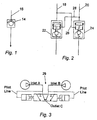
- Figure 1 illustrates the placement of conventional back check valve 14 in hydraulic fluid line 16.
- Hydraulic line 16 can extend from the wellbore surface to engagement located downhole in the wellbore. As illustrated, the direction of fluid flow can move in one direction and is prevented from flowing in the opposite direction.
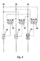
- Figure 2 illustrates the application of the invention to two hydraulic fluid lines 18 and 20, wherein pilot operated check valves 22 and 24 are integrated in fluid lines 18 and 20.
- Check valves 22 and 24 operate as conventional check valves to prevent fluid flow upwards from the lower end of fluid lines 18 and 20.
- pilot operated check valves 22 and 24 perform a different function when combined with another fluid pressure source.
- fluid line 18 When fluid line 18 is pressurized, fluid moves downwardly through check valve 22 and is further directed through line 26 to check valve 24 to open check valve 24 to two-way fluid flow.
- fluid line 20 moves fluid downwardly through check valve 24 and is further directed through line 28 to open check valve 22 to provide two-way fluid flow.
- the pilot function for valve 24 is removed and valve 24 closes to provide a passive pressure barrier.
- the pilot function for valve 22 is removed and valve 22 closes to provide a passive pressure barrier.
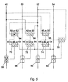
- valve 29 for providing control over the pressure communication or flow of fluid from multiple lines.
- FIG 3 One such valve is illustrated in Figure 3, wherein three-way, three-position piloted valve 29 has two positions and three ports. Two ports comprise inlet ports and the third comprises an outlet port. An internal, free floating check ball senses flow and pressure from the two inlet ports and closes the lessor flow inlet port in favor of the greater flow inlet port.
- shuttle valve 29 automatically provides a switching function between multiple lines without requiring electrically operated solenoid valves, additional hydraulic lines, electronic controls, or other combinations conventionally used.
- Different combinations of pilot activated check valves and hydraulic switching valves such as shuttle valve 29 can be connected in series or in parallel in various configurations and combinations to accomplish different operating functions. This combination provides unique flexibility in providing back pressure control in complex hydraulic operating systems.
- Figure 4 illustrates a three hydraulic line system wherein pilot check valves 30, 32 and 34 are integrated with hydraulic lines 36, 38 and 40 to provide passive back pressure control.
- Non-selective valves 42, 44 and 46 are integrated into the system to selectively provide the pilot function for check valves 30, 32 and 34.
- Pressurization of line 36 opens check valve 30 and further operates valve 44 to open check valve 32, and operates valve 46 to open check valve 34. Release of the pressure for line 36 causes check valves 30, 32 and 34 to close lines 36, 38 and 40.
- pressurization of line 38 opens check valve 32, operates valve 42 to open check valve 30, and further operates valve 46 to open check valve 34. Release of the pressure for line 38 causes check valves 30, 32 and 34 to close lines 36, 38 and 40.
- Pressurization of line 40 accomplishes a similar function of opening lines 36, 38 and 40.
- the dual pressurization of two lines such as lines 36 and 38 opens check valves 30 and 32 and operates valve 46 to open check valve 34 because pressure from line 36 or line 38 will move through valve 46 to open check valve 34.
- Figure 5 illustrates another embodiment of the invention applied to a four line system having lines 48, 50, 52 and 54, check valves 56, 58, 60 and 62, and valves 64, 66, 68, 70, 72, 74 and 76.
- Pressurization of line 48 opens check valve 56, operates valve 66 to operate valve 72 to open check valve 58, operates valve 68 to operate valve 74 to open check valve 60 and to operate valve 76 to open check valve 62.
- the pressurization of line 48 opens all four check valves 56, 58, 60 and 62.
- FIG. 6 illustrates another combination of components for a three line isolation system to selectively open and close lines 36, 38 and 40 with check valves 30, 32 and 34.
- Valves 78 and 80 provide the functional operation provided by the three valves identified in Figure 4. Valves 78 and 80 provide a package for simultaneously opening check valves 30, 32 and 34.
- line 36 or line 38 is pressurized, such hydraulic fluid line pressure operates valve 78 to operate valve 80 to open the check valves.
- valve 80 is operated to open the check valves.
- Figure 7 illustrates another embodiment of a four line isolation system to selectively open and close lines 48, 50, 52 and 54 with check valves 56, 58, 60 and 62.
- Valves 82, 84, and 86 provide the functional operation provided by the seven similar valves shown in Figure 5.
- line 48 or line 50 is pressurized, such line pressure operates valve 82 to operate valve 84 and to operate valve 86 to open check valves 56, 58, 60 and 62.
- valve 84 operates valve 86 to open the check valves.
- valve 86 is operated to open the check valves.
- the invention is particularly suited to systems requiring hydraulic fluid reliability to the control of downhole well tools by uniquely utilizing hydraulics with logic circuitry.
- logic circuitry is analogous to electrical and electronics systems, and can incorporate Boolean Logic using "AND” and “OR” gate combinations.
- the invention is particularly suitable for use with digital-hydraulic control systems serving multiple well control devices.
- pressure is applied in a coded sequence to several hydraulic lines.
- the coded sequence automatically selects one of the well control devices and provides independent operation of the well control device.
- excess fluid is returned up one of the unpressurized hydraulic lines.
- a system must permit such return flow through one or more hydraulic lines, and this return flow is provided by controlling the opening of the pilot operated check valves.
- the invention provides passive back check valves on each hydraulic line. If one or more of the lines are pressurized from the wellbore surface, the back check valves in the unpressurized lines are temporarily opened with pilot pistons activated by the pressurized lines. In this configuration, the passive barriers provided by the back check valves are temporarily opened for two-way fluid communication to permit single tool operation or to permit selected tool operation for different combinations. After the pressure in a hydraulic line is removed and the line pressure is bled down or otherwise reduced, the back check valve on such hydraulic line closes to prevent fluid flow in such direction. Passive back pressure control is maintained because pressure from below does not open the back check valve, and the piloting pressure to open the back check valves is only provided by hydraulic line pressure above the valve.
Landscapes
- Engineering & Computer Science (AREA)
- Geology (AREA)
- Fluid Mechanics (AREA)
- Mining & Mineral Resources (AREA)
- Physics & Mathematics (AREA)
- Life Sciences & Earth Sciences (AREA)
- General Engineering & Computer Science (AREA)
- Environmental & Geological Engineering (AREA)
- Mechanical Engineering (AREA)
- General Life Sciences & Earth Sciences (AREA)
- Geochemistry & Mineralogy (AREA)
- Fluid-Pressure Circuits (AREA)
- Operation Control Of Excavators (AREA)
- Electrical Discharge Machining, Electrochemical Machining, And Combined Machining (AREA)
- Push-Button Switches (AREA)
- Transplanting Machines (AREA)
Description
Claims (18)
- An apparatus for providing back pressure control in at least two hydraulic lines (18,20; 36, 38,40; 48,50,52,54) extending downhole in a wellbore, comprising:a check valve (22,24; 30,32,34; 56,58,60,62) engaged with each of the hydraulic lines (18,20; 36, 38,40; 48,50,52,54) in a closed initial position, wherein each of said check valves (22,24; 30,32,34; 56,58,60,62) prevents pressurized fluid downhole of said check valves (22,24; 30,32,34; 56,58,60,62) from moving upstream of said check valves (22,24; 30,32,34; 56,58,60,62); andhydraulic means (26,28; 29; 42,44,46; 64,66,68,70,72,74,76; 78,80; 82,84,86) operable with the fluid pressure in one of said hydraulic lines (18,20; 36, 38,40; 48,50,52,54) to selectively open a check valve (22,24; 30,32,34; 56,58,60,62) engaged with another of the hydraulic lines (18,20; 36, 38,40; 48,50,52,54) to permit two-way fluid communication through said check valve (22,24; 30,32,34; 56,58,60,62), wherein said hydraulic means (26,28; 29; 42,44,46; 64,66,68,70,72,74,76; 78,80; 82,84,86) is further operable when said hydraulic line fluid pressure is reduced to return said check valve (22,24; 30,32,34; 56,58,60,62) to said initial position.
- An apparatus as recited in Claim 1, wherein each check valve (22,24; 30,32,34; 56,58,60,62) comprises a pilot operated check valve (22,24; 30,32,34; 56,58,60,62).
- An apparatus as recited in either of Claims 1 or 2, wherein said hydraulic means (26,28; 29; 42,44,46; 64,66,68,70,72,74,76; 78,80; 82,84,86) comprises a pilot mechanism for each of said check valves (22,24; 30,32,34; 56,58,60,62).
- An apparatus as recited in any preceding Claim, wherein increased fluid pressure in a hydraulic line (18,20; 36, 38,40; 48,50,52,54) further opens the check valve (22,24; 30,32,34; 56,58,60,62) engaged with such hydraulic line (18,20; 36, 38,40; 48,50,52,54) to permit two-way communication through said check valve (22,24; 30,32,34; 56,58,60,62).
- An apparatus as recited in any preceding Claim, further comprising at least three check valves (30,32,34; 56,58,60,62) each engaged with a separate hydraulic line (36,38,40; 48,50,52,54), and wherein said hydraulic means (42,44,46; 64,66,68,70,72,74, 76; 78,80; 82,84,86) comprises a control valve engaged with two of said hydraulic lines (36,38,40; 48,50,52,54) for selectively communicating fluid pressure in one of two hydraulic lines (36,38,40; 48,50,52,54) to open the check valve (30,32,34; 56,58,60,62) engaged with said third hydraulic line.
- An apparatus as recited in Claim 5, wherein said hydraulic means (42,44,46; 64,66,68,70,72,74, 76; 78,80; 82,84,86) comprises a first control valve (42; 64; 78; 82) engaged with the first (38; 50; 36) and second (40; 52; 38) hydraulic lines and with a second control valve (44; 66; 80; 84) engaged with the third hydraulic line (36; 48; 40; 54), and wherein said second control valve (44; 66; 80; 84) is operable in response to fluid pressure in the third hydraulic line (36; 48; 40; 54) to open all three check valves (30,32,34; 56,58,60,62), and wherein said second control valve (44; 66; 80; 84) is further operable in response to said first control valve (42; 64; 78; 82) to open all three check valves (30,32,34; 56,58,60,62).
- An apparatus as recited in any preceding Claim, wherein said hydraulic means (42,44,46; 64,66,68,70, 72,74,76; 78,80; 82,84,86) comprises two or more three-way three-position valves (29) each operable in response to fluid pressure from one of two hydraulic lines to engage and open one of said check valves for permitting two-way fluid communication through said check valve.
- An apparatus as recited in Claim 7, wherein each three-way three-position valve (29) is operable to open all of said check valves for permitting two-way fluid communication through said check valves.
- An apparatus as recited in any preceding Claim, wherein said hydraulic means (42,44,46; 64,66,68,70, 72,74,76; 78,80; 82,84,86) comprises at least three control valves (42,44,46; 64,66,68,70,72,74,76; 78,80; 82,84,86) each engaged with at least one hydraulic line (36,38,40; 48,50,52,54) and with at least one of said other control valves (42,44,46; 64,66,68,70,72,74,76; 78,80; 82,84,86), wherein each control valve (42,44,46; 64,66,68,70,72,74,76; 78,80; 82,84,86) is operable in response to fluid pressure from one of said hydraulic lines (36,38,40; 48,50,52,54) or other control valves (42,44,46; 64,66,68,70,72,74,76; 78,80; 82,84,86) to open at least one of said check valves (30,32,34; 56,58,60,62).
- An apparatus as recited in Claim 9, wherein one of said control valves (42,44,46; 64,66,68,70,72,74, 76; 78,80; 82,84,86) comprises a master control valve engaged with each hydraulic line (36,38,40; 48,50,52,54) and with each of said check valves (30,32,34; 56,58,60,62) so that hydraulic fluid pressure in one of the hydraulic lines (36,38,40; 48,50,52,54) is transmitted through said master control valve to open all of said check valves (30,32,34; 56,58,60,62) for two-way fluid communication.
- An apparatus for selectively opening fluid flow through hydraulic lines (36,38,40; 48,50,52,54) extending between a wellbore surface and a downhole tool, comprising:a check valve (30,32,34; 56,58,60,62) engaged with each hydraulic line (36,38,40; 48,50,52,54) in a closed initial position, wherein each of said check valves (30,32,34; 56,58,60,62) prevents pressurized fluid downhole of said check valve (30,32,34; 56,58,60,62) from moving upstream of said check valve (30,32,34; 56,58,60,62);hydraulic means (42,44,46; 64,66,68,70,72,74, 76; 78,80; 82,84,86) operable with the fluid pressure in a hydraulic line (36,38,40; 48,50,52,54) to selectively open a check valve (30,32,34; 56,58,60,62) engaged with another hydraulic line (36,38,40; 48,50,52,54) to permit two-way fluid communication through said check valve (30,32,34; 56,58,60,62); anda controller (29) engaged with the hydraulic lines for selectively pressurizing at least one of the hydraulic lines (36,38,40; 48,50,52,54) to operate said hydraulic means (42,44,46; 64,66,68,70,72,74,76; 78,80; 82,84,86) to open a check valve (30,32,34; 56,58,60,62) engaged with another of the hydraulic lines (36,38,40; 48,50,52,54).
- An apparatus as recited in Claim 11, wherein each check valve (30,32,34; 56,58,60,62) comprises a back flow device having an override.
- An apparatus as recited in either of Claims 11 or 12, wherein said hydraulic means (42,44,46; 64,66,68,70,72,74,76; 78,80; 82,84,86) comprises an override engaged with each of said check valves (30,32,34; 56,58,60,62).
- An apparatus as recited in any of Claims 11 to 13, wherein said hydraulic means (42,44,46; 64,66,68,70,72,74,76; 78,80; 82,84,86) is configured to open each check valve (30,32,34; 56,58,60,62) by the operation of said controller (29) to pressurize a selected hydraulic line (36,38,40; 48,50,52,54).
- An apparatus as recited in any of Claims 11 to 14, wherein said hydraulic means (42,44,46; 64,66, 68,70,72,74,76; 78,80; 82,84,86) is configured to open a selected combination of check valves (30,32,34; 56,58,60,62) by the operation of said controller (29) to pressurize a selected hydraulic line (36,38,40; 48,50,52,54).
- An apparatus as recited in any of Claims 11 to .15, wherein said hydraulic means (42,44,46; 64,66, 68,70,72,74,76; 78,80; 82,84,86) is configured to open each check valve (30,32,34; 56,58,60,62) by the pressurization of one hydraulic line (36,38,40; 48,50,52,54).
- An apparatus as recited in Claim 16, wherein said hydraulic means (42,44,46; 64,66,68,70,72,74, 76; 78,80; 82,84,86) is configured so that the pressurization of each hydraulic line (36,38,40; 48,50,52,54) independently opens all of said check valves (30,32,34; 56,58,60,62) to two-way fluid communication.
- An apparatus as recited in any of Claims 11 to 17, wherein said controller (29) is operable to withdraw pressurization of said hydraulic lines (36,38,40; 48,50,52,54) to return each of said check valves (30,32,34; 56,58,60,62) to said closed initial position.
Applications Claiming Priority (3)
| Application Number | Priority Date | Filing Date | Title |
|---|---|---|---|
| US115889 | 1998-07-15 | ||
| US09/115,889 US6659184B1 (en) | 1998-07-15 | 1998-07-15 | Multi-line back pressure control system |
| PCT/GB1999/002283 WO2000004273A1 (en) | 1998-07-15 | 1999-07-15 | Multi-line back pressure control system |
Publications (2)
| Publication Number | Publication Date |
|---|---|
| EP1097289A1 EP1097289A1 (en) | 2001-05-09 |
| EP1097289B1 true EP1097289B1 (en) | 2004-05-26 |
Family
ID=22363992
Family Applications (1)
| Application Number | Title | Priority Date | Filing Date |
|---|---|---|---|
| EP99933054A Expired - Lifetime EP1097289B1 (en) | 1998-07-15 | 1999-07-15 | Multi-line back pressure control system |
Country Status (7)
| Country | Link |
|---|---|
| US (1) | US6659184B1 (en) |
| EP (1) | EP1097289B1 (en) |
| AU (1) | AU757656B2 (en) |
| BR (1) | BR9912056A (en) |
| CA (1) | CA2337337C (en) |
| NO (1) | NO322384B1 (en) |
| WO (1) | WO2000004273A1 (en) |
Families Citing this family (29)
| Publication number | Priority date | Publication date | Assignee | Title |
|---|---|---|---|---|
| US7182139B2 (en) | 2002-09-13 | 2007-02-27 | Schlumberger Technology Corporation | System and method for controlling downhole tools |
| US7147054B2 (en) | 2003-09-03 | 2006-12-12 | Schlumberger Technology Corporation | Gravel packing a well |
| US7208845B2 (en) * | 2004-04-15 | 2007-04-24 | Halliburton Energy Services, Inc. | Vibration based power generator |
| US7273107B2 (en) * | 2004-06-10 | 2007-09-25 | Schlumberger Technology Corporation | Valve within a control line |
| ATE542026T1 (en) * | 2005-02-08 | 2012-02-15 | Welldynamics Inc | FLOW REGULATOR FOR USE IN AN UNDERGROUND BORE |
| CA2596399C (en) | 2005-02-08 | 2010-04-20 | Welldynamics, Inc. | Downhole electrical power generator |
| WO2006130140A1 (en) * | 2005-05-31 | 2006-12-07 | Welldynamics, Inc. | Downhole ram pump |
| WO2007021274A1 (en) | 2005-08-15 | 2007-02-22 | Welldynamics, Inc. | Pulse width modulated downhole flow control |
| US8291979B2 (en) * | 2007-03-27 | 2012-10-23 | Schlumberger Technology Corporation | Controlling flows in a well |
| US7814976B2 (en) * | 2007-08-30 | 2010-10-19 | Schlumberger Technology Corporation | Flow control device and method for a downhole oil-water separator |
| US8006757B2 (en) * | 2007-08-30 | 2011-08-30 | Schlumberger Technology Corporation | Flow control system and method for downhole oil-water processing |
| US8188881B2 (en) * | 2008-03-26 | 2012-05-29 | Schlumberger Technology Corporation | System and method for controlling multiple well tools |
| US7857061B2 (en) * | 2008-05-20 | 2010-12-28 | Halliburton Energy Services, Inc. | Flow control in a well bore |
| WO2011016813A1 (en) * | 2009-08-07 | 2011-02-10 | Halliburton Energy Services, Inc. | Annulus vortex flowmeter |
| US8210257B2 (en) | 2010-03-01 | 2012-07-03 | Halliburton Energy Services Inc. | Fracturing a stress-altered subterranean formation |
| US9719324B2 (en) * | 2012-02-17 | 2017-08-01 | Halliburton Energy Services, Inc. | Operation of multiple interconnected hydraulic actuators in a subterranean well |
| BR112016004028B1 (en) | 2013-10-28 | 2021-06-29 | Halliburton Energy Services, Inc | FLOW CONTROL ASSEMBLY, AND, ASSEMBLY TO CONTROL FLUID INJECTION FOR AN INJECTION MANDRIL |
| GB2520977B (en) * | 2013-12-05 | 2020-06-24 | Ge Oil & Gas Uk Ltd | Hydraulic flushing system |
| US9976387B2 (en) | 2014-04-29 | 2018-05-22 | Baker Hughes, A Ge Company, Llc | Selectively operated two way check valve for subterranean use |
| US9816626B1 (en) | 2014-07-15 | 2017-11-14 | Davis & Davis Company | Method and device for adapting an actuator to a valve |
| EP3088654A1 (en) * | 2015-04-30 | 2016-11-02 | Welltec A/S | Annular barrier with expansion unit |
| CA2996270C (en) * | 2015-10-12 | 2019-11-26 | Halliburton Energy Services, Inc. | Auto-shut-in chemical injection valve |
| CN105298453B (en) * | 2015-10-12 | 2018-03-09 | 中国石油天然气股份有限公司 | A hydraulic automatic pressure reduction device |
| US20170234091A1 (en) * | 2016-02-11 | 2017-08-17 | Baker Hughes Incorporated | Removable Control Line Barrier |
| BR112019021346B1 (en) * | 2017-06-21 | 2023-04-11 | Halliburton Energy Services Inc | CHEMICAL INJECTION AND PRODUCTION FLUID RECOVERY SYSTEMS |
| US11067106B2 (en) * | 2018-05-25 | 2021-07-20 | Schlumberger Technology Corporation | System for implementing redundancy in hydraulic circuits and actuating multi-cycle hydraulic tools |
| DE102018133206B3 (en) * | 2018-12-20 | 2020-03-26 | Hps Home Power Solutions Gmbh | Energy system and method for line pressure monitoring |
| US12480589B2 (en) | 2019-01-15 | 2025-11-25 | Prevco Subsea Llc | Pressure relief valve assembly including series coupled valves and related methods |
| US11473685B2 (en) | 2019-01-15 | 2022-10-18 | Prevco Subsea Llc | Dual poppet pressure relief valve with vacuum adaptor capability |
Family Cites Families (13)
| Publication number | Priority date | Publication date | Assignee | Title |
|---|---|---|---|---|
| US3568768A (en) * | 1969-06-05 | 1971-03-09 | Cook Testing Co | Well pressure responsive valve |
| US3850194A (en) * | 1973-01-09 | 1974-11-26 | Brown Oil Tools | Check valve assembly |
| US3906726A (en) | 1974-12-20 | 1975-09-23 | Halliburton Co | Positioner methods and apparatus |
| US4081053A (en) * | 1976-11-19 | 1978-03-28 | Terry McDermid | Lock valve for double acting cylinder |
| US4368871A (en) | 1977-10-03 | 1983-01-18 | Schlumberger Technology Corporation | Lubricator valve apparatus |
| US4197879A (en) | 1977-10-03 | 1980-04-15 | Schlumberger Technology Corporation | Lubricator valve apparatus |
| US4407183A (en) * | 1978-09-27 | 1983-10-04 | Fmc Corporation | Method and apparatus for hydraulically controlling subsea equipment |
| DE68928332T2 (en) * | 1988-01-29 | 1998-01-29 | Inst Francais Du Petrol | Method and device for hydraulically and optionally controlling at least two tools or instruments of a device, valve for performing this method or using this device |
| FR2626613A1 (en) | 1988-01-29 | 1989-08-04 | Inst Francais Du Petrole | DEVICE AND METHOD FOR PERFORMING OPERATIONS AND / OR INTERVENTIONS IN A WELL |
| EP0854748A2 (en) * | 1995-07-27 | 1998-07-29 | Pall Corporation | Hybrid filter system and method for filtering process fluid |
| AU3390397A (en) * | 1996-06-13 | 1998-01-07 | Pes, Inc. | Downhole lubricator valve |
| NO306033B1 (en) * | 1998-06-05 | 1999-09-06 | Ziebel As | Device and method for independently controlling control devices for regulating fluid flow between a hydrocarbon reservoir and a well |
| US6247536B1 (en) * | 1998-07-14 | 2001-06-19 | Camco International Inc. | Downhole multiplexer and related methods |
-
1998
- 1998-07-15 US US09/115,889 patent/US6659184B1/en not_active Expired - Lifetime
-
1999
- 1999-07-15 BR BR9912056-9A patent/BR9912056A/en not_active IP Right Cessation
- 1999-07-15 CA CA002337337A patent/CA2337337C/en not_active Expired - Fee Related
- 1999-07-15 WO PCT/GB1999/002283 patent/WO2000004273A1/en not_active Ceased
- 1999-07-15 EP EP99933054A patent/EP1097289B1/en not_active Expired - Lifetime
- 1999-07-15 AU AU49229/99A patent/AU757656B2/en not_active Ceased
-
2001
- 2001-01-12 NO NO20010206A patent/NO322384B1/en not_active IP Right Cessation
Also Published As
| Publication number | Publication date |
|---|---|
| US6659184B1 (en) | 2003-12-09 |
| EP1097289A1 (en) | 2001-05-09 |
| NO20010206D0 (en) | 2001-01-12 |
| WO2000004273A1 (en) | 2000-01-27 |
| BR9912056A (en) | 2001-09-25 |
| CA2337337A1 (en) | 2000-01-27 |
| NO322384B1 (en) | 2006-09-25 |
| NO20010206L (en) | 2001-03-12 |
| CA2337337C (en) | 2007-04-03 |
| AU4922999A (en) | 2000-02-07 |
| AU757656B2 (en) | 2003-02-27 |
Similar Documents
| Publication | Publication Date | Title |
|---|---|---|
| CA2337337C (en) | Multi-line back pressure control system | |
| US6179052B1 (en) | Digital-hydraulic well control system | |
| CA2440624C (en) | System and method for controlling downhole tools | |
| US5207272A (en) | Electrically actuated well packer | |
| US6427778B1 (en) | Control system for deep set subsurface valves | |
| US8360158B2 (en) | Overriding a primary control subsystem of a downhole tool | |
| US11053774B2 (en) | Tubing or annulus pressure operated borehole barrier valve | |
| CA1129339A (en) | Safety valve operating apparatus | |
| US8151887B2 (en) | Lubricator valve | |
| US4215748A (en) | Lockout for a well injection valve | |
| US4469179A (en) | Safety system | |
| CA2868556A1 (en) | Downhole zone flow control system | |
| WO2017118858A1 (en) | Downhole disconnect tool, downhole tool assembly and method | |
| EP0923690B1 (en) | Integrated power and control system | |
| WO1997047852A1 (en) | Downhole lubricator valve | |
| US4193449A (en) | Valve operating circuit |
Legal Events
| Date | Code | Title | Description |
|---|---|---|---|
| PUAI | Public reference made under article 153(3) epc to a published international application that has entered the european phase |
Free format text: ORIGINAL CODE: 0009012 |
|
| 17P | Request for examination filed |
Effective date: 20010202 |
|
| AK | Designated contracting states |
Kind code of ref document: A1 Designated state(s): AT BE CH CY DE DK ES FI FR GB GR IE IT LI LU MC NL PT SE |
|
| RAP1 | Party data changed (applicant data changed or rights of an application transferred) |
Owner name: WELLDYNAMIS INC. |
|
| RAP3 | Party data changed (applicant data changed or rights of an application transferred) |
Owner name: WELLDYNAMICS INC. |
|
| 17Q | First examination report despatched |
Effective date: 20020917 |
|
| GRAH | Despatch of communication of intention to grant a patent |
Free format text: ORIGINAL CODE: EPIDOS IGRA |
|
| GRAS | Grant fee paid |
Free format text: ORIGINAL CODE: EPIDOSNIGR3 |
|
| GRAA | (expected) grant |
Free format text: ORIGINAL CODE: 0009210 |
|
| AK | Designated contracting states |
Kind code of ref document: B1 Designated state(s): FR GB |
|
| RBV | Designated contracting states (corrected) |
Designated state(s): FR GB |
|
| REG | Reference to a national code |
Ref country code: GB Ref legal event code: FG4D |
|
| REG | Reference to a national code |
Ref country code: IE Ref legal event code: FG4D |
|
| REG | Reference to a national code |
Ref country code: DE Ref legal event code: 8566 |
|
| ET | Fr: translation filed | ||
| PLBE | No opposition filed within time limit |
Free format text: ORIGINAL CODE: 0009261 |
|
| STAA | Information on the status of an ep patent application or granted ep patent |
Free format text: STATUS: NO OPPOSITION FILED WITHIN TIME LIMIT |
|
| REG | Reference to a national code |
Ref country code: IE Ref legal event code: MM4A |
|
| 26N | No opposition filed |
Effective date: 20050301 |
|
| PGFP | Annual fee paid to national office [announced via postgrant information from national office to epo] |
Ref country code: FR Payment date: 20080718 Year of fee payment: 10 |
|
| PGFP | Annual fee paid to national office [announced via postgrant information from national office to epo] |
Ref country code: GB Payment date: 20080716 Year of fee payment: 10 |
|
| GBPC | Gb: european patent ceased through non-payment of renewal fee |
Effective date: 20090715 |
|
| REG | Reference to a national code |
Ref country code: FR Ref legal event code: ST Effective date: 20100331 |
|
| PG25 | Lapsed in a contracting state [announced via postgrant information from national office to epo] |
Ref country code: FR Free format text: LAPSE BECAUSE OF NON-PAYMENT OF DUE FEES Effective date: 20090731 |
|
| PG25 | Lapsed in a contracting state [announced via postgrant information from national office to epo] |
Ref country code: GB Free format text: LAPSE BECAUSE OF NON-PAYMENT OF DUE FEES Effective date: 20090715 |