EP1096761A2 - Communication system via first communication line with a first communication apparatus and via a second communication line with a second communication apparatus - Google Patents
Communication system via first communication line with a first communication apparatus and via a second communication line with a second communication apparatus Download PDFInfo
- Publication number
- EP1096761A2 EP1096761A2 EP00309358A EP00309358A EP1096761A2 EP 1096761 A2 EP1096761 A2 EP 1096761A2 EP 00309358 A EP00309358 A EP 00309358A EP 00309358 A EP00309358 A EP 00309358A EP 1096761 A2 EP1096761 A2 EP 1096761A2
- Authority
- EP
- European Patent Office
- Prior art keywords
- communication
- communication apparatus
- line
- input means
- information
- Prior art date
- Legal status (The legal status is an assumption and is not a legal conclusion. Google has not performed a legal analysis and makes no representation as to the accuracy of the status listed.)
- Granted
Links
Images



Classifications
-
- H—ELECTRICITY
- H04—ELECTRIC COMMUNICATION TECHNIQUE
- H04M—TELEPHONIC COMMUNICATION
- H04M1/00—Substation equipment, e.g. for use by subscribers
- H04M1/72—Mobile telephones; Cordless telephones, i.e. devices for establishing wireless links to base stations without route selection
- H04M1/725—Cordless telephones
-
- H—ELECTRICITY
- H04—ELECTRIC COMMUNICATION TECHNIQUE
- H04M—TELEPHONIC COMMUNICATION
- H04M1/00—Substation equipment, e.g. for use by subscribers
- H04M1/60—Substation equipment, e.g. for use by subscribers including speech amplifiers
- H04M1/6033—Substation equipment, e.g. for use by subscribers including speech amplifiers for providing handsfree use or a loudspeaker mode in telephone sets
- H04M1/6041—Portable telephones adapted for handsfree use
Definitions
- the present invention relates to a communication system having a first communication apparatus capable of communication via a first communication line and a second communication apparatus capable of communication via a second communication line, and to communication apparatus used for the system.
- Wireless portable telephones and personal handy-phone system (PHS) telephones are greatly prevailing nowadays, and some people have telephones more than one.
- a user can hold a wireless telephone in hand and can make a telephone conversation anywhere and anytime. It is a great convenience for a user to have such a telephone.
- facsimile apparatus which are typical communication apparatus connectable to a public telephone line.
- the future use of a facsimile apparatus is considered not to be lowered, because an original image or text can be easily transmitted or received.
- Household telephones are being increasingly replaced by facsimile apparatus which are provided with a hands-free talking function and an automatic answering telephone. Acoustic components used with a facsimile apparatus having the hands-free talking function have good characteristics. A dedicated echo canceler is also built in a facsimile apparatus.
- a wireless portable telephone or PHS telephone used via a cell system base station is required to be compact and light in weight so as to facilitate to hold it outdoors.
- a compact and light telephone is easy to use. Namely, a compact telephone uses a compact speaker so that the sound volume is small and the sound quality is poor, and the sensitivity of the microphone is low. Therefore, it is necessary to use the microphone and speaker set near at a user, and the so-called hands-free talking is difficult.
- a small telephone has a small battery in order to reduce the weight of the telephone. If a large sound is reproduced or an echo canceler is driven for the hands-free talking, a large current flows and the battery is consumed greatly. A speech time or a standby time may be shortened. Such a telephone is not therefore suitable for indoor use.
- the description will be given for the embodiments of the invention including a wireless telephone apparatus, a communication apparatus, a wireless talking method, and a storage medium.
- the wireless telephone apparatus is applied to a PHS (Personal Handy-phone System) telephone in Japan and the communication apparatus is applied to a facsimile apparatus.
- PHS Personal Handy-phone System
- Figs. 1A and 1B are schematic diagrams showing the structures of a wireless telephone apparatus and a facsimile apparatus according to the embodiment of the invention.
- the facsimile apparatus 101 has a connection unit 102 for the connection to the wireless telephone apparatus 103.
- This connection unit 102 may be built in the facsimile apparatus 101 or detachably mounted on the facsimile apparatus 101.
- the facsimile apparatus 101 is connectable to a radio channel (wireless line) via the wireless telephone apparatus 103 or to a wire channel such as a PSTN channel and an ISDN channel.
- the wireless telephone apparatus 103 has a connection unit (corresponding to a connector 213 shown in Fig. 2).
- Fig. 1A shows the state that the wireless telephone apparatus 103 is not connected to the facsimile apparatus 101.
- This state corresponds to the state that the wireless telephone apparatus 103 is connected to a radio channel 104 and can have a telephone conversation over the radio channel 104.
- a speaker 105 and a microphone 106 built in the wireless telephone apparatus 103 are used for the telephone conversation.
- Fig. 1B shows the state that the wireless telephone apparatus 103 is connected to the facsimile apparatus 101.
- This state corresponds to that the wireless telephone apparatus 103 functions as a wireless adapter and that the facsimile apparatus is connected to a radio channel 104 via the wireless telephone apparatus 103 and can have a telephone conversation.
- a speaker 107 and a microphone 108 built in the facsimile apparatus 101 are used for the telephone conversation.
- the radio system is PHS.
- Other similar radio systems may also be used.
- general wireless radio systems currently used such as a PDC system and a CDMA system including IMT 2000, may be used.
- Future radio systems to be developed may also be used.
- a DECT (Digital European Cordless Telephone) system or a GSM (Global System for Mobile Communications) system developed in Europe may also be used.
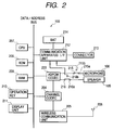
- Fig. 2 is a block diagram showing the structure of the wireless telephone apparatus 103.
- the wireless telephone apparatus 103 has a microphone 106, a speaker 105, an ADPCM codec 203, a channel codec 204, a wireless communication unit 205, key switches (operation keys) 210, a display unit 211, a CPU 207, a ROM 208, a RAM 209, a communication apparatus I/F unit 212, a connector 213, and a battery BAT 214.
- the microphone 106 receives sounds and outputs a sound signal.
- the ADPCM codec 203 converts a sound signal input from the microphone 106 into an ADPCM code to transmit it over the radio channel, and converts a received ADPCM code into an analog voice signal to output it from the speaker 105.
- the channel codec 204 converts voice data and control data into data in conformity with a PHS communication system, and derives audio data from received data.
- the radio communication unit 205 has the antenna 206 and various electronic components, the antenna 206 being used for the connection to the radio channel 104 of a base station provided by a radio common carrier.
- the operation keys 210 have a plurality of key switches to be used for instructing each operation.
- the display unit 211 may be an LCD or an LED to be used for a user to confirm the state of the wireless telephone apparatus 103 or display other data.
- CPU 207 controls the whole of the wireless telephone apparatus (a child apparatus).
- ROM 208 stores programs and parameters to be used for controlling the whole of the wireless telephone apparatus, the programs being executed by CPU 207.
- RAM 209 temporarily stores parameters to be used for controlling the whole of the wireless telephone apparatus, and transmission/reception data.
- the battery (BAT) 214 is connected to the facsimile apparatus or communication apparatus to charge the battery, and used as the power source of the wireless telephone apparatus 103.
- the communication apparatus I/F unit 212 has a circuit for detecting whether the wireless telephone apparatus 103 is connected to the facsimile apparatus 101 and a control circuit for switching an output of an audio signal to the facsimile apparatus 101.
- the connector 213 establishes a physical connection (electrical connection) to the facsimile apparatus 101.
- Signal lines connected via the connector 213 include upstream and downstream audio signal lines, power source lines for charging the battery 214, and other lines.
- the switch 215 switches an audio signal input to the ADPCM codec 203 between the microphone 106 and connector 213 to transmit it via the radio channel.
- the switch 216 switches an output of an audio ADPCM code received via the radio channel between the speaker 105 and connector 213.
- Fig. 3 is a block diagram showing the structure of the facsimile apparatus 101.
- the facsimile apparatus 101 is designed so that it can be connected to the wireless telephone apparatus 103.
- the facsimile apparatus 101 has a CPU 301, a ROM 302, an operation panel 304, a reader unit 305, a recorder unit 306, a communication control unit 307, a microphone 108, a speaker 107, a handset 311, and a connection unit 102.
- CPU 301 controls the whole of the facsimile apparatus 101.
- ROM 302 stores control programs and parameters to be executed by CPU 301 and used for controlling the whole of the facsimile apparatus.
- RAM 303 stores parameters and data necessary for the operations of CPU 301 and facsimile apparatus 101, image data and data files to be transmitted and received, data of a character code format, and the like.
- the operation panel 304 is used for a user to instruct each operation of the facsimile apparatus 101 and is used for displaying the state of the facsimile apparatus 101.
- the reader unit 305 reads a facsimile transmission original or a copy original as a color image or a black/white image.
- the recorder unit 306 prints out a facsimile reception original or a copy original in color or black/white.
- the communication control unit 307 performs a control and transmission/reception of a facsimile communication protocol such as G3 and G4, a control of signal modulation/demodulation, a control of a line echo canceler and an acoustic echo canceler for hands-free talking, an off-hook control and an on-hook detection for a public telephone apparatus line 308 such as PSTN and ISDN, and the like.
- a facsimile communication protocol such as G3 and G4
- a control of signal modulation/demodulation a control of a line echo canceler and an acoustic echo canceler for hands-free talking
- an off-hook control and an on-hook detection for a public telephone apparatus line 308 such as PSTN and ISDN, and the like.
- the communication control unit 307 also has a function of switching analog upstream and downstream signals transferred via the connection unit 102 between the microphone 108 and speaker 107 of the facsimile apparatus, and supplying a signal transferred via the public telephone apparatus line 308 to the handset 311 during a normal talking mode or switching the signal between the microphone 108 and speaker 107 of the facsimile apparatus during a hands-free talking mode.
- the connection unit 102 has a wireless telephone apparatus I/F unit 309 and a connector 310.
- the wireless telephone apparatus I/F unit 309 is used for the interface with the wireless telephone apparatus 103 and has an audio signal connection circuit for receiving an audio signal from the wireless telephone apparatus 103, a power supply circuit for charging the battery BAT of the wireless telephone apparatus 103, and a circuit for detecting a connection of the wireless telephone apparatus 103.
- the connector 310 is physically (electrically) connected to the connector 213 of the wireless telephone apparatus 103. Signal lines connected via the connector 310 include upstream and downstream audio signal lines and power source lines for charging the battery of the wireless telephone apparatus 103.
- Input/output lines of the wireless telephone apparatus I/F unit 309 are connected by the communication control unit 307 to the line echo canceler and acoustic echo canceler for the hands-free talking mode, in order to receive radio waves of audio signals transmitted from the wireless telephone apparatus 103.
- connection units of the wireless telephone apparatus 103 and facsimile apparatus 101 will be described.
- the connector 213 connected to the communication apparatus I/F unit 212 of the wireless telephone apparatus 103 and the connector 310 connected to the wireless telephone apparatus I/F unit 309 of the facsimile apparatus 101 can be removably connected together.
- the signal lines connected via these connectors 213 and 310 include, as described earlier, the upstream and downstream audio signal lines used for talking via the radio channel 104, power source lines for charging the battery BAT 214 of the wireless telephone apparatus 103, and a signal line used for a detection signal notifying that the wireless telephone apparatus 103 is detected to the facsimile apparatus 101.
- Digital signals such as a command signal, a response signal and a status signal are exchanged in some cases between the wireless telephone apparatus 103 and facsimile apparatus 101.
- Such digital signals may be exchanged by a general I/F unit such as a serial I/F unit.
- Whether there is an electrical connection between the wireless telephone apparatus 103 and facsimile apparatus 101 can be confirmed: by detecting a current flowing through the connectors 213 and 310; or in addition to a detection of the current flowing through the connectors, by a presence/absence of a signal through the digital I/F unit or by a presence/absence of an audio signal during the hands-free talking mode.
- This electrical connection may also be confirmed, on the side of the wireless telephone apparatus 103 by a presence/absence of a charge voltage between the power source lines from the facsimile apparatus 101, and on the side of the facsimile apparatus 101 by a detection of the charge current with electronic components including a photocoupler.
- the electrical connection may also be confirmed by on/off of mechanical switches provided to both the wireless telephone apparatus 103 and facsimile apparatus 101.
- FIG. 4 is a flow chart illustrating the hands-free talking process.
- a program realizing each step shown in this flow chart is stored in ROM 208 of the wireless telephone apparatus 103 and ROM 302 of the facsimile apparatus 101 and executed by CPU 207 and CPU 301.
- Step S401 When a connection operation of the wireless telephone (PS) 103 to a radio channel is executed, it is checked whether the radio channel is established (whether PS is captured) (Step S401). When the radio channel is established, the wireless telephone apparatus enters a talking state in which a usual talking is performed via the radio channel 104 by the wireless telephone apparatus 103 itself (Step S402). If the connection operation by the wireless telephone apparatus 103 is not executed, the wireless telephone apparatus 103 remains in a standby state.
- PS wireless telephone
- the wireless telephone apparatus (PS) 103 and facsimile apparatus (BS) 101 check whether they are connected together (Step S403).
- a connection between the wireless telephone apparatus and facsimile apparatus is checked after the start of wireless talking at Step S402, it may be checked before the start of wireless talking.
- Steps S401 and S402 are repeated and the wireless telephone apparatus 103 executes by itself usual talking via the radio channel 104.
- Step S404 If the wireless telephone apparatus 103 is connected to the facsimile apparatus 101, talking paths of the wireless telephone apparatus (PS) 103 are switched (Step S404). Specifically, in order to transmit an audio signal from the microphone 108 of the facsimile apparatus 101 via the radio channel, an input path to the ADPCM codec 203 is switched from a contact 215a to a contact 215b by the switch 215, and in order to supply audio data of a received audio ADPCM code to the speaker 107 of the facsimile apparatus 101, the switch 216 changes its contact from a contact 216a to a contact 216b. With these operations, the talking path is connected to the connector 213 via the communication apparatus I/F unit 212.
- Step S405 talking paths of the facsimile apparatus (BS) 101 are switched (Step S405).
- a signal from the connector 310 is input to the communication control unit 307 via the wireless telephone apparatus I/F unit 309.
- An audio input/output signal is switched to the line echo canceler side to cancel a line echo.
- An audio input/output signal to and from the speaker 107 and microphone 108 of the facsimile apparatus 101 is switched to the acoustic echo canceler side.
- the connection to the two echo cancelers may be switched upon generation of an echo.
- the wireless telephone apparatus 103 operates by using a power supplied from the facsimile apparatus 101 without using its battery 214 (Step S406).
- the communication apparatus I/F unit 212 switches between the battery (BAT) 214 and the power source of the facsimile apparatus 101, to thereby supply a power from the facsimile apparatus 101 to the wireless telephone apparatus 103 via the connectors 310 and 213. If the power source voltage of the facsimile apparatus 101 is higher than that of the battery 214 of the wireless telephone apparatus 103, the power is supplied from the facsimile apparatus 101 to the wireless telephone apparatus 103.
- the wireless telephone apparatus 103 again checks the connection between the wireless telephone apparatus (PS) 103 and facsimile apparatus (BS) 101 (Step S407). If the connection is maintained, it is checked whether a disconnection of the radio channel is confirmed (Step S408). If not, the operations at Steps S406, S407 and S408 are repeated.
- Step S409 If the wireless telephone apparatus 103 judges at Step S408 that the radio channel was released or disconnected, an operation is executed to make the talking paths of the wireless telephone apparatus 103 take default paths (Step S409). Specifically, in order to transmit an audio signal from the microphone 106 via the radio channel, the input path to the ADPCM codec 203 is switched from the contact 215b to the contact 215a by the switch 215, and in order to output audio data of an ADPCM code received via the radio channel to the speaker 105, the switch 216 changes its contact from the contact 216b to the contact 216a. In this manner, the microphone 106 and speaker 105 are connected to the ADPCM codec 203.
- Step S410 Upon detection of a change of the talking paths of the wireless telephone apparatus 103 to the default paths, the wireless telephone apparatus 101 executes an operation of changing its talking paths to default paths (Step S410). Specifically, a connection of a signal from the connector 310 to the communication control unit 307 via the wireless telephone apparatus I/F unit 309 is released. The default paths for talking with the handset 311 via the public telephone line 308 are set for the usual talking operation.
- an audio input/output signal to and from the communication control unit 307 via the public telephone line 308 is connected to the line echo canceler side, and an audio input/output signal to and from the speaker 107 and microphone 108 of the facsimile apparatus 101 is connected to the acoustic echo canceler, to thereby switch the talking paths.
- the connection to the two echo cancelers may be switched upon generation of an echo.
- the digital I/F unit may inform setting of the default paths after the wireless telephone apparatus 103 has set the talking paths to the default paths at Step S409.
- Step S411 a power of the facsimile apparatus 101 is supplied to a circuit for charging the battery 214 connected to the communication apparatus I/F unit 212 via the connector 310 of the facsimile apparatus 101 and the connector 213 of the wireless telephone apparatus 103, to charge the battery 214 (Step S411). Thereafter, the process returns to Step S401 whereat the wireless telephone apparatus 103 and facsimile apparatus 101 enter the standby state.
- Step S42 If a connection is not confirmed at Step S407 between the wireless telephone apparatus 103 and facsimile apparatus 101, then the wireless telephone apparatus 103 executes an operation of making the talking paths thereof take the default paths (Step S412). Specifically, in order to transmit an audio signal from the microphone 106 via the radio channel, the input path to the ADPCM codec 203 is switched from the contact 215b to the contact 215a by the switch 215, and in order to output audio data of an ADPCM code received via the radio channel to the speaker 105, the switch 216 changes its contact from the contact 216b to the contact 216a. In this manner, the microphone 106 and speaker 105 are connected to the ADPCM codec 203.
- the facsimile apparatus 101 Upon detection of a change of the talking paths of the wireless telephone apparatus 103 to the default paths, the facsimile apparatus 101 also executes an operation of changing its talking paths to the default paths (Step S413). Specifically, as described previously, a connection of a signal from the connector 310 to the communication control unit 307 via the wireless telephone apparatus I/F unit 309 is released. The default paths for talking with the handset 311 via the public telephone line 308 are set for the usual talking operation.
- an audio input/output signal to and from the communication control unit 307 via the public telephone line 308 is connected to the line echo canceler side, and an audio input/output signal to and from the speaker 107 and microphone 108 of the facsimile apparatus 101 is connected to the acoustic echo canceler, to thereby switch the talking paths.
- the connection to the two echo cancelers may be switched upon generation of an echo.
- the wireless telephone apparatus 103 can enter thereafter the usual talking state and can continue talking via the radio channel 104 by itself (Step S414).
- the facsimile apparatus 101 resumes the standby state.
- the portable wireless telephone apparatus 103 of this embodiment has the talking function for wireless talking via the radio channel 104, and operates as the wireless adapter of the facsimile apparatus 101 when connected to the facsimile apparatus 101 or communication apparatus.
- the wireless telephone apparatus 103 While the facsimile apparatus 101 is connected to the wireless telephone apparatus 103 and executes wireless talking via the radio channel 104, the wireless telephone apparatus 103 is used as the wireless adapter for wireless talking via the radio channel. Therefore, the hands-free talking becomes possible by using the microphone 108 and speaker 107 for input/output audio signals supplied via the radio channel.
- the wireless telephone apparatus 103 If the wireless telephone apparatus 103 is connected to the facsimile apparatus 101 during talking, the hands-free talking becomes possible by using the microphone 108 and speaker 107 of the facsimile apparatus 101 and the echo cancelers. It is possible to automatically detect that the wireless telephone apparatus 103 is connected to the facsimile apparatus 101. It is also possible to supply a power from the wireless telephone apparatus 103 to the facsimile apparatus 101.
- a hands-free talking apparatus may be realized by providing an information terminal apparatus such as a personal computer with hardware having the hands-free talking function and application software having the hands-free talking function.
- a simple telephone apparatus having the hands-free function may also be used.
- the hands-free talking is performed by using the microphone 108 and speaker 107 of the facsimile apparatus.
- the microphone and speaker of the handset 311 may be used for the hands-free talking even during wireless talking via the radio channel.
- the invention is also applicable to a system or apparatus by supplying programs thereto.
- the system or apparatus can enjoy the advantageous effects of the invention by reading software programs realizing the invention from a storage medium.
- Figs. 5A and 5B are memory maps of ROM 208 and ROM 302 as storage media.
- ROM 208 stores a hands-free talking process program module to be executed by CPU 207 of the wireless telephone apparatus 103, the program realizing a part of the operation illustrated in the flow chart of Fig. 4.
- ROM 302 stores a hands-free talking process program module to be executed by CPU 301 of the facsimile apparatus 101, the program realizing a part of the operation illustrated in the flow chart of Fig. 4.
- the program modules are stored in corresponding ones of ROM 208 of the wireless telephone apparatus 103 and ROM 302 of the facsimile apparatus 101, and executed by corresponding ones of CPU 207 and CPU 301. Instead, the program modules may be stored only in ROM 208 of the wireless telephone apparatus 103. In this case, when the wireless telephone apparatus 103 is connected to the facsimile apparatus 101, CPU 207 of the wireless telephone apparatus 103 transfers the program module to the CPU 301 of the facsimile apparatus 101 when necessary.
- the storage medium storing the program module is not limited only to ROM, but other storage media may be used such as a floppy disk, a hard disk, an optical disk, a magnetooptical disk, a CD-ROM, a CD-R, a DVD, a magnetic tape, and a nonvolatile memory card.
- the wireless telephone apparatus can be made compact and can facilitate outdoor use. In an indoor circumstance, hands-free talking of a good quality can be realized by using a communication apparatus such as a facsimile. A wireless telephone apparatus easier to use can be realized matching a use circumstance.
- the wireless telephone apparatus has the talking function when it is connected at an indoor or outdoor to a public telephone line or a dedicated radio channel, and operates when it is connected to a communication apparatus.
- the communication apparatus performs wireless talking such as hands-free talking via a radio channel when it is connected to the wireless telephone apparatus. During the hands-free talking, a power consumption of the wireless telephone apparatus can be suppressed.
- a base station Communication via a base station is possible without degrading the merits of a wireless telephone apparatus. If the wireless telephone apparatus is connected to a communication apparatus such as a facsimile apparatus, then a talking means, a power supply circuit and echo cancelers respectively built in the facsimile apparatus can be used for communication.
- a communication apparatus such as a facsimile apparatus
Landscapes
- Engineering & Computer Science (AREA)
- Computer Networks & Wireless Communication (AREA)
- Signal Processing (AREA)
- Facsimile Transmission Control (AREA)
- Telephone Function (AREA)
- Facsimiles In General (AREA)
- Telephonic Communication Services (AREA)
- Mobile Radio Communication Systems (AREA)
- Cable Transmission Systems, Equalization Of Radio And Reduction Of Echo (AREA)
- Alarm Systems (AREA)
Abstract
Description
Claims (27)
- A communication system having a first communication apparatus capable of a first communication via a first communication line and a second communication apparatus capable of a second communication via a second communication line, comprising:first input means provided for the first communication apparatus for inputting communication information for communication via the first communication line; andsecond input means provided for the second communication apparatus for inputting communication information for communication via the second communication line,
wherein the communication information for communication via the first communication line is selectively switched between the communication information input from said first input means and the communication information input from said second input means, in accordance with a relation between the first and second communication apparatus. - A communication system according to claim 1, wherein the relation between the first and second communication apparatus is an electrical connection relation.
- A communication system according to claim 1, wherein the relation between the first and second communication apparatus is a physical connection relation.
- A communication system according to claim 1, wherein when the relation between the first and second communication apparatus takes a predetermined relation while the first communication apparatus transmits the information input from said first input means via the first communication line, information input from said second input means is switched to be transmitted via the first communication line.
- A communication system according to claim 1, wherein when the relation between the first and second communication apparatus takes a predetermined relation while the first communication apparatus transmits the information input from said second input means via the first communication line, information input from said first input means is switched to be transmitted via the first communication line.
- A communication system according to claim 1, further comprising supply means for supplying a power from the second communication apparatus to the first communication apparatus, in accordance with the relation between the first and second communication apparatus.
- A communication system according to claim 6, wherein said supply means supplies the power while the first communication apparatus does not perform the first communication.
- A communication system according to claim 1, further comprising an echo canceler provided for the second communication apparatus, said echo canceler being used for the second communication via the second communication line, wherein if the first communication apparatus transmits information input from said second input means via the first communication line, the information input from said second input means is output to the first communication apparatus via said echo canceler.
- A first communication apparatus used in a communication system having the first communication apparatus capable of a first communication via a first communication line and a second communication apparatus capable of a second communication via a second communication line, the second communication apparatus being provided with second input means for inputting communication information for communication via the second communication line, the first communication apparatus comprising:first input means for inputting communication information for communication via the first communication line;judging means for judging a relation between the first and second communication apparatus; andswitching means for selectively switching the communication information for communication via the first communication line between the communication information input from said first input means and the communication information input from the second input means, in accordance with a judgement by said judging means.
- A first communication apparatus according to claim 9, wherein said judging means judges an electrical connection relation between the first and second communication apparatus.
- A first communication apparatus according to claim 9, wherein said judging means judges a physical connection relation between the first and second communication apparatus.
- A first communication apparatus according to claim 9, wherein when the relation between the first and second communication apparatus takes a predetermined relation while the first communication apparatus transmits the information input from said first input means via the first communication line, said switching means switches so as to transmit information input from the second input means via the first communication line.
- A first communication apparatus according to claim 9, wherein when the relation between the first and second communication apparatus takes a predetermined relation while the first communication apparatus transmits the information input from the second input means via the first communication line, said switching means switches so as to transmit information input from said first input means via the first communication line.
- A first communication apparatus according to claim 9, further comprising supply means for supplying a power from the second communication apparatus to the first communication apparatus, in accordance with a judgement by said judging means.
- A first communication apparatus according to claim 14, wherein said supply means supplies the power while the first communication apparatus does not perform the first communication.
- A first communication apparatus according to claim 9, further comprising an echo canceler provided for the second communication apparatus, said echo canceler being used for the second communication via the second communication line, wherein if the first communication apparatus transmits information input from the second input means via the first communication line, the information input from the second input means is output to the first communication apparatus via said echo canceler.
- A second communication apparatus used in a communication system having a first communication apparatus capable of a first communication via a first communication line and the second communication apparatus capable of a second communication via a second communication line, the first communication apparatus being provided with first input means for inputting communication information for communication via the first communication line, the second communication apparatus comprising:second input means for inputting communication information for communication via the second communication line;judging means for judging a relation between the first and second communication apparatus; andoutput means for outputting information input from said second input means to the first communication apparatus, in accordance with a judgement by said judging means.
- A second communication apparatus according to claim 17, further comprising an echo canceler being used for the second communication via the second communication line, wherein the information is output to the first communication apparatus via said echo canceler.
- A control method for a communication system having a first communication apparatus capable of a first communication via a first communication line and a second communication apparatus capable of a second communication via a second communication line, the first communication apparatus having first input means for inputting communication information for communication via the first communication line, and the second communication apparatus having second input means for inputting communication information for communication via the second communication line, the method comprising:a judging step of judging a relation between the first and second communication apparatus; anda switching step of selectively switching the communication information for communication via the first communication line between the communication information input from the first input means and the communication information input from the second input means, in accordance with a judgment by said judging step.
- A control method for a first communication apparatus used in a communication system having the first communication apparatus capable of a first communication via a first communication line and a second communication apparatus capable of a second communication via a second communication line, the first communication apparatus having first input means for inputting communication information for communication via the first communication line, and the second communication apparatus having second input means for inputting communication information for communication via the second communication line, the method comprising:a judging step of judging a relation between the first and second communication apparatus; anda switching step of selectively switching the communication information for communication via the first communication line between the communication information input from the first input means and the communication information input from the second input means, in accordance with a judgement by said judging step.
- A control method for a second communication apparatus used in a communication system having a first communication apparatus capable of a first communication via a first communication line and the second communication apparatus capable of a second communication via a second communication line, the first communication apparatus having first input means for inputting communication information for communication via the first communication line, and the second communication apparatus having second input means for inputting communication information for communication via the second communication line, the method comprising:a judging step of judging a relation between the first and second communication apparatus; andan output step of outputting information input from the second input means to the first communication apparatus.
- A method of using a mobile telephone comprising:connecting the mobile telephone to a docking station of a telephone apparatus, the telephone apparatus having means for telephone communication via a transmission line and having a hands-free device comprising a microphone and speaker arranged for hands-free operation;operating the mobile telephone to send and receive communications signals to and from a remote terminal via a wireless telecommunications channel; andelectrically interconnecting the mobile telephone and the telephone apparatus via the docking station such that the hands-free device is connected to send and receive the communications signals and to facilitate hands-free use of the mobile telephone.
- A telephone apparatus having communication means for telecommunication via a transmission line;a hands-free device comprising a microphone and speaker arranged for hands-free operation of the telephone apparatus;a docking station for receiving in use a mobile telephone apparatus having means for telecommunication via a wireless telecommunications channel; andmeans for selectively connecting the hands-free device to the mobile telephone apparatus in use to facilitate hands-free use of the mobile telephone apparatus.
- A mobile telephone having means for communication via a wireless telecommunications channel of a cellular mobile telephone network and further comprising means for selectively facilitating hands-free operation when connected in use to a docking station of a land-line telephone apparatus having a hands-free device.
- A computer program comprising processor implementable instructions for carrying out a method as claimed in any one of claims 19 to 22 or for use in controlling operation of apparatus as claimed in any one of claims 1 to 18 and 23 to 24.
- A storage medium storing processor implementable instructions for carrying out a method as claimed in any one of claims 19 to 22 or for use in controlling operation of apparatus as claimed in any one of claims 1 to 18 and 23 to 24.
- An electrical signal carrying processor implementable instructions for carrying out a method as claimed in any one of claims 19 to 22 or for use in controlling operation of apparatus as claimed in any one of claims 1 to 18 and 23 to 24.
Applications Claiming Priority (2)
| Application Number | Priority Date | Filing Date | Title |
|---|---|---|---|
| JP30230799A JP3927738B2 (en) | 1999-10-25 | 1999-10-25 | Communications system |
| JP30230799 | 1999-10-25 |
Publications (3)
| Publication Number | Publication Date |
|---|---|
| EP1096761A2 true EP1096761A2 (en) | 2001-05-02 |
| EP1096761A3 EP1096761A3 (en) | 2003-12-03 |
| EP1096761B1 EP1096761B1 (en) | 2006-02-15 |
Family
ID=17907394
Family Applications (1)
| Application Number | Title | Priority Date | Filing Date |
|---|---|---|---|
| EP00309358A Expired - Lifetime EP1096761B1 (en) | 1999-10-25 | 2000-10-24 | Communication system via first communication line with a first communication apparatus and via a second communication line with a second communication apparatus |
Country Status (4)
| Country | Link |
|---|---|
| US (1) | US6968207B1 (en) |
| EP (1) | EP1096761B1 (en) |
| JP (1) | JP3927738B2 (en) |
| DE (1) | DE60025997T2 (en) |
Cited By (1)
| Publication number | Priority date | Publication date | Assignee | Title |
|---|---|---|---|---|
| US9892628B2 (en) | 2014-10-14 | 2018-02-13 | Logitech Europe S.A. | Method of controlling an electronic device |
Families Citing this family (6)
| Publication number | Priority date | Publication date | Assignee | Title |
|---|---|---|---|---|
| KR100559039B1 (en) * | 2004-05-18 | 2006-03-10 | 주식회사 팬택 | Voice processing apparatus and method for mobile communication terminal |
| JP4724494B2 (en) * | 2005-08-26 | 2011-07-13 | キヤノン株式会社 | PCI bridge and system equipped with PCI bridge |
| JP2008219165A (en) * | 2007-02-28 | 2008-09-18 | Sanyo Electric Co Ltd | Communication device and program |
| CA2690581A1 (en) * | 2007-06-07 | 2008-12-18 | Dynogen Pharmaceuticals, Inc. | Compositions useful for treating gastroesophageal reflux disease |
| JP6218486B2 (en) | 2013-08-05 | 2017-10-25 | キヤノン株式会社 | Printing apparatus, control method therefor, and program |
| JP7005229B2 (en) | 2017-08-24 | 2022-01-21 | キヤノン株式会社 | Recording device and control method of recording device |
Family Cites Families (17)
| Publication number | Priority date | Publication date | Assignee | Title |
|---|---|---|---|---|
| US5200991A (en) * | 1989-06-23 | 1993-04-06 | Kabushiki Kaisha Toshiba | Image communication system including a mobile telephone set and a facsimile device |
| JP2777222B2 (en) * | 1989-09-22 | 1998-07-16 | 株式会社東芝 | Wireless telephone device and wireless telephone |
| US5255312A (en) * | 1989-11-10 | 1993-10-19 | Ricoh Company, Ltd. | Facsimile machine connectable to various communication equipments |
| JP3058923B2 (en) | 1991-01-11 | 2000-07-04 | 株式会社東芝 | Wireless telephone equipment adapter |
| JP2941963B2 (en) | 1991-01-17 | 1999-08-30 | キヤノン株式会社 | Cordless telephone equipment |
| JPH05110709A (en) * | 1991-10-14 | 1993-04-30 | Ricoh Co Ltd | External handset of communication terminal |
| JP3325362B2 (en) * | 1993-01-18 | 2002-09-17 | 株式会社リコー | Facsimile machine |
| US5528666A (en) | 1994-07-01 | 1996-06-18 | Motorola, Inc. | Personal phone expansion system |
| US5937348A (en) * | 1995-10-05 | 1999-08-10 | International Business Machines Corporation | Cordless communication system for a portable computer modem |
| AU723719B2 (en) | 1996-09-12 | 2000-09-07 | Telefonaktiebolaget Lm Ericsson (Publ) | A multi-mode telecommunication terminal device |
| DE29704606U1 (en) | 1997-03-13 | 1997-04-30 | Bury, Henryk, Dipl.-Ing., 32584 Löhne | Telephone station |
| AUPO615997A0 (en) | 1997-04-11 | 1997-05-08 | Jin, Chew Moh | Telephone adaptor apparatus |
| US6026308A (en) * | 1997-04-28 | 2000-02-15 | Hsieh; Mingchih | Combination cordless phone-fax modem-computer |
| FR2762739A1 (en) | 1997-04-29 | 1998-10-30 | Electronique Inf Applic | Desktop telephone cradle accessory for use with mobile telephone |
| US6185195B1 (en) * | 1997-05-16 | 2001-02-06 | Qualcomm Incorporated | Methods for preventing and detecting message collisions in a half-duplex communication system |
| IT1294003B1 (en) * | 1997-09-03 | 1999-03-15 | Olivetti Lexikon Spa | FACSIMILE EQUIPMENT EQUIPPED WITH TELEPHONE HANDSET |
| AU3115099A (en) | 1998-03-25 | 1999-10-18 | Qualcomm Incorporated | Apparatus for connecting communications devices to a mobile communications network using a mobile telephone |
-
1999
- 1999-10-25 JP JP30230799A patent/JP3927738B2/en not_active Expired - Fee Related
-
2000
- 2000-10-23 US US09/694,037 patent/US6968207B1/en not_active Expired - Fee Related
- 2000-10-24 EP EP00309358A patent/EP1096761B1/en not_active Expired - Lifetime
- 2000-10-24 DE DE60025997T patent/DE60025997T2/en not_active Expired - Lifetime
Cited By (1)
| Publication number | Priority date | Publication date | Assignee | Title |
|---|---|---|---|---|
| US9892628B2 (en) | 2014-10-14 | 2018-02-13 | Logitech Europe S.A. | Method of controlling an electronic device |
Also Published As
| Publication number | Publication date |
|---|---|
| JP3927738B2 (en) | 2007-06-13 |
| EP1096761B1 (en) | 2006-02-15 |
| JP2001127874A (en) | 2001-05-11 |
| DE60025997D1 (en) | 2006-04-20 |
| DE60025997T2 (en) | 2006-08-10 |
| EP1096761A3 (en) | 2003-12-03 |
| US6968207B1 (en) | 2005-11-22 |
Similar Documents
| Publication | Publication Date | Title |
|---|---|---|
| US6766175B2 (en) | Cordless and wireless telephone docking station | |
| US20010021659A1 (en) | Method and system for connecting a mobile communication unit to a personal computer | |
| EP1615411B1 (en) | Method and mobile terminal comprising two radio communication interfaces for standard and VoIP communication | |
| JPH05276098A (en) | Cordless phone base unit | |
| US6547620B1 (en) | Communication apparatus, memory medium and method | |
| EP1096761B1 (en) | Communication system via first communication line with a first communication apparatus and via a second communication line with a second communication apparatus | |
| US7012995B2 (en) | Telephone system having message recording function | |
| JPH0799686A (en) | Wireless telephone | |
| CA2034094C (en) | Radio telecommunication apparatus | |
| JP5231751B2 (en) | COMMUNICATION DEVICE AND ITS CONTROL METHOD | |
| JP2838460B2 (en) | Connection device to public telephone line in PHP | |
| JP3584248B2 (en) | Mobile communication terminal cradle | |
| JPH08102801A (en) | Portable communication device and data terminal connected to the portable communication device | |
| RU2171545C1 (en) | Cordless speaker phone | |
| KR200286903Y1 (en) | Multifunctional Charger of Mobile Phone | |
| JP2992723B2 (en) | Connection device to public telephone line in PHP | |
| JPH05110718A (en) | modem | |
| JP2001024770A (en) | Communication method and communication device realizing the same | |
| JPH05130010A (en) | Portable telephone set and external device | |
| JPH11196472A (en) | Wireless communication terminal | |
| JP2008278428A (en) | COMMUNICATION DEVICE AND ITS CONTROL METHOD | |
| JP2001230842A (en) | Phone connector and phone system, and method for using mobile phone | |
| KR20030091099A (en) | Multifunctional Charger of Mobile Phone and Driving Method therefor | |
| JP2001119758A (en) | Wired communication terminal, wireless terminal and communication system | |
| JPH0669875A (en) | Mobile phone data transmission system |
Legal Events
| Date | Code | Title | Description |
|---|---|---|---|
| PUAI | Public reference made under article 153(3) epc to a published international application that has entered the european phase |
Free format text: ORIGINAL CODE: 0009012 |
|
| AK | Designated contracting states |
Kind code of ref document: A2 Designated state(s): AT BE CH CY DE DK ES FI FR GB GR IE IT LI LU MC NL PT SE |
|
| AX | Request for extension of the european patent |
Free format text: AL;LT;LV;MK;RO;SI |
|
| PUAL | Search report despatched |
Free format text: ORIGINAL CODE: 0009013 |
|
| AK | Designated contracting states |
Kind code of ref document: A3 Designated state(s): AT BE CH CY DE DK ES FI FR GB GR IE IT LI LU MC NL PT SE |
|
| AX | Request for extension of the european patent |
Extension state: AL LT LV MK RO SI |
|
| 17P | Request for examination filed |
Effective date: 20040426 |
|
| 17Q | First examination report despatched |
Effective date: 20040705 |
|
| AKX | Designation fees paid |
Designated state(s): DE ES FR GB IT |
|
| GRAP | Despatch of communication of intention to grant a patent |
Free format text: ORIGINAL CODE: EPIDOSNIGR1 |
|
| GRAS | Grant fee paid |
Free format text: ORIGINAL CODE: EPIDOSNIGR3 |
|
| GRAA | (expected) grant |
Free format text: ORIGINAL CODE: 0009210 |
|
| AK | Designated contracting states |
Kind code of ref document: B1 Designated state(s): DE ES FR GB IT |
|
| PG25 | Lapsed in a contracting state [announced via postgrant information from national office to epo] |
Ref country code: IT Free format text: LAPSE BECAUSE OF FAILURE TO SUBMIT A TRANSLATION OF THE DESCRIPTION OR TO PAY THE FEE WITHIN THE PRESCRIBED TIME-LIMIT;WARNING: LAPSES OF ITALIAN PATENTS WITH EFFECTIVE DATE BEFORE 2007 MAY HAVE OCCURRED AT ANY TIME BEFORE 2007. THE CORRECT EFFECTIVE DATE MAY BE DIFFERENT FROM THE ONE RECORDED. Effective date: 20060215 |
|
| REG | Reference to a national code |
Ref country code: GB Ref legal event code: FG4D |
|
| REF | Corresponds to: |
Ref document number: 60025997 Country of ref document: DE Date of ref document: 20060420 Kind code of ref document: P |
|
| PG25 | Lapsed in a contracting state [announced via postgrant information from national office to epo] |
Ref country code: ES Free format text: LAPSE BECAUSE OF FAILURE TO SUBMIT A TRANSLATION OF THE DESCRIPTION OR TO PAY THE FEE WITHIN THE PRESCRIBED TIME-LIMIT Effective date: 20060526 |
|
| ET | Fr: translation filed | ||
| PLBE | No opposition filed within time limit |
Free format text: ORIGINAL CODE: 0009261 |
|
| STAA | Information on the status of an ep patent application or granted ep patent |
Free format text: STATUS: NO OPPOSITION FILED WITHIN TIME LIMIT |
|
| 26N | No opposition filed |
Effective date: 20061116 |
|
| REG | Reference to a national code |
Ref country code: FR Ref legal event code: PLFP Year of fee payment: 16 |
|
| PGFP | Annual fee paid to national office [announced via postgrant information from national office to epo] |
Ref country code: DE Payment date: 20151031 Year of fee payment: 16 Ref country code: IT Payment date: 20151005 Year of fee payment: 16 Ref country code: GB Payment date: 20151026 Year of fee payment: 16 |
|
| PGFP | Annual fee paid to national office [announced via postgrant information from national office to epo] |
Ref country code: FR Payment date: 20151028 Year of fee payment: 16 |
|
| REG | Reference to a national code |
Ref country code: DE Ref legal event code: R119 Ref document number: 60025997 Country of ref document: DE |
|
| GBPC | Gb: european patent ceased through non-payment of renewal fee |
Effective date: 20161024 |
|
| REG | Reference to a national code |
Ref country code: FR Ref legal event code: ST Effective date: 20170630 |
|
| PG25 | Lapsed in a contracting state [announced via postgrant information from national office to epo] |
Ref country code: DE Free format text: LAPSE BECAUSE OF NON-PAYMENT OF DUE FEES Effective date: 20170503 Ref country code: GB Free format text: LAPSE BECAUSE OF NON-PAYMENT OF DUE FEES Effective date: 20161024 Ref country code: FR Free format text: LAPSE BECAUSE OF NON-PAYMENT OF DUE FEES Effective date: 20161102 |
|
| PG25 | Lapsed in a contracting state [announced via postgrant information from national office to epo] |
Ref country code: IT Free format text: LAPSE BECAUSE OF NON-PAYMENT OF DUE FEES Effective date: 20161024 |