EP1096746A2 - Error estimation function to update a blind equalizer - Google Patents
Error estimation function to update a blind equalizer Download PDFInfo
- Publication number
- EP1096746A2 EP1096746A2 EP00123420A EP00123420A EP1096746A2 EP 1096746 A2 EP1096746 A2 EP 1096746A2 EP 00123420 A EP00123420 A EP 00123420A EP 00123420 A EP00123420 A EP 00123420A EP 1096746 A2 EP1096746 A2 EP 1096746A2
- Authority
- EP
- European Patent Office
- Prior art keywords
- equalizer
- subtrahend
- generating
- operand
- determined
- Prior art date
- Legal status (The legal status is an assumption and is not a legal conclusion. Google has not performed a legal analysis and makes no representation as to the accuracy of the status listed.)
- Withdrawn
Links
Images




Classifications
-
- G—PHYSICS
- G06—COMPUTING OR CALCULATING; COUNTING
- G06F—ELECTRIC DIGITAL DATA PROCESSING
- G06F7/00—Methods or arrangements for processing data by operating upon the order or content of the data handled
- G06F7/38—Methods or arrangements for performing computations using exclusively denominational number representation, e.g. using binary, ternary, decimal representation
- G06F7/48—Methods or arrangements for performing computations using exclusively denominational number representation, e.g. using binary, ternary, decimal representation using non-contact-making devices, e.g. tube, solid state device; using unspecified devices
- G06F7/544—Methods or arrangements for performing computations using exclusively denominational number representation, e.g. using binary, ternary, decimal representation using non-contact-making devices, e.g. tube, solid state device; using unspecified devices for evaluating functions by calculation
- G06F7/552—Powers or roots, e.g. Pythagorean sums
-
- H—ELECTRICITY
- H04—ELECTRIC COMMUNICATION TECHNIQUE
- H04L—TRANSMISSION OF DIGITAL INFORMATION, e.g. TELEGRAPHIC COMMUNICATION
- H04L25/00—Baseband systems
- H04L25/02—Details ; arrangements for supplying electrical power along data transmission lines
- H04L25/03—Shaping networks in transmitter or receiver, e.g. adaptive shaping networks
- H04L25/03006—Arrangements for removing intersymbol interference
- H04L25/03012—Arrangements for removing intersymbol interference operating in the time domain
- H04L25/03019—Arrangements for removing intersymbol interference operating in the time domain adaptive, i.e. capable of adjustment during data reception
- H04L25/03057—Arrangements for removing intersymbol interference operating in the time domain adaptive, i.e. capable of adjustment during data reception with a recursive structure
- H04L25/0307—Arrangements for removing intersymbol interference operating in the time domain adaptive, i.e. capable of adjustment during data reception with a recursive structure using blind adaptation
-
- G—PHYSICS
- G06—COMPUTING OR CALCULATING; COUNTING
- G06F—ELECTRIC DIGITAL DATA PROCESSING
- G06F2207/00—Indexing scheme relating to methods or arrangements for processing data by operating upon the order or content of the data handled
- G06F2207/552—Indexing scheme relating to groups G06F7/552 - G06F7/5525
- G06F2207/5525—Pythagorean sum, i.e. the square root of a sum of squares
-
- H—ELECTRICITY
- H04—ELECTRIC COMMUNICATION TECHNIQUE
- H04L—TRANSMISSION OF DIGITAL INFORMATION, e.g. TELEGRAPHIC COMMUNICATION
- H04L25/00—Baseband systems
- H04L25/02—Details ; arrangements for supplying electrical power along data transmission lines
- H04L25/03—Shaping networks in transmitter or receiver, e.g. adaptive shaping networks
- H04L25/03006—Arrangements for removing intersymbol interference
- H04L2025/0335—Arrangements for removing intersymbol interference characterised by the type of transmission
- H04L2025/03375—Passband transmission
- H04L2025/03401—PSK
-
- H—ELECTRICITY
- H04—ELECTRIC COMMUNICATION TECHNIQUE
- H04L—TRANSMISSION OF DIGITAL INFORMATION, e.g. TELEGRAPHIC COMMUNICATION
- H04L25/00—Baseband systems
- H04L25/02—Details ; arrangements for supplying electrical power along data transmission lines
- H04L25/03—Shaping networks in transmitter or receiver, e.g. adaptive shaping networks
- H04L25/03006—Arrangements for removing intersymbol interference
- H04L2025/03433—Arrangements for removing intersymbol interference characterised by equaliser structure
- H04L2025/03439—Fixed structures
- H04L2025/03445—Time domain
- H04L2025/03471—Tapped delay lines
- H04L2025/03477—Tapped delay lines not time-recursive
-
- H—ELECTRICITY
- H04—ELECTRIC COMMUNICATION TECHNIQUE
- H04L—TRANSMISSION OF DIGITAL INFORMATION, e.g. TELEGRAPHIC COMMUNICATION
- H04L25/00—Baseband systems
- H04L25/02—Details ; arrangements for supplying electrical power along data transmission lines
- H04L25/03—Shaping networks in transmitter or receiver, e.g. adaptive shaping networks
- H04L25/03006—Arrangements for removing intersymbol interference
- H04L2025/03433—Arrangements for removing intersymbol interference characterised by equaliser structure
- H04L2025/03439—Fixed structures
- H04L2025/03445—Time domain
- H04L2025/03471—Tapped delay lines
- H04L2025/03484—Tapped delay lines time-recursive
- H04L2025/0349—Tapped delay lines time-recursive as a feedback filter
-
- H—ELECTRICITY
- H04—ELECTRIC COMMUNICATION TECHNIQUE
- H04L—TRANSMISSION OF DIGITAL INFORMATION, e.g. TELEGRAPHIC COMMUNICATION
- H04L25/00—Baseband systems
- H04L25/02—Details ; arrangements for supplying electrical power along data transmission lines
- H04L25/03—Shaping networks in transmitter or receiver, e.g. adaptive shaping networks
- H04L25/03006—Arrangements for removing intersymbol interference
- H04L2025/03433—Arrangements for removing intersymbol interference characterised by equaliser structure
- H04L2025/03535—Variable structures
- H04L2025/03547—Switching between time domain structures
- H04L2025/03566—Switching between time domain structures between different tapped delay line structures
- H04L2025/03573—Switching between time domain structures between different tapped delay line structures between recursive and non-recursive
-
- H—ELECTRICITY
- H04—ELECTRIC COMMUNICATION TECHNIQUE
- H04L—TRANSMISSION OF DIGITAL INFORMATION, e.g. TELEGRAPHIC COMMUNICATION
- H04L25/00—Baseband systems
- H04L25/02—Details ; arrangements for supplying electrical power along data transmission lines
- H04L25/03—Shaping networks in transmitter or receiver, e.g. adaptive shaping networks
- H04L25/03006—Arrangements for removing intersymbol interference
- H04L2025/03592—Adaptation methods
- H04L2025/03598—Algorithms
- H04L2025/03611—Iterative algorithms
- H04L2025/03617—Time recursive algorithms
- H04L2025/0363—Feature restoration, e.g. constant modulus
Definitions
- This invention is in the field of data communication, and is more particularly directed to equalization techniques in modem communications.
- PSTN Public Switched Telephone Network
- CATV cable television
- modems modulator/demodulators
- a modem is a device or system function that converts signals to be communicated over the telephone network from a digital bitstream generated by its host computer into an analog signal within the voice band, and vice versa, permitting data communications to be readily carried out over the same telephone network as other communications, such as voice or television programming.
- the frequency response of the path, or channel, over which a given modem communication session is carried out is far from ideal, causing the transmitted signal is significantly distorted by its transmission over the channel. Such distortion can give rise to effects such as intersymbol interference ("ISI"), which prevents the receiving modem from accurately distinguishing adjacent received data symbols from one another.
- ISI intersymbol interference
- the channel frequency response varies widely from location to location, it is not feasible to define signal processing characteristics such as data rate, sub-channel frequencies, and signal filtering a priori; rather, the particular frequency characteristics of a communications channel are specifically measured and compensated within each modem communications session.
- One common approach for deriving the appropriate channel compensation utilizes the transmission of a known "training sequence" of data from one location to a receiving modem (the training sequence being “known” by the receiving modem).
- the receiving modem demodulates and decodes the training sequence as received from the transmitting modem, determines the nature of any error between the received training sequence and the known sequence, and sets various filter parameters accordingly, thus compensating for frequency-dependent distortion that is presented by the communications channel.
- These parameters may also be communicated to the transmitting modem, if appropriate, for use in its own compensation of return traffic (or for pre-compensation of the transmitted signal, if desired).
- CATV cable television
- the attractive features of the CATV network include the relatively large installed base of homes having cable television service, and also the inherently high data rates that may be carried by the coaxial cable with which cable television programs are delivered, especially when compared with twisted-pair copper wiring commonly used in telephone service.
- Data communication along the CATV network typically consists of multiple user modems connected to a headend, which is a cable company office from which the CATV programming is forwarded to the cable subscribers.
- the transmission medium in a CATV network is typically coaxial cable, or a combination of coaxial cable and fiber optic links, giving rise to the so-called Hybrid Fiber Coax (HFC) infrastructure.
- HFC Hybrid Fiber Coax
- Modems at the user locations can also establish dial-up connections with the headend in the CATV network, for example to access the Internet, in which case signals are bidirectionally communicated, rather than simply unidirectionally communicated as in the distribution of television programming.
- signals are bidirectionally communicated, rather than simply unidirectionally communicated as in the distribution of television programming.
- no training sequences are communicated between the headend and the user modems.
- DFE decision feedback equalizer
- the received digital signal is processed by an equalizer, such as may be implemented by a finite impulse response (FIR) filter, and forwarded to a decision block which presents a "decision" about the value of the filtered symbol.
- FIR finite impulse response
- the output of the decision is applied to an update function that implements an adaptation algorithm for updating the equalizer coefficients (in the FIR realization, these parameter will be the "taps" along the digital delay line) in response to a comparison between the decision output and the signal applied to the equalizer. Over time, the equalizer coefficients converge upon the appropriate channel compensation.
- blind equalization can be performed by a receiving modem to coarsely define the appropriate filter parameters for use in later transmissions. Blind equalization does not utilize any assumptions about the actual data transmitted, but rather relies upon statistical properties of the transmitted data in order to set the equalization coefficients. Specifically, the update, or adaptation, performed in blind equalization compares the input and output of the equalizer FIR to one another, and updates the FIR by minimizing a cost function based upon the desired statistics.
- blind equalization is used as an initial process in order to remove ISI and other distortion to such an extent that other equalization techniques, such as DFE, may then be applied.
- An example of such a combination equalization technique is schematically illustrated for a conventional cable modem in Figure 1.
- signal s(t) is applied to communications channel 2, and communicated to a modem which receives the signal r(t).
- the analog signal r(t) is sampled upon receipt by an analog-to-digital converter (ADC) (not shown), which generates a digital sample stream r k .
- Blind equalizer function 3 receives the sample stream r k at its adaptive equalizer function 4.
- Adaptive equalizer function 4 applies a digital filter, such as an FIR, to the received sample stream r k .
- the equalization coefficients applied by equalizer function 4 are defined according to an initial default state that is updated by update function 6.
- the output of adaptive equalizer function 4 is a signal y k , which is applied to update function 6 along with the received sample stream r k .
- Decision block 7 also receives the output of adaptive equalizer 4, determines the symbol value therefrom, and forwards detected symbols s ⁇ k to the remainder of the modem.
- DFE function 8 is in parallel with blind equalizer function 2.
- DFE function 8 includes feed-forward equalizer 9 that applies a compensating filter, also generally an FIR filter, to the received signal r k .
- the output of feed-forward equalizer 9 is applied to adder 11, which also receives the output of feedback equalizer 15.
- Adder 11 applies the difference in these inputs to decision block 13, which determines the detected symbol therefrom and forwards detected symbols s ⁇ k to the remainder of the modem, and to the input of feedback equalizer 15.
- the combination of feedback equalizer 15 and feed-forward equalizer 9 implements the appropriate compensation for channel 2.
- the equalizer coefficients of feedback equalizer 15 and feed-forward equalizer 9 are updated by adder 17, which compares the input to and output from decision block 13 to generate a difference that is used to adapt the coefficients of equalizers 9, 15.
- blind equalizer function 3 operates during the initial portion of the transmission, with the filter parameters (or “taps", in the digital filter sense) of adaptive equalizer function 4 being set to coarsely compensate for the distortion effects (i.e., response h(t)) of channel 2. These parameters, or taps, are then forwarded to DFE 8, to set the initial operating characteristics of the feed-forward equalizer 9 therein.
- update function 6 controls the operation of adaptive equalizer function 4 according to the conventional Constant Modulus Algorithm (CMA).
- CMA Constant Modulus Algorithm
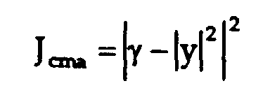
- QPSK modulation where the amplitude of the coded signal is constant, and the phase communicates the symbol, the value of ⁇ is unity (from which the term "constant modulus" is derived.
- CMA2 the minimization is referred to as "CMA2", since the cost function considers the difference of the kurtosis value and the square of the absolute value of the soft output.
- CMA1 Other order CMA minimization (including CMA1) are also utilized in conventional blind equalization.
- Update function 6 adjusts the parameters of equalization according to this CMA minimization.
- this update expression effectively corresponds to an LMS error minimization approach.
- each output y k of equalizer function 4 represents a complex value.
- the present invention may be implemented in a blind equalization function, such as may be utilized on the receive side of a cable modem, realized either as relatively simple logic circuitry, or as simple program instructions.
- the blind equalization function includes an adaptive equalizer, the parameters of which are updated by an update function according to the current output of the adaptive equalizer and the corresponding received symbol value.
- the update function evaluates an error approximation based upon determinations of the maximum of the real and imaginary components of the symbol output from the adaptive equalizer, and of the minimum of the real and imaginary components, with such determinations used to derive the subtrahend to be subtracted from the modulus to derive the error estimate.
- FIG 2 illustrates an example of a system topology of a cable television (CATV) network into which the present invention may be implemented.
- headend 12 is a cable company office from which the CATV programming is forwarded to the cable subscribers, illustrated in Figure 2 as users U; as such, headend 12 will receive video programming signals by way of satellite transmission, land line, or the like. Headend 12 forwards these signals to users U by way of a "tree" network that includes trunks T, splitters 16, and taps 18.
- splitters 16 may be located on either side of taps 18, such as within a locality L which may be a building or city block.
- the transmission medium in a network such as that illustrated in Figure 2 is typically coaxial cable; however, in recent years, some cable systems utilize fiber optic links as trunks T, at least in part, giving rise to the so-called Hybrid Fiber Coax (HFC) infrastructure.
- HFC Hybrid Fiber Coax
- the system of Figure 2 is, of course, well-suited for the unidirectional transmission of information from headend 12 to users U.
- CATV networks are now increasingly being used to provide users U with access to the Internet, in which case bidirectional communication is carried out.
- Such bidirectional communication can be readily carried out over the CATV network topology of Figure 2, by the use of cable modems at the locations of users U.
- the coaxial cable or HFC infrastructure is readily able to carry high data rate transmissions, such as useful in Internet access and use, especially compared against conventional telephone networks that utilize twisted-pair conductors as the transmission facility.
- FIG. 3 illustrates an example of the logical topology of a cable modem network, such as may be implemented into the system topology exemplified in Figure 2.
- central office modem 22 which is located at the headend 12 in the system topology of Figure 2, is connected on one side to the Internet, and on another side to cable modems 20 0 through 20 k at user locations (such as users U in the system topology of Figure 2).
- Each cable modem 20 is, of course, connected to a user or client computer system (not shown) at which data is displayed and entered.
- Downstream path DS carries the transmission of Internet and other computer-readable data from central office modem 22 to cable modems 20, as shown in Figure 3.
- Each of cable modems 20 is assigned an individual address, such that it can detect its own downstream data upon downstream path DS for receipt, and filter out the data intended for the others of cable modems 20; as such, downstream data is effectively broadcast over downstream path DS.
- Central office modem 22 is the exclusive transmitter of data to cable modems 20 (i.e., cable modems 20 will not communicate with one another directly, but instead may only communicate with one another via central office modem 22 or the Internet itself), and as such no downstream media access control (MAC) mechanism is required in this logical arrangement.
- MAC media access control
- Each of cable modems 20 communicate with central office modem 22 over a number of upstream channels, indicated collectively as upstream path UP in Figure 3.
- Each upstream channel within path UP may be shared by multiple cable modems 20, and as such central office modem 22 will include functionality to allocate upstream channels, and slots therewith; additionally, because multiple upstream channels are received by central office modem 22 over upstream path UP, a media access control (MAC) mechanism is provided therewithin.
- the MAC operation particularly in allocating upstream communication slots and managing upstream timing, utilized in the network of Figure 3 is described in Perkins and Gatherer, "Two-way broadband CATV-HFC networks: state-of-the-art and future trends", Computer Networks, Vol. 31 (Elsevier Science B.V., 1999), pp. 313-3216, incorporated herein by this reference.
- communications between cable modem 20 at user location U and central office modem 22 at headend 12 are typically initiated by a request from cable modem 20 that is acknowledged by central office modem 22.
- no fixed training sequence is issued by central office modem 22 for purposes of the setting of the appropriate filter parameters within cable modem 20 to compensate for channel effects.
- cable modem 20 is expected to perform "blind equalization" on the datastream forwarded thereto by central office modem 22, so that channel effects are compensated to at least a sufficient extent to permit higher precision equalization, such as may be implemented by way of decision feedback equalization, to then be utilized.
- cable modem 20 Referring now to Figure 4, the construction of cable modem 20 according to the preferred embodiment of the present invention will now be described in detail. It is to be understood that the present invention may be readily implemented into cable modems of any one of many architectures, and that as such, cable modem 20 illustrated in Figure 4 is presented by way of example only.
- cable modem 20 is preferably realized, in large part, by way of a digital signal processor (DSP) integrated circuit.
- DSP digital signal processor
- Examples of high-performance DSP integrated circuits that are particularly well-suited for use in cable modem 20 include the TMS320C6x digital signal processor family available from Texas Instruments Incorporated.
- TMS320C6x digital signal processor family available from Texas Instruments Incorporated.
- several of the functional blocks of cable modem 20 that are illustrated in Figure 4 will thus not correspond to separate hardware circuits, but will instead correspond to functions or routines performed by the DSP integrated circuit, under the control of program instructions.
- the digital functions described herein will typically be performed by the DSP, with special function integrated circuits typically used to perform the analog and mixed-signal functions, such as those involved in the modulation and demodulation of the signals, signal conversion between the analog and digital domains, and the like.
- the following description of cable modem 20 will be in terms of the functional blocks of Figure 4.
- RF interface 23 effectively operates as a splitter, and is thus in communication with both the transmit and receive sides of cable modem 20.
- RF interface 23 includes an analog-to-digital conversion (ADC) function, by way of which the incoming analog signals are sampled and digitized for processing by the receive side of cable modem 20.
- ADC analog-to-digital conversion
- timing recovery function 24 recovers a clock signal from the incoming signals, relative to a high-precision external crystal oscillator clock in the conventional manner.
- Demodulation function 26 operates to demodulate the received signal, which is contemplated to be in some type of phase-amplitude modulation (PAM) form, thus providing a sequence of digital words to equalization function 28.
- PAM phase-amplitude modulation
- equalization function 28 filters this symbol sequence to compensate for signal distortion introduced by the communications channel.
- equalization function 28 according to the preferred embodiments of the invention, will be described in further detail herein below.
- the digital filter applied by equalization function 28 is set by way of blind equalization during the initialization of the communications session.
- function 30 de-frames the filtered symbols de-framed into a bitstream, for application to decoding function 24.
- Decoding and de-interleaving function 32 reverses such encoding and interleaving that was used in the transmission of the signal.
- function 32 may include Viterbi decoding, Reed-Solomon decoding operation, and inverse convolutional interleaving.
- the decoded output from function 32 is forwarded to media access control MAC and interface function 31, which performs the appropriate MAC functions upon the received signal and interfaces with the host computer of cable modem 20.
- MAC and interface function 31 presents to encoder 34 the digital data that is to be transmitted by cable modem 20 over the CATV network, Encoder 34 encodes the data words into the desired phase and amplitude modulated constellations, according to the particular protocol; for example, a punctured convolutional code may be applied to the data words, to provide good noise immunity.
- the encoded constellation points are then preferably subjected to convolutional interleaving according to the conventional technique, to disperse the effects of any burst error events over the communicated datastream.
- Encoding function 34 may also synchronize the bitstream at a frequency that is derived from the downstream bitstream from headend 12, so that the upstream communication is synchronized with a master clock at central office modem 22.
- Symbol to bit translation function 36 sequences the encoded data into the appropriate data words to be modulated by QAM modulator function 38, which converts the coded constellation points generated by encoder 34 into in-phase and quadrature (i.e., complex) values, which are converted into analog signals of the appropriate amplitude and phase signals by RF interface 23, which includes the appropriate analog-to-digital conversion (ADC) function therein.
- ADC analog-to-digital conversion
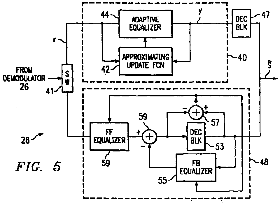
- equalization function 28 includes the parallel arrangement of blind equalizer 40 and decision feedback equalizer (DFE) 48; in this construction, blind equalizer 40 operates initially to effectively compensate for the transmission channel to the extent necessary that DFE 48 is able to then precisely compensate for the channel effects. It is contemplated that blind equalizer 40 and DFE 48 may be implemented in various ways according to the preferred embodiments of the invention, including by way of a sequence of program instructions performable by a digital signal processor (DSP), and by custom logic circuitry.
- DSP digital signal processor
- equalization function 28 is realized through custom logic, some functions such as the feed-forward equalizer path may be shared by blind equalizer 40 and DFE 48, with a controlled switching arrangement included to switch various DFE functions into the blind equalization operation. It is contemplated that those skilled in the art having reference to this specification will be readily able to realize equalization function 28 according to the preferred embodiments of the invention in these, and other, ways, without departing from the scope of the invention as hereinafter claimed.
- signal r k serves as the input to equalization function 28, from demodulator 26 as shown in Figure 4, and is in the form of a stream of digital symbols corresponding to the transmitted signal s(t), as distorted by the response of the transmission channel, and as sampled and converted from analog into digital by interface function 23 of cable modem 20.
- Received signal r k is controlled by switch 41 to be forwarded either to blind equalizer 40 or DFE 48, depending upon the stage of the communications session, as described above.
- Adaptive equalizer 44 in blind equalizer 40 receives signal r k from switch 41 during the initial portion of the communications session.
- Adaptive equalizer 44 is preferably realized by a finite impulse response (FIR) digital filter, for example by way of a tapped delay line with tap weights corresponding to equalization coefficients of the filter.
- the equalization coefficients are updated, in blind equalizer 48, by approximating update function 42 in a manner according to the preferred embodiments of the invention which will described in detail below.
- Signal y k at the output of adaptive equalizer 44 is applied to approximating update function 42.
- Decision block 47 also receives output signal y k and, according to a conventional slicing algorithm, determines detected symbols s ⁇ k to the remainder of cable modem 20.
- DFE 48 is constructed and operates in similar manner as DFE function 8 described above relative to the conventional modem of Figure 1.
- DFE 48 includes feed-forward equalizer 59 which is a compensating FIR filter that is applied to the received signal r k when selected by switch 41, in combination with feedback equalizer 55 which is also preferably realized as an FIR filter.
- the output of feedback equalizer 55 is subtracted from the output of feed-forward equalizer 49 by adder 51, with the resulting difference applied to decision block 53, which applies the appropriate slicing algorithm to generate detected symbols s ⁇ k .
- the equalizer coefficients of feedback equalizer 55 and feed-forward equalizer 59 are updated according to the comparison, performed by adder 57, of the input to and output from decision block 53.
- blind equalizer 40 operates during the initial portion of the transmission, with the filter parameters (or “taps", in the digital filter sense) of adaptive equalizer 44 converging upon an approximate compensation for the distortion effects (i.e., response h(t)) of the transmission channel.
- This convergence occurs due to the operation of approximating update function 42, according to the preferred embodiments of the invention, which determines the equalizer coefficients by way of the Constant Modulus Algorithm, but using approximations to the update equation.
- the resulting parameters in the form of FIR tap weights, are then forwarded to DFE 48, to set the initial operating characteristics of the feed-forward equalizer 59 therein.
- This error approximation uses a known approximation for the magnitude of a complex number y R + iy I (i.e., for the square root of the sum of two squares), for example as described in U.S. Patent No. 3,829,671 and in U.S. Patent No.
- the error approximation according to this first preferred embodiment of the present invention provides a high level of efficiency in its evaluation, thus greatly facilitating the blind equalization process, an example of which will now be described relative to Figure 6, in combination with Figure 5.
- the blind equalization process begins with process 60, in which blind equalizer 40 receives an incoming symbol r k .
- Symbol r k is applied to adaptive equalizer 44 which, in process 62, applies an FIR filter to symbol r k according to the current state of its equalizer coefficients f.
- adaptive equalizer 44 is preferably implemented by way of a multiple-tap delay line, with the equalizer coefficients f included as the tap weights from each tap prior to the output summation; these equalizer coefficients f have values set in the prior passes through the blind equalization process.
- Output symbol y k from adaptive equalizer 44 is forwarded to decision block 47, which performs process 64 to generate the current output symbol s ⁇ k to the remainder of cable modem 20, using a conventional slicing algorithm.
- Output symbol y k from adaptive equalizer 44 is also forwarded to approximating update function 42, as illustrated in Figure 5.
- Error estimation process 66 according to the first preferred embodiment of the present invention is illustrated in Figure 7a relative to a process flow diagram.
- process 66 by way of a sequence of program instructions, executable by a microprocessor, DSP, or other programmable logic device.
- DSP digital signal processor
- process 66 by way of custom logic, through the use of conventional shifters, adders, registers, and the like.
- no detailed description of the construction of such custom logic will be provided herein, it being understood that such construction is well within the skill of the artisan.
- Error estimation process 66 begins, in process 70, with approximating update function 42 receiving real and imaginary components y R , y I of output signal y k from adaptive equalizer 44, in the form of digital data words.
- process 71 the absolute values of real and imaginary components y R , y I are compared with one another. In the event that the absolute value of imaginary component y I is greater than or equal to the absolute value of real component y R (decision 71 is YES), process 72a is performed to set operand MIN to the absolute value of real component y R and to set operand MAX to the absolute value of imaginary component y I .
- process 72b is performed to set operand MIN to the absolute value of imaginary component y I and to set operand MAX to the absolute value of real component y R .
- operand MIN is divided by two which, considering the digital nature of blind equalizer 40, is preferably performed by way of a one-bit shift of operand MIN to the right, as may be readily executed (either in software or hardware) by approximating update function 42.
- process 76 the current value of operand MAX and operand MIN (after the shifting of process 74) are added; in process 78, approximating update function 42 subtracts this sum from the modulus value ⁇ .
- Modulus value ⁇ is preferably set to a constant, as it depends solely upon the type of modulation used in the transmission.
- e ⁇ - (max(
- the error estimation may be generated very efficiently, according to this first preferred embodiment of the present invention.
- the error may be determined by three additions (one each for processes 71, 76, 78), one shift (process 72a or 72b), and the corresponding load and store operations for the intermediate results.
- These extremely low processing demands are much more efficient than those required to perform the square root of the sum of the squares of the component values y I , y R , as necessary according to conventional approaches that utilize the exact form of the error evaluation.
- approximating update function 42 next performs process 68 to determine the next equalization coefficient f k+1 , using error term e, complex received symbol r k , and the current complex output symbol y k , according to the conventional CMA update expression.
- the corresponding update expressions for other CMA orders (e.g., CMA1) are well-known.
- blind equalizer 40 is prepared for the receipt and processing of the next received symbol r k+1 (following the appropriate delay 65), using the updated FIR filter.
- blind equalizer 40 continues over a number of received symbols, until either some convergence criteria is met or until a preselected duration of the communications session has elapsed. At this point, cable modem 10 can assume that adequate compensation for channel effects has been derived by blind equalizer 40, such that DFE 48 may now take over the compensation process, further improving the accuracy of the transmission (and, perhaps, its data rate). Referring back to Figure 5, switch 41 may then forward received symbols to DFE 48 from demodulator 26, following which the communication session continues.
- Figure 8a is a scatter plot illustrating the constellation of a simulated QAM modulated signal, as to be transmitted over a simulated cable modem transmission channel. As evident from Figure 8a, some amount of noise is included in this signal, but the individual QAM points in the constellation are identifiable, such that the modulated symbol values can be retrieved therefrom.
- Figure 8b is a scatter plot illustrating the constellation of Figure 8a after its simulated transmission. As evident from Figure 8b, the simulated transmission channel distorts the modulated signal to a significant extent, such that the particular constellation points cannot be readily distinguished from one another without compensation for the channel effects. Those skilled in the art will recognize that conventional decision feedback equalization would not be successful if applied to a modulated signal having the characteristics of Figure 8b.
- Figure 8c illustrates the result of the application of blind equalization according to the first preferred embodiment of the invention to the simulated modulated signal represented by Figure 8b.
- the blind equalization process according to this first preferred embodiment of the invention compensates for the channel effects to such an extent that the individual symbol points may be distinguished from one another. While some amount of noise, and phase distortion (evident by the tilt in the parallelogram of the constellation) remains present in the constellation of Figure 8c, those skilled in the art will recognize that the application of conventional decision feedback equalization and phase compensation to the constellation of Figure 8c will render useable data.
- the performance illustrated in Figure 8c for the blind equalization process according to this first preferred embodiment of the invention compares favorably to conventional blind equalization in which the exact error term is used.
- the significant efficiencies provided by the blind equalization according to the first preferred embodiment of the invention may be attained, while still providing equalization coefficients that successfully converge to a useable state.
- Process 66' is performed at the same stage in the overall blind equalization process as process 66 (see Figure 6).
- process 66' it is contemplated that those skilled in the art having reference to this specification will also be readily able to implement process 66' by way of a sequence of program instructions, executable by a microprocessor, DSP, or other programmable logic device, as well as by way of custom logic, through the use of conventional shifters, adders, registers, and the like.
- Process 80 initiates error estimation process 66' with the receipt or retrieval, by approximating update function 42, of digital words corresponding to the real and imaginary components y R , y I of output signal y k from adaptive equalizer 44.
- process 81 the absolute values of real and imaginary components y R , y I are compared with one another.
- process 82a sets operand MIN to the absolute value of real component y R and operand MAX to the absolute value of imaginary component y I ; if the absolute value of real component y R is greater than the absolute value of imaginary component y I (decision 81 is NO), process 82b sets operand MIN to the absolute value of imaginary component y I and operand MAX to the absolute value of real component y R .
- process 84 may be readily performed by way of a two-bit shift of operand MAX.
- the shifted operand is then stored by approximating update function 42 in a register or other store as operand SMAX, considering that operand MAX (in its unshifted value) is also needed later.
- Operand Z is then evaluated in process 86 for the current symbol, by subtracting the value of operand SMAX from the value of operand MIN.
- decision 87 operand Z is compared against zero. As is known in the art, if this blind equalization process is realized as instruction code in a programmable device, the comparison of decision 87 may be executing simply by testing a "negative" flag in a control register.
- control passes to process 88 for determination of the error term.
- approximating update function 42 evaluates the error term as simply the difference between modulus ⁇ and the value of operand MAX (for CMA1); following this evaluation process 88, control is then passed to process 68 for completion of the update process for the current symbol.
- the estimated subtrahend will be raised to the appropriate power prior to the subtraction of process 88..
- operand Z is divided by two, by way of a right shift by one bit position.
- Process 92 is then executed to add the shifted value of operand Z to the value of operand MAX; this sum (raised to the appropriate power, if necessary) is then subtracted from the value of modulus ⁇ in process 94 to derive the error term.
- Control then passes to process 68 for completion of the coefficient update process ( Figure 6).
- the present invention therefore, significant efficiency in the blind equalization process is provided by the preferred embodiments of the present invention, without degrading the convergence of equalization coefficients upon proper compensation. It is therefore contemplated that the present invention will be beneficial in many applications, including data communications using cable modems and other modulation approaches, as well as other applications in which blind equalization may be performed.
Landscapes
- Engineering & Computer Science (AREA)
- Physics & Mathematics (AREA)
- General Physics & Mathematics (AREA)
- Computational Mathematics (AREA)
- Mathematical Analysis (AREA)
- Pure & Applied Mathematics (AREA)
- Theoretical Computer Science (AREA)
- General Engineering & Computer Science (AREA)
- Mathematical Optimization (AREA)
- Computing Systems (AREA)
- Power Engineering (AREA)
- Computer Networks & Wireless Communication (AREA)
- Signal Processing (AREA)
- Cable Transmission Systems, Equalization Of Radio And Reduction Of Echo (AREA)
- Dc Digital Transmission (AREA)
- Digital Transmission Methods That Use Modulated Carrier Waves (AREA)
Abstract
Description


Claims (14)
- A method of setting equalization coefficients for data signals received over a communications channel, comprising the steps of:receiving a data symbol from the communications channel;applying an equalizer filter to the received data symbol to produce an output symbol having real and imaginary components;generating an error estimate for the output symbol by performing the steps of:determining the minimum and maximum of the absolute value of the real and imaginary components of the output symbol;generating a subtrahend using the determined minimum and maximum; andsubtracting the subtrahend from a modulus value to generate an error estimate;updating an equalization coefficient for the equalizer filter from a combination of the received data symbol, the error estimate, and the output symbol; andrepeating the receiving, applying, and updating steps for a plurality of received data symbols.
- The method of claim 1, wherein the step of generating a subtrahend comprises:dividing the determined minimum by two; andadding the determined maximum and divided determined minimum.
- The method of claim 2, wherein the step of generating a subtrahend further comprises:raising the sum of the determined maximum and divided determined minimum to a selected power to produce the subtrahend.
- The method of claim 3, wherein the dividing step comprises shifting a data word representing the determined minimum.
- The method of claim 1, wherein the step of generating a subtrahend comprises:dividing the determined maximum by four;generating a difference operand corresponding to the determined minimum minus the divided determined maximum;responsive to the difference operand being less than zero, generating a subtrahend corresponding to the determined maximum; andresponsive to the difference operand being greater than or equal to zero, performing the operations of:dividing the difference operand by two;generating a subtrahend corresponding to a sum of the divided difference operand and the determined maximum.
- The method of claim 5, wherein the step of generating a subtrahend corresponding to the determined maximum further comprises:raising the determined maximum to a selected power;
and wherein the step of generating a subtrahend corresponding to a sum of the divided difference operand and the determined maximum further comprises:raising the sum of the divided difference operand and the determined maximum to a selected power. - The method of claim 6, wherein the dividing step comprises shifting a data word by a selected number of bit positions.
- The method of claim 1, wherein the repeating step is performed for a selected plurality of received data symbols;and further comprising:then forwarding the equalization coefficients to a decision feedback equalizer; andoperating the decision feedback equalizer to produce detected data symbol values.
- A communications device for receiving data communications, comprising:an interface (23) for receiving modulated signals from a communications channel;a demodulator (26) for demodulating the received modulated signals into digital data symbols;an equalizer (28) for compensating the received modulated signals for distortion of the communications channel, comprising:a blind equalizer (40), comprising:an adaptive equalizer (44) for applying a digital filter to the data symbols, having an input coupled to the demodulator, and having an output;an approximating update function (42), having an input coupled to the output of the adaptive equalizer (44) for receiving output symbols having real and imaginary components therefrom, having an input coupled to the demodulator (26) to receive data symbols therefrom, and having an output coupled to the adaptive equalizer (44), the approximating update function (42) for updating an equalization coefficient of the adaptive equalizer (44), by performing the operations of:generating an error estimate for the output symbol by performing the steps of:determining the minimum and maximum of the absolute value of the real and imaginary components of the output symbol;generating a subtrahend using the determined minimum and maximum; andsubtracting the subtrahend from a modulus value to generate an error estimate;generating an updated equalization coefficient from a combination of the received data symbol, the error estimate, and the output symbol; andrepeating the receiving, applying, and updating steps for a plurality of received data symbols; anda decision block (47) having an input coupled to the output of the adaptive equalizer (44), for generating a detected symbol from the output symbol.
- The communications device of claim 9, further comprising:a decision feedback equalizer (48), having an input coupled to the demodulator (26).
- The communications device of claim 10, wherein the decision feedback equalizer (48) comprises a feed-forward equalizer (59), for applying a digital filter to data symbols received from the demodulator (26) according to a plurality of equalizer coefficients;
wherein the plurality of equalizer coefficients of the feed-forward equalizer (59) are initialized by the plurality of equalizer coefficients of the adaptive equalizer (44) of the blind equalizer (40). - The communications device of claim 10, wherein the approximating update function generates the subtrahend by:dividing the determined minimum by two; andadding the determined maximum and divided determined minimum; andraising the sum of the determined maximum and divided determined minimum to a selected power to produce the subtrahend.
- The communications device of claim 12, wherein the approximating update function generates the subtrahend by:dividing the determined maximum by four;generating a difference operand corresponding to the determined minimum minus the divided determined maximum;responsive to the difference operand being less than zero, generating a subtrahend corresponding to the determined maximum; andresponsive to the difference operand being greater than or equal to zero, performing the operations of:dividing the difference operand by two;generating a subtrahend corresponding to a sum of the divided difference operand and the determined maximum.
- The communications device of claim 9, wherein the interface is for receiving modulated signals from a cable television network.
Applications Claiming Priority (2)
| Application Number | Priority Date | Filing Date | Title |
|---|---|---|---|
| US431687 | 1999-11-01 | ||
| US09/431,687 US6370191B1 (en) | 1999-11-01 | 1999-11-01 | Efficient implementation of error approximation in blind equalization of data communications |
Publications (2)
| Publication Number | Publication Date |
|---|---|
| EP1096746A2 true EP1096746A2 (en) | 2001-05-02 |
| EP1096746A3 EP1096746A3 (en) | 2006-01-18 |
Family
ID=23713014
Family Applications (1)
| Application Number | Title | Priority Date | Filing Date |
|---|---|---|---|
| EP00123420A Withdrawn EP1096746A3 (en) | 1999-11-01 | 2000-11-02 | Error estimation function to update a blind equalizer |
Country Status (3)
| Country | Link |
|---|---|
| US (1) | US6370191B1 (en) |
| EP (1) | EP1096746A3 (en) |
| JP (1) | JP2001189686A (en) |
Cited By (2)
| Publication number | Priority date | Publication date | Assignee | Title |
|---|---|---|---|---|
| EP1748611A1 (en) | 2005-07-28 | 2007-01-31 | Altera Corporation | High-speed data equalization circuitry and method |
| CN108449292A (en) * | 2018-02-28 | 2018-08-24 | 深圳市太赫兹科技创新研究院 | Blind balance method, system, computer equipment and readable storage medium storing program for executing |
Families Citing this family (28)
| Publication number | Priority date | Publication date | Assignee | Title |
|---|---|---|---|---|
| JP2001060896A (en) * | 1999-08-23 | 2001-03-06 | Nec Corp | Automatic equalizer |
| JP2001256728A (en) * | 2000-03-10 | 2001-09-21 | Fujitsu Ltd | Semiconductor device |
| US7039939B1 (en) * | 2000-05-09 | 2006-05-02 | Cisco Technology, Inc. | Method and apparatus for creating virtual upstream channels for enhanced lookahead channel parameter testing |
| US6975685B1 (en) * | 2000-10-24 | 2005-12-13 | Agere Systems Inc. | Apparatus and method for multi-channel communications system |
| US7027500B1 (en) * | 2000-12-12 | 2006-04-11 | Ati Research, Inc. | Linear prediction based initialization of a single-axis blind equalizer for VSB signals |
| US8291457B2 (en) | 2001-05-24 | 2012-10-16 | Vixs Systems, Inc. | Channel selection in a multimedia system |
| US20090031419A1 (en) | 2001-05-24 | 2009-01-29 | Indra Laksono | Multimedia system and server and methods for use therewith |
| US7269216B2 (en) * | 2001-06-05 | 2007-09-11 | Kennedy Rodney A | Blind magnitude equalizer for segment sync-based timing recovery of receivers |
| US7027499B2 (en) * | 2001-06-20 | 2006-04-11 | Agere Systems Inc. | Detection and correction circuit for blind equalization convergence errors |
| US7221389B2 (en) | 2002-02-15 | 2007-05-22 | Avocent Corporation | Automatic equalization of video signals |
| US7450636B2 (en) * | 2002-09-05 | 2008-11-11 | Avago Technologies General Ip (Singapore) Pte. Ltd. | Adaptive transmit equalizer |
| US7321623B2 (en) * | 2002-10-01 | 2008-01-22 | Avocent Corporation | Video compression system |
| US20050027771A1 (en) * | 2003-07-30 | 2005-02-03 | Broadcom Corporation | System and method for approximating division |
| US7489362B2 (en) * | 2003-03-04 | 2009-02-10 | Broadcom Corporation | Television functionality on a chip |
| US9560371B2 (en) * | 2003-07-30 | 2017-01-31 | Avocent Corporation | Video compression system |
| US7457461B2 (en) * | 2004-06-25 | 2008-11-25 | Avocent Corporation | Video compression noise immunity |
| US7809096B2 (en) * | 2005-03-01 | 2010-10-05 | Broadcom Corporation | Adaptive interference cancellation algorithm using speech mode dependent thresholds |
| US7894514B2 (en) * | 2005-09-29 | 2011-02-22 | Alcatel-Lucent Usa Inc. | Receiver techniques for wireless communication |
| US7782961B2 (en) * | 2006-04-28 | 2010-08-24 | Avocent Corporation | DVC delta commands |
| US20090067483A1 (en) * | 2007-08-29 | 2009-03-12 | Raul Casas | Efficient adaptive equalizer implementation |
| US7929598B2 (en) * | 2007-12-31 | 2011-04-19 | Intel Corporation | Lower processing rate decision feedback equalizer for higher rate carrier signal |
| US7872978B1 (en) * | 2008-04-18 | 2011-01-18 | Link—A—Media Devices Corporation | Obtaining parameters for minimizing an error event probability |
| EP2112770B1 (en) * | 2008-04-24 | 2011-10-26 | Alcatel Lucent | Method and hybrid circuit for attenuating near-end crosstalk in a bidirectional signal transmission |
| US8223830B2 (en) * | 2009-06-18 | 2012-07-17 | Agilent Technologies, Inc. | Method and apparatus for determining equalization coefficients |
| CN101924718B (en) * | 2010-08-30 | 2013-07-03 | 南京信息工程大学 | Hybrid wavelet neural network blind equalization method controlled by fuzzy neutral network |
| US9768984B2 (en) * | 2015-03-06 | 2017-09-19 | Mediatek, Inc. | Electronic device with equalization, integrated circuit and methods therefor |
| TWI640181B (en) * | 2016-03-02 | 2018-11-01 | 晨星半導體股份有限公司 | Equalizer apparatus and viterbi algorithm based decision method |
| KR20250076610A (en) * | 2022-10-31 | 2025-05-29 | 마이크로칩 터치 솔루션즈 리미티드 | Physician-based noise equalization |
Family Cites Families (8)
| Publication number | Priority date | Publication date | Assignee | Title |
|---|---|---|---|---|
| US3829671A (en) * | 1973-04-25 | 1974-08-13 | Westinghouse Electric Corp | Method and circuit for calculating the square root of the sum of two squares |
| US4553260A (en) * | 1983-03-18 | 1985-11-12 | Honeywell Inc. | Means and method of processing optical image edge data |
| US4599701A (en) * | 1983-10-19 | 1986-07-08 | Grumman Aerospace Corporation | Complex magnitude computation |
| US5603112A (en) * | 1991-04-26 | 1997-02-11 | Motorola, Inc. | Received signal strength indicator utilizing approximation factors and the I and Q signal components |
| US5602507A (en) * | 1993-11-05 | 1997-02-11 | Ntt Mobile Communications Network Inc. | Adaptive demodulating method for generating replica and demodulator thereof |
| KR0144294B1 (en) * | 1994-12-14 | 1998-07-15 | 배순훈 | Equalizer for improving a convergence characteristics |
| JPH09325955A (en) * | 1996-06-05 | 1997-12-16 | Sharp Corp | Square root arithmetic circuit for sum of squares |
| US6081822A (en) * | 1998-03-11 | 2000-06-27 | Agilent Technologies, Inc. | Approximating signal power and noise power in a system |
-
1999
- 1999-11-01 US US09/431,687 patent/US6370191B1/en not_active Expired - Lifetime
-
2000
- 2000-10-31 JP JP2000333364A patent/JP2001189686A/en active Pending
- 2000-11-02 EP EP00123420A patent/EP1096746A3/en not_active Withdrawn
Cited By (5)
| Publication number | Priority date | Publication date | Assignee | Title |
|---|---|---|---|---|
| EP1748611A1 (en) | 2005-07-28 | 2007-01-31 | Altera Corporation | High-speed data equalization circuitry and method |
| CN101110597B (en) * | 2005-07-28 | 2012-12-05 | 阿尔特拉公司 | High-speed data equalization circuitry and method |
| US8743943B2 (en) | 2005-07-28 | 2014-06-03 | Altera Corporation | High-speed data reception circuitry and methods |
| CN108449292A (en) * | 2018-02-28 | 2018-08-24 | 深圳市太赫兹科技创新研究院 | Blind balance method, system, computer equipment and readable storage medium storing program for executing |
| WO2019165657A1 (en) * | 2018-02-28 | 2019-09-06 | 深圳市太赫兹科技创新研究院 | Blind equalization method and system, computer device and readable storage medium |
Also Published As
| Publication number | Publication date |
|---|---|
| US6370191B1 (en) | 2002-04-09 |
| EP1096746A3 (en) | 2006-01-18 |
| JP2001189686A (en) | 2001-07-10 |
Similar Documents
| Publication | Publication Date | Title |
|---|---|---|
| US6370191B1 (en) | Efficient implementation of error approximation in blind equalization of data communications | |
| US7076514B2 (en) | Method and system for computing pre-equalizer coefficients | |
| US7218681B2 (en) | Method and apparatus for cross-talk mitigation through joint multiuser adaptive pre-coding | |
| US6067319A (en) | Method for equalization of a quadrature amplitude modulated signal | |
| US6597746B1 (en) | System and method for peak to average power ratio reduction | |
| USRE42558E1 (en) | Joint adaptive optimization of soft decision device and feedback equalizer | |
| US7023912B2 (en) | Hybrid adaptive equalizer for optical communications systems | |
| US20030231709A1 (en) | Symbol-based decision feedback equalizer (DEF) optimal equalization method and apparatus with maximum likelihood sequence estimation for wireless receivers under multipath channels | |
| EP1049300B1 (en) | PCM modem with pre-equalisation | |
| US5471504A (en) | Bilinear decision feedback equalizer | |
| US7003100B2 (en) | Modem with enhanced echo canceler | |
| US6269116B1 (en) | Method and arrangement for demodulating data symbols | |
| US20030048840A1 (en) | Adaptive equalizer | |
| WO1999023796A1 (en) | Error filtering in a decision feedback equalizer | |
| CN101106386A (en) | Time domain self-adapted balancer | |
| US6687288B1 (en) | NEXT cancellation for modem pools | |
| US6463106B1 (en) | Receiver with adaptive processing | |
| Kurakake et al. | A blind 1024-QAM demodulator for cable television | |
| JPH11340877A (en) | Adaptive DC compensation | |
| Shin et al. | A 64/256 QAM receiver chip for high-speed communications | |
| US20030112903A1 (en) | Combined feedforward filter for a decision feedback equalizer | |
| Lee et al. | A high-speed blind DFE equalizer using an error feedback filter for QAM modems | |
| Chen et al. | Efficient decision feedback blind equalizer with multi-level modulus algorithm and two-stage feedback scheme for high-order QAM cable receivers | |
| CN111107025B (en) | Adaptive Equalizer in GFSK Receiver | |
| Chung et al. | Timing phase offset recovery based on dispersion minimization |
Legal Events
| Date | Code | Title | Description |
|---|---|---|---|
| PUAI | Public reference made under article 153(3) epc to a published international application that has entered the european phase |
Free format text: ORIGINAL CODE: 0009012 |
|
| AK | Designated contracting states |
Kind code of ref document: A2 Designated state(s): AT BE CH CY DE DK ES FI FR GB GR IE IT LI LU MC NL PT SE TR |
|
| AX | Request for extension of the european patent |
Free format text: AL;LT;LV;MK;RO;SI |
|
| PUAL | Search report despatched |
Free format text: ORIGINAL CODE: 0009013 |
|
| AK | Designated contracting states |
Kind code of ref document: A3 Designated state(s): AT BE CH CY DE DK ES FI FR GB GR IE IT LI LU MC NL PT SE TR |
|
| AX | Request for extension of the european patent |
Extension state: AL LT LV MK RO SI |
|
| AKX | Designation fees paid | ||
| STAA | Information on the status of an ep patent application or granted ep patent |
Free format text: STATUS: THE APPLICATION IS DEEMED TO BE WITHDRAWN |
|
| 18D | Application deemed to be withdrawn |
Effective date: 20060719 |
|
| REG | Reference to a national code |
Ref country code: DE Ref legal event code: 8566 |