EP1096697A2 - Radio communication system and method for controlling a gain of a receiver portion of the system - Google Patents
Radio communication system and method for controlling a gain of a receiver portion of the system Download PDFInfo
- Publication number
- EP1096697A2 EP1096697A2 EP00122203A EP00122203A EP1096697A2 EP 1096697 A2 EP1096697 A2 EP 1096697A2 EP 00122203 A EP00122203 A EP 00122203A EP 00122203 A EP00122203 A EP 00122203A EP 1096697 A2 EP1096697 A2 EP 1096697A2
- Authority
- EP
- European Patent Office
- Prior art keywords
- band
- received signal
- selector switch
- pass filters
- input
- Prior art date
- Legal status (The legal status is an assumption and is not a legal conclusion. Google has not performed a legal analysis and makes no representation as to the accuracy of the status listed.)
- Granted
Links
Images








Classifications
-
- H—ELECTRICITY
- H04—ELECTRIC COMMUNICATION TECHNIQUE
- H04B—TRANSMISSION
- H04B7/00—Radio transmission systems, i.e. using radiation field
- H04B7/02—Diversity systems; Multi-antenna system, i.e. transmission or reception using multiple antennas
- H04B7/04—Diversity systems; Multi-antenna system, i.e. transmission or reception using multiple antennas using two or more spaced independent antennas
- H04B7/08—Diversity systems; Multi-antenna system, i.e. transmission or reception using multiple antennas using two or more spaced independent antennas at the receiving station
- H04B7/0802—Diversity systems; Multi-antenna system, i.e. transmission or reception using multiple antennas using two or more spaced independent antennas at the receiving station using antenna selection
Definitions
- the present invention generally relates to a radio communication system that is used as a mobile station in a mobile communication system. More particularly, the present invention relates to a radio communication system and a method for controlling a gain of a receiver portion of the radio communication system with a simple configuration.
- portable telephones With rapid development of mobile communication systems using portable telephones or other radio communication systems (hereinafter, called portable telephones), several attempts have been made to upgrade the communication environment so as to meet the demands of the increase of communication channels between the base station and the mobile stations and the noiseless receiving quality of the mobile stations. For example, the attempts are performed to increase the number of base stations used to relay the communication from the mobile stations, the attempts are performed to optimize the locations where the base stations are installed.
- a portable telephone may possibly be situated at a location that is too near the base station or too far from the base station.
- a transmission power control is carried out in accordance with the distance between the portable telephone and the base station, as follows. That is, a received signal strength of the signal, transmitted by the base station, is measured at the portable telephone, and a measured power of the received signal is notified to the base station by the portable telephone. When this notification is received at the base station, the base station controls the transmission power of the channel for the portable telephone based on the measured power of the received signal sent by the portable telephone, so as to achieve the optimum transmission power for the portable telephone.
- a received signal strength of the signal, transmitted to the base station by a corresponding portable telephone, is measured at the base station, and an optimum transmission power for the portable telephone is determined by the based station based on the measured power of the received signal.
- the base station transmits a control signal to the portable telephone, so that the optimum transmission power of the channel is set at the portable telephone based on the control signal sent by the base station.
- the receiver portion of a portable telephone is designed to achieve an increased level of sensibility to a received signal.
- the level of sensibility is increased by simply increasing the gain of the receiver portion, a distortion of the received signal waveform occurs due to the non-linearity that appears as the received signal strength increases. In such a case, the dynamic range in practical use becomes significantly narrow.
- the gain of the receiver portion of the portable telephone, or the level of amplification of the received signal at the receiver portion is properly varied.
- the gain of the receiver portion is controlled by taking one of the following methods.
- the variable attenuator must component.
- the total number of components needed for the entire portable telephone is increased, and it is difficult that the above method (1) provide a small-size, lightweight configuration of the radio communication system that needs a wide dynamic range.
- the above method (2) is taken, the configuration requiring the special low-noise amplifier at the radio-frequency section is complicated. Further, an additional control circuit is also needed to control the gain of the low-noise amplifier at the radio-frequency section. It is difficult that the above method (2) provide a small-size, lightweight configuration of the radio communication system that needs a wide dynamic range.
- preferred embodiments of the present invention provide an improved radio communication system that achieves a wide dynamic range of the receiver portion without causing a distortion of the received signal waveform, by using a simple, small-size configuration.
- the preferred embodiments of the present invention provide an improved radio receiver apparatus that achieves a wide dynamic range without causing a distortion of the received signal waveform, by using a simple, small-size configuration.
- the preferred embodiments of the present invention provide an improved method of controlling a gain of a receiver portion of a radio communication system that achieves a wide dynamic range of the receiver portion without causing a distortion of the received signal waveform, by using a simple, small-size configuration.
- a radio receiver apparatus comprises: a plurality of band-pass filters each allowing signals lying within a particular one of a plurality of distinct frequency bands to pass through the filter; a selector switch having an input and a plurality of outputs connected to the plurality of band-pass filters, the selector switch delivering a received signal at the input to one of the plurality of band-pass filters via a selected one of the plurality of outputs connected to the one of the plurality of band-pass filters; and a control unit controlling switching of the selector switch in accordance with both a specified frequency contained in the received signal and a receiving level of the received signal, so that the input of the selector switch is connected to the selected one of the plurality of outputs so as to pass the received signal through the one of the plurality of band-pass filters.
- a radio receiver apparatus comprises: a plurality of band-pass filters each of which allows signals lying within a particular one of a plurality of distinct frequency bands to pass through the filter, the plurality of band-pass filters having insertion loss characteristics that are distinct from each other with respect to an input signal frequency; a selector switch which has an input and a plurality of outputs connected to the plurality of band-pass filters, the selector switch delivering a received signal at the input to one of the plurality of band-pass filters via a selected one of the plurality of outputs connected to the one of the plurality of band-pass filters; and a control unit which controls switching of the selector switch in accordance with both a specified frequency contained in the received signal and a receiving level of the received signal, so that the input of the selector switch is connected to the selected one of the plurality of outputs so as to select one of the plurality of band-pass filters that has the insertion loss characteristics suited to the receiving level of the received signal.
- a radio receiver apparatus comprises: a plurality of band-pass filters each of which allows signals lying within a particular one of a plurality of distinct frequency bands to pass through the filter; a selector switch which has an input and a plurality of outputs connected to the plurality of band-pass filters, the selector switch delivering a received signal at the input to one of the plurality of band-pass filters via a selected one of the plurality of outputs connected to the one of the plurality of band-pass filters; and a control unit which controls switching of the selector switch in accordance with a measured power of the received signal at an input of the control unit, so that the input of the selector switch is connected to the selected one of the plurality of outputs so as to pass the received signal through the one of the plurality of band-pass filters, wherein the control unit changes the selected one of the plurality of outputs of the selector switch to another output through the switching of the selector switch when the measured power of the received signal is above a predetermined value, and where
- a radio communication system receives a signal having a specified frequency from a base station, measures a power of the received signal, and transmits a notification indicative of the measured power of the received signal, to the base station, the radio communication system comprising: a plurality of band-pass filters each of which allows signals lying within a particular one of a plurality of distinct frequency bands to pass through the filter; a selector switch which has an input and a plurality of outputs connected to the plurality of band-pass filters, the selector switch delivering a received signal at the input to one of the plurality of band-pass filters via a selected one of the plurality of outputs connected to the one of the plurality of band-pass filters; and a control unit which controls switching of the selector switch in accordance with a measured power of the received signal at an input of the control unit, so that the input of the selector switch is connected to the selected one of the plurality of outputs so as to pass the received signal through the one of the plurality of band-pass filters
- a method of controlling a gain of a radio receiver apparatus comprises the steps of: providing a plurality of band-pass filters each allowing signals lying within a particular one of a plurality of distinct frequency bands to pass through the filter; providing a selector switch having an input and a plurality of outputs connected to the plurality of band-pass filters, the selector switch delivering a received signal at the input to one of the plurality of band-pass filters via a selected one of the plurality of outputs connected to the one of the plurality of band-pass filters; measuring a power of the received signal; and controlling switching of the selector switch in accordance with the measured power of the received signal, so that the input of the selector switch is connected to the selected one of the plurality of outputs so as to pass the received signal through the one of the plurality of band-pass filters.
- a method of controlling a gain of a receiver portion of a radio communication system comprises the steps of: providing a plurality of band-pass filters each allowing signals lying within a particular one of a plurality of distinct frequency bands to pass through the filter, the plurality of band-pass filters having insertion loss characteristics that are distinct from each other with respect to an input signal frequency; providing a selector switch having an input and a plurality of outputs connected to the plurality of band-pass filters, the selector switch delivering a received signal at the input to one of the plurality of band-pass filters via a selected one of the plurality of outputs connected to the one of the plurality of band-pass filters; detecting the specified frequency contained in the received signal and a receiving level of the received signal at an output of said one of the plurality of band-pass filters; and controlling switching of the selector switch in accordance with both the specified frequency contained in the received signal and the receiving level of the received signal, so that the input
- the switching of the selector switch is properly controlled in accordance with the receiving level of the received signal so as to deliver the received signal to the selected one of the plurality of band-pass filters.
- the radio receiver apparatus and the radio communication system of the above preferred embodiments are effective in achieving a wide dynamic range without causing a distortion of the received signal waveform, by using a simple, small-size configuration.
- the switching of the selector switch is suitably controlled in accordance with the receiving level of the received signal so as to deliver the received signal to the selected one of the plurality of band-pass filters.
- the gain controlling method of the above preferred embodiments is effective in achieving a wide dynamic range without causing a distortion of the received signal waveform, by using a simple, small-size configuration.
- FIG. 1 shows a mobile communication system to which one embodiment of the present invention is applied.
- the mobile communication system shown in FIG. 1, is, for example, a personal digital cellular (PDC) mobile telephone system.
- PDC personal digital cellular
- a plurality of portable telephones 10 are provided as mobile stations, a plurality of base stations 20 are installed at high-rise buildings or the like, and a base-station control equipment 30 is provided to carry out the channel control.
- a mobile exchange (not shown) is connected to the base-station control equipment 30.
- the portable telephones 10 are connected through the mobile exchange to a public switched telephone network.
- the portable telephones 10 and the base stations 20 are connected to each other by radio communication paths.
- the base stations 20 and the base-station control equipment 30 are connected to each other by wired or wireless communication paths.
- One embodiment of the radio communication system of the invention is applied to each of the portable telephones 10 in the mobile communication system of FIG. 1.
- the portable telephones 10 are of a dual-band compatible type that is configured to receive a signal lying within a selected one of two frequency bands.
- a detailed configuration of each portable telephone 10 will be described below.
- the base station 20 measures a received signal strength of a signal that is transmitted to the base station 20 by the portable telephone 10, and determines an optimum transmission power for the portable telephone 10 based on the result of the measurement. Then, the base station 20 transmits a control signal to the portable telephone 10, so that the optimum transmission power of the channel is set at the portable telephone 10 based on the control signal sent by the base station 20. Further, the base station 20 receives a notification, sent by the portable telephone 20, which is based on a result of measurement of a received signal strength of a signal that is transmitted from the base station 20 to the portable telephone 10. Then, the base station 20 controls the transmission power of the channel for the portable telephone 10 based on the measured received signal strength sent by the portable telephone 10, such that the optimum transmission power is attained.
- the portable telephone 10 to which one embodiment of the radio communication system of the invention is applied is configured to receive a specified-frequency signal lying within a selected one of two frequency bands: 810-830 MHz and 870-885 MHz.
- the specified frequency of the received signal for the portable telephone 10 is notified to the portable telephone 10 by the base station 20 (or by the base-station control equipment 30) when establishing a communication channel between the base station 20 and the portable telephone 10.
- the portable telephone 10 is provided with a receiving-level detection unit which detects a receiving level or state of the received signal designating the portable telephone 10 as the destination station.
- the received signal designating the portable telephone 10 as the destination station is included in a transmission signal transmitted by the base station 20, and contains a destination identification of the portable telephone 10.
- FIG. 2 shows a configuration of a receiver portion of the portable telephone 10 to which one preferred embodiment of the radio communication system of the invention is applied.
- a signal transmitted to the portable telephone 10 by the base station 20 is received at one of an antenna A1 and an antenna A2.
- one of the two antennas A1 and A2 is provided for the purposes of transmission and reception, and the other is provided for the purpose of reception only.
- the received signal is delivered to a low-noise amplifier (LNA) 12 via an antenna duplexer (AD) 50 and a band-pass filter (BPF) 11.
- LNA 12 amplifies the received signal that is a low-level radio-frequency signal, and outputs the amplified signal to a band switching device (BSD) 13.
- BSD band switching device
- the band switching device 13 controls switching of a selector switch to one of a first band-pass filter BPF1 (8 10-830 MHz) or a second band-pass filter BPF2 (870-885 MHz) in accordance with control signals CNT1 and CNT2 sent by a control circuit (CC) 40.
- the radio-frequency signal, output by the BSD 13, is delivered to a first mixer 14.
- the radio-frequency signal sent by the BSD 13 is mixed with a local signal output by a local oscillator LO1, so that the first mixer 14 generates a first intermediate-frequency signal from the radio-frequency signal.
- the first intermediate-frequency signal is passed through a band-pass filter (BPF) 15, and the first intermediate-frequency signal, output by the BPF 15, is delivered to a second mixer 16.
- BPF band-pass filter
- the first intermediate-frequency signal sent by the BPF 15 is mixed with a local signal output by a local oscillator LO2, so that the second mixer 16 generates a second intermediate-frequency signal from the first intermediate-frequency signal.
- the second intermediate-frequency signal is passed through a band-pass filter (BPF) 17, and the second intermediate-frequency signal, output by the BPF 17, is delivered to each of a limiter/amplifier (L/AMP) 18 and a receiving-level detection unit (RXD) 19.
- BPF band-pass filter
- L/AMP limiter/amplifier
- RXD receiving-level detection unit
- the received signal designating the portable telephone 10 as the destination station, is detected from the second intermediate-frequency signal at the receiving-level detection unit 19. Further, the limiter/amplifier 18 outputs an amplified signal that is produced from the second intermediate-frequency signal, to a demodulator section (not shown) of the portable telephone 10. In the demodulator section, the amplified signal output by the limiter/amplifier 18 is subjected to demodulation.
- the above-described receiver portion of the portable telephone employs a known double-heterodyne scheme. Not only the double-heterodyne scheme but also a known direct frequency conversion technique may be applied to the receiver portion of the portable telephone 10.
- the receiving-level detection unit 19 detects a receiving level of the received signal (or a received signal strength indication RSSI) from the second intermediate-frequency signal output by the BPF 17.
- the receiving-level detection unit 19 supplies a receiving-level signal indicative of the receiving level of the received signal (or indicative of the detected RSSI), to the control circuit 40.
- the control circuit 40 receives the specified frequency of the received signal for the portable telephone 10 from the demodulator section (not shown), selects one of the first band-pass filter or the second band-pass filter in the band switching device (BSD) 13 based on the specified frequency, and allows the band switching device (BSD) 13 to control the switching of the selector switch to the selected one of the first or second band-pass filter, in response to the receiving-level signal sent by the receiving-level detection unit 19.
- the above-described receiver portion of the portable telephone 10 of FIG. 2 corresponds to the radio receiver apparatus in the claims.
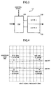
- FIG. 3 shows a configuration of the band switching device 13 in the receiver portion of the portable telephone of FIG. 2.
- the band switching device 13 generally includes a selector switch (SW) 131, a first band-pass filter (BPF1) 132, and a second band-pass filter (BPF2) 133.
- SW selector switch
- BPF1 first band-pass filter
- BPF2 second band-pass filter
- the BSD 13 of the present embodiment uses the two band-pass filters.
- the selector switch 131 is a one-input, two-output radio-frequency switching circuit including a first transmission path and a second transmission path, the first transmission path connecting the input with one of the two outputs, and the second transmission path connecting the input with the other of the two outputs.
- active elements are respectively inserted. These active elements are constituted by, for example, a gallium-arsenide field-effect transistor (GaAs FET) or a pin diode. The active elements are turned ON or OFF in response to the control signals CNT1 and CNT2 sent by the control circuit 40.
- the active element of one of the first and second transmission paths of the switch 131 When the active element of one of the first and second transmission paths of the switch 131 is turned ON, the active element of the other path of the switch 131 is turned OFF, such that an insertion loss of one of the first and second paths is larger than an insertion loss of the other path.
- an insertion loss of the path in which the corresponding active element is turned OFF is called the isolation.
- the selector switch 131 may be constituted by a semiconductor switch of another type or a mechanical switch.
- FIG. 4 shows insertion loss characteristics of the selector switch 131 in the band switching device 13 of FIG. 3.
- the selector switch 131 is a one-input, two-output radio-frequency switching circuit using the active elements made of a GaAs FET, and disconnected from the first and second band-pass filters 132 and 131, and that a 50-ohm terminating circuit is connected to one of the two output terminals of the switch 131 where the corresponding transmission path is in a non-testing condition.
- the insertion loss characteristics of the switch 131 shown in FIG. 4 are obtained as a result of the single-piece testing of the radio-frequency switching circuit.
- the solid-line curve indicates the insertion loss characteristics of the switch 131 when the active element of the path being tested is turned ON
- the dotted-line curve indicates the insertion loss characteristics of the switch 131 when the active element of the path being tested is turned OFF.
- the isolation of the switch 131 (or the insertion loss of the path in which the corresponding active element is turned OFF) is set at about 20 dB.
- each of the first and second transmission paths of the selector switch 131 is constituted by a single active element.
- each of the first and second transmission paths of the selector switch 131 may be constituted by two or more active elements.
- FIG. 5A shows a modification of the selector switch 131 in the band switching device 13 in which four switching elements SW1 through SW4 are incorporated so as to constitute the first and second transmission paths.
- the switching elements SW1-SW4 are turned ON or OFF in response to the control signals CNT1 and CNT2 sent by the control circuit 40.
- the switching elements of one of the first transmission pith (IN - OUT1) and the second transmission path (IN - OUT2) of the selector switch are turned ON, the remaining switching elements of the other path of the selector switch are turned OFF.
- one of the control signals CNT1 and CNT2 is set at a low level "L" (or the logical "0")
- the other of the control signals CNT1 and CNT2 is set at a high level “H” (or the logical "1”).
- "Vic" indicates an activation voltage of the switching elements SW1-SW4.
- FIG. 5B shows an operation of the selector switch of FIG. 5A.
- active element is used to refer to not only a single semiconductor transistor or diode but also as an active element circuit including plural semiconductor transistors or diodes.
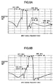
- the first band-pass filter (BPF1) 132 allows signals lying within the first band of 810-830 MHz to pass through the filter 132.
- FIG. 6A shows the insertion loss characteristics of the first band-pass filter 132.
- the second band-pass filter (BPF2) 133 allows signals lying within the second band of 870-885 MHz to pass through the filter 133.
- FIG. 6B shows the insertion loss characteristics of the second band-pass filter 133.
- the insertion loss of each of the first and second band-pass filters 132 and 133 with respect to the rejection of the out-of-band signals is set at about 30 dB.
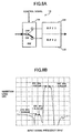
- FIG. 7A shows a first state of the band switching device 13 when the first band-pass filter 132 is connected to the input of the switch 131.
- the first state of the band switching device 13 shown in FIG. 7A, it is determined at the control circuit 40 that the received signal lies within the first band of 810-830 MHz, and the band switching device 13 is controlled by the control circuit 40 such that the received signal is passed through the filter 132.
- FIG. 7B shows the insertion loss characteristics of the band switching device 13 in the first state of FIG. 7A.
- FIG. 8A shows a second state of the band switching device 13 when the second band-pass filter 133 is connected to the input of the switch 131.
- the second state of the band switching device 13 shown in FIG. 8A, it is determined at the control circuit 40 that the received signal lies within the second band of 870-885 MHz, and the band switching device 13 is controlled by the control circuit 40 such that the received signal is passed through the filter 133.
- FIG. 8B shows the insertion loss characteristics of the band switching device 13 in the second state of FIG. 8A.
- FIG. 9 shows a configuration of the control circuit 40 in the receiver portion of the radio communication system of FIG. 2.
- control circuit 40 of the present embodiment generally comprises a band detection unit (BD) 41, a control signal generation unit (CSG) 42, an analog-to-digital converter (ADC) 43, a high-signal-strength determination unit (HSSD) 44, and a correction circuit (CRC) 45.
- BD band detection unit
- CSG control signal generation unit
- ADC analog-to-digital converter
- HSSD high-signal-strength determination unit
- CRC correction circuit
- the band detection unit 41 detects a selected one of the first and second bands (810-830 MHz and 870-885 MHz) for the received signal designating the portable telephone 10 as the destination.
- the selected band is determined by the channel control of the base station 20, and an instruction for setting the selected band in the portable telephone 10 is supplied by the base station 20.
- the band detection unit 41 detects the selected band from the supplied instruction.
- the selected band, detected by the band detection unit 41 is supplied to the control signal generation unit 42.
- the receiving-level detection unit 19 detects a received signal strength indication (RSSI) of the received signal at the output of the BPF 17, and supplies the analog signal indicative of the detected RSSI to the ADC 43.
- the ADC 43 converts the analog signal into a digital signal indicative of the detected RSSI.
- the digital signal (RSSI) is supplied from the ADC 43 to each of the correction circuit 45 and the high-signal-strength determination unit 44.
- the high-signal-strength determination unit 44 determines whether the RSSI, indicated by the digital signal output by the ADC 43, exceeds a predetermined value. The result of the determination is supplied from the HSSD 44 to the control-signal generation unit 44. Further, the high-signal-strength determination unit 44 produces an offset value according to an amount of attenuation of the received signal passed through the BSD 13, and supplies the offset value to the correction circuit 45. This offset value is used to correct an RSSI signal that is transmitted from the portable telephone 10 to the base station 20 in order to notify the base station 20 of the received signal strength indication of the portable telephone 10.
- the correction circuit 45 corrects the RSSI, indicated by the digital signal output by the ADC 43, based on the offset value sent by the HSSD 44, so that the corrected RSSI signal (digital) is produced.
- the corrected RSSI signal output by the correction circuit 45 is transmitted from the portable telephone 10 to the base station 20.
- the offset value is equal to 0 dB.
- the offset value is set to a value that substantially cancels the isolation of the switch 131 (or the insertion loss of the path in which the corresponding active element is turned OFF). In the latter case, the gain of the receiver portion is lowered due to the OFF state of the active element of the switch 131, and the offset value is added to the RSSI so as to cancel the isolation of the switch 131.
- the control signal generation unit 42 generates control signals based on the selected band output by the band detection unit 41 and based on the result of the determination output by the HSSD 44.
- the control signal generation unit 42 supplies the resulting control signals CNT1 and CNT2 to the band switching device (BSD) 13, and supplies the resulting control signals to the local oscillators LO1 and LO2.
- BSD band switching device
- the receiving-level detection unit 19 may include a distortion detection unit which detects an amount of distortion of the received signal waveform relative to a reference-distortion amount for the waveform of the received signal designating the portable telephone 10 as the destination.
- the receiving-level detection unit 19 instructs the control circuit 40 so that the control-signal generation unit 42 supplies appropriate control signals to the band switching device 13 so as to reduce the amount of distortion of the received signal waveform to a desired level through the switching of the band switching device 13.
- the receiving-level detection unit 19 and the control circuit 40 may be partially or wholly constituted by a central processing unit (CPU) or a digital signal processor (DSP).
- CPU central processing unit
- DSP digital signal processor
- the control circuit 40 changes the selected one of the outputs of the switch 131 to another output through the switching of the band switching device 13 so as to reduce the RSSI by using the selected band-pass filter having corresponding insertion-loss characteristics.
- FIG. 10 shows an operation of the band switching device 13 in a normal mode.
- the RSSI output by the ADC 43 does not exceed the predetermined value (the normal signal strength case), and the band switching device 13 operates as shown in FIG. 10.
- the switching of the selector switch 131 is controlled by the control signals CNT1 and CNT2 sent by the control circuit 40, so that the input S0 of the switch 131 is connected to the first band-pass filter (BPF1) 132 via the selected one S1 of the outputs S1 and S2 of the switch 131.
- the active element of the first transmission path (S0 - S1) is turned ON, and the active element of the second transmission path (S0 - S2) is turned OFF.
- the first band-pass filter (BPF1) 132 allows signals lying within the first band of 810 - 830 MHz to pass through the filter 132.
- the amount of attenuation with respect to the output signal of the first band-pass filter (BPF1) 132 in this case is substantially equal to the insertion loss (L11) of the switch 131 plus the insertion loss (L12) of the filter 132, which is relatively small.
- the amount of attenuation with respect to the output signal of the second band-pass filter (BPF2) 133 in this case is substantially equal to the insertion loss (L13) of the switch 131 plus the insertion loss (L14) of the filter 133, which is relatively large.
- the output signal of the entire band switching device 13 is a sum of the output signal of the first band-pass filter (BPF1) 132 and the output signal of the second band-pass filter (BPF2) 133, but the strength of the signal passed through the filter 132 is still larger than the strength of the signal passed through the filter 133.
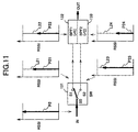
- FIG. 11 shows an operation of the band switching device 13 in a high-signal-strength mode.
- the RSSI output by the ADC 43 exceeds the predetermined value (the high signal strength case), and the band switching device 13 operates as shown in FIG. 11.
- the switching of the selector switch 131 is controlled by the control signals CNT1 and CNT2 sent by the control circuit 40, so that the input S0 of the switch 131 is connected to the second band-pass filter (BPF2) 133 via the selected one S2 of the outputs S1 and S2 of the switch 131.
- the active element of the first transmission path (S0 - S1) is turned OFF, and the active element of the second transmission path (S0 - S2) is turned ON.
- the second band-pass filter (BPF2) 133 allows signals lying within the second band of 870 - 885 MHz to pass through the filter 133.
- the amount of attenuation with respect to the output signal of the first band-pass filter (BPF1) 132 in this case is substantially equal to the insertion loss (L21) of the switch 131 plus the insertion loss (L22) of the filter 132.
- the amount of attenuation with respect to the output signal of the second band-pass filter (BPF2) 133 in this case is substantially equal to the insertion loss (L23) of the switch 131 plus the insertion loss (L24) of the filter 133.
- the output signal of the entire band switching device 13 is a sum of the output signal of the first band-pass filter (BPF1) 132 and the output signal of the second band-pass filter (BPF2) 133, and the amount of attenuation with respect to the output signal of the BSD 13 in the high-signal-strength mode is still larger than that of the BSD 13 in the normal mode.
- the control circuit 40 changes the selected one of the outputs of the switch 131 to another output through the switching of the band switching device 13 such that the RSSI (P12) in the normal mode is reduced to the RSSI (P24) in the high-signal-strength mode by using the selected band-pass filter 133 having the corresponding insertion-loss characteristics.
- the receiver portion of the portable telephone 10 and the portable telephone 10 of the present embodiment are effective in achieving a wide dynamic range without causing a distortion of the received signal waveform, by using a simple, small-size configuration.
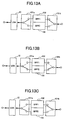
- FIG. 12 shows a change in amplitude of the output signal of the band switching device 13 which is operating in a transient region between the normal mode and the high-signal-strength mode.
- the band switching device 13 when the RSSI (the measured power of the received signal) is increased from a low level, as indicated by the dotted-line upward arrow in FIG. 12, the band switching device 13 is operating in the normal mode until the predetermined value corresponding to the switch-on point "A" is reached.
- the active element of the first transmission path (S0 - S1) in the switch 131 is turned ON, and the active element of the second transmission path (S0 - S2) is turned OFF.
- the switching of the switch 131 is performed by the control circuit 40.
- the active element of the first transmission path (S0 - S1) is turned OFF, and the active element of the second transmission path (S0 - S2) is turned ON.
- the mode of the band switching device 13 is transferred to the high-signal-strength mode.
- the amplitude of the output signal of the band switching device 13 is rapidly reduced due to the isolation of the switch 131.
- the amplitude of the output signal of the band switching device 13 is increased from the reduced point.
- the band switching device 13 is operating in the high-signal-strength mode until the predetermined value corresponding to the switch-off point "B" is reached.
- the active element of the first transmission path (S0 - S1) in the switch 131 is turned OFF, and the active element of the second transmission path (S0 - S2) is turned ON.
- the switching of the switch 131 is performed by the control circuit 40.
- the active element of the first transmission path (S0 - S1) of the switch 131 is turned ON, and the active element of the second transmission path (S0 - S2) is turned OFF.
- the mode of the band switching device 13 is transferred to the normal mode.
- the amplitude of the output signal of the band switching device 13 is rapidly raised due to the isolation of the switch 131.
- the RSSI is decreased to a low level, the amplitude of the output signal of the band switching device 13 is decreased from the raised point.
- the receiver portion of the portable telephone 10 and the portable telephone 10 of the present embodiment can easily achieve a wide dynamic range without causing a distortion of the received signal waveform, by using a simple, small-size configuration.
- the band switching device 13 serves to improve the demodulation quality of the portable telephone 10.
- the portable telephone 10 it is required for the portable telephone 10 to notify a measured power of the received signal to the base station 20.
- the correction circuit 45 is provided in the control circuit 40 to correct the RSSI, indicated by the digital signal output by the ADC 43, based on the offset value sent by the HSSD 44, so that the corrected RSSI signal is produced.
- the RSSI indicated by the digital signal output by the ADC 43
- the corrected RSSI signal produced by the correction circuit 45 is transmitted from the portable telephone 10 to the base station 20. Hence, it is possible to notify the actual power of the received signal of the portable telephone 10 to the base station 20.
- the control circuit 40 may be configured to change the selected one of the outputs of the switch 131 to another output only when a continuous time the measured power of the received signal is above the predetermined value exceeds a predetermined time. For example, a timer is provided in the control circuit 40, and the continuous time the measured power of the received signal is above the predetermined value is measured by using the timer. When the measured continuous time exceeds the predetermined time, the control circuit 40 changes the selected one of the outputs of the switch 131 to another output.
- control circuit 40 may be configured to change the selected one of the outputs of the switch 131 to another output when the measured power of the received signal exceeds a first level, and to return the selected output of the switch 131 back to the original one when the measured power of the received signal is below a second level, lower than the first level.
- the switching of the band switching device 13 is performed based on whether the RSSI is above the predetermined value.
- the switching of the band switching device 13 may be performed in synchronism with either a front-end portion or a tail-end portion of each of slots in the received signal having the specified frequency.
- the switching of the band switching device 13 is controlled so as to increase the demodulation quality of the portable telephone 10.
- the ON/OFF state of the active element of the switch 131 When the ON/OFF state of the active element of the switch 131 is set to increase the insertion loss during the normal mode operation of the band switching device 13, there is a possibility that the demodulation quality becomes degraded. Specifically, in such a case, noises or unwanted conditions may occur during conversation on the portable telephone 10. However, when the ON/OFF state of the active element of the switch 131 is set to increase the insertion loss during the high-signal-strength mode, the gain of the receiver portion will be reduced, the amount of distortion will be decreased, and the demodulation quality will be increased.
- control circuit 40 is configured to determine whether the actual demodulation quality after the switching of the switch 131 is performed is appropriate. For this purpose, the switching of the band switching device 13 is performed in synchronism with either a front-end portion or a tail-end portion of each of slots in the received signal. Hence, according to the above modification, it is possible to avoid the occurrence of a demodulation error due to the change of the ON/OFF state of the active element of the switch 131.
- the ON/OFF state of the active element of the switch 131 is changed to the opposite state so as to decrease the insertion loss.
- the above control of the control circuit 40 is performed only when the RSSI is above the predetermined value. If the ON/OFF state of the active element of the switch 131 is set to increase the insertion loss during the normal mode operation, the frame synchronization for the received signal may not be maintained.
- the ON/OFF state of the active element of the switch 131 is maintained. In this case, the execution of the switching of the switch 131 is suitable to increase the demodulation quality. Further, in the above modification, when the actual demodulation quality does not change when the switching of the switch 131 is performed, the ON/OFF state of the active element of the switch 131 is set so as to decrease the insertion loss.
- control circuit 40 is configured to confirm that the actual demodulation quality, after the switching of the switch 131 is performed in synchronism with either a front-end portion or a tail-end portion of each of slots in the received signal, is appropriate. An appropriate amount of attenuation can be maintained while checking the actual demodulation quality.
- the radio communication system and the receiver portion of the radio communication system of the present embodiment are effective in achieving a simple control of the gain of the receiver portion.
- the radio communication system of the present invention is applicable to other mobile communication systems that are different from the PDC mobile telephone system of the above-described embodiment including the portable telephone 10.
- the radio communication system of the present invention is applicable to mobile communication systems based on CDMA (code division multiple access), PHS (personal handy phone system) and GSM (global system for mobile communications) methods.
- the band switching device of the above modification operates, in the normal mode, to control the switching of the switch 135 so that the BPF1 132 is selected to pass the received signal through the filter 132.
- the band switching device of the above modification operates to control the switching of the switch 135 so that the BPF 2 133 is selected to pass the received signal through the filter 133.
- the band switching device of the above modification operates to control the switching of the switch 135 so that the terminating circuit 136 is selected to inhibit the received signal from passing through the filters 132 and 133.
- the one-input, three-output switch 135 is provided.
- a one-input, multiple-output switch having four or more outputs may be used instead.
- the RSSI is divided into three or more levels, the number of band-pass filters (BPF) is increased, and the total number of the outputs of the switch is equal to the number of the filters plus one.
- BPF band-pass filters
Landscapes
- Engineering & Computer Science (AREA)
- Computer Networks & Wireless Communication (AREA)
- Signal Processing (AREA)
- Circuits Of Receivers In General (AREA)
- Mobile Radio Communication Systems (AREA)
- Filters And Equalizers (AREA)
- Control Of Amplification And Gain Control (AREA)
- Input Circuits Of Receivers And Coupling Of Receivers And Audio Equipment (AREA)
Abstract
Description
Claims (11)
- A radio receiver apparatus comprising:a plurality of band-pass filters each allowing signals lying within a particular one of a plurality of distinct frequency bands to pass through the filter;a selector switch having an input and a plurality of outputs connected to the plurality of band-pass filters, the selector switch delivering a received signal at the input to one of the plurality of band-pass filters via a selected one of the plurality of outputs connected to said one of the plurality of band-pass filters; anda control unit controlling switching of the selector switch in accordance with both a specified frequency contained in the received signal and a receiving level of the received signal, so that the input of the selector switch is connected to the selected one of the plurality of outputs so as to pass the received signal through said one of the plurality of band-pass filters.
- A radio receiver apparatus comprising:a plurality of band-pass filters each allowing signals lying within a particular one of a plurality of distinct frequency bands to pass through the filter, the plurality of band-pass filters having insertion loss characteristics that are distinct from each other with respect to an input signal frequency;a selector switch having an input and a plurality of outputs connected to the plurality of band-pass filters, the selector switch delivering a received signal at the input to one of the plurality of band-pass filters via a selected one of the plurality of outputs connected to said one of the plurality of band-pass filters; anda control unit controlling switching of the selector switch in accordance with both a specified frequency contained in the received signal and a receiving level of the received signal, so that the input of the selector switch is connected to the selected one of the plurality of outputs so as to select one of the plurality of band-pass filters that has the insertion loss characteristics suited to the receiving level of the received signal.
- A radio receiver apparatus for receiving a signal having a specified frequency, comprising:a plurality of band-pass filters each allowing signals lying within a particular one of a plurality of distinct frequency bands to pass through the filter;a selector switch having an input and a plurality of outputs connected to the plurality of band-pass filters, the selector switch delivering a received signal at the input to one of the plurality of band-pass filters via a selected one of the plurality of outputs connected to said one of the plurality of band-pass filters; anda control unit controlling switching of the selector switch in accordance with a measured power of the received signal at an input of the control unit, so that the input of the selector switch is connected to the selected one of the plurality of outputs so as to pass the received signal through said one of the plurality of band-pass filters.
- The radio receiver apparatus according to claim 3, wherein the control unit changes the selected one of the plurality of outputs of the selector switch to another output through the switching of the selector switch when the measured power of the received signal is above a predetermined value.
- The radio receiver apparatus according to claim 3, wherein the control unit changes the selected one of the plurality of outputs of the selector switch to another output through the switching of the selector switch when a measured amount of distortion of waveform of the received signal is above a predetermined value.
- The radio receiver apparatus according to claim 3, wherein the control unit changes the selected one of the plurality of outputs of the selector switch to another output through the switching of the selector switch when a continuous time the measured power of the received signal is above a predetermined level exceeds a predetermined time.
- A radio receiver apparatus comprising:a plurality of band-pass filters each allowing signals lying within a particular one of a plurality of distinct frequency bands to pass through the filter;a selector switch having an input and a plurality of outputs connected to the plurality of band-pass filters, the selector switch delivering a received signal at the input to one of the plurality of band-pass filters via a selected one of the plurality of outputs connected to said one of the plurality of band-pass filters; anda control unit controlling switching of the selector switch in accordance with a measured power of the received signal at an input of the control unit, so that the input of the selector switch is connected to the selected one of the plurality of outputs so as to pass the received signal through said one of the plurality of band-pass filters, wherein the control unit changes the selected one of the plurality of outputs of the selector switch to another output through the switching of the selector switch when the measured power of the received signal is above a predetermined value, and wherein, after the selected output of the selector switch is changed, the received signal passed through the previously selected band-pass filter is subjected to demodulation in the radio receiver apparatus.
- A radio communication system which receives a signal having a specified frequency from a base station, measures a power of the received signal, and transmits a notification indicative of the measured power of the received signal, to the base station, comprising:a plurality of band-pass filters each allowing signals lying within a particular one of a plurality of distinct frequency bands to pass through the filter;a selector switch having an input and a plurality of outputs connected to the plurality of band-pass filters, the selector switch delivering a received signal at the input to one of the plurality of band-pass filters via a selected one of the plurality of outputs connected to said one of the plurality of band-pass filters; anda control unit controlling switching of the selector switch in accordance with a measured power of the received signal at an input of the control unit, so that the input of the selector switch is connected to the selected one of the plurality of outputs so as to pass the received signal through said one of the plurality of band-pass filters, wherein the control unit includes a correction unit adding an offset value, produced according to an amount of attenuation of the received signal passed through the selected filter, to the measured power of the received signal.
- A method of controlling a gain of a radio receiver apparatus, comprising the steps of:providing a plurality of band-pass filters each allowing signals lying within a particular one of a plurality of distinct frequency bands to pass through the filter;providing a selector switch having an input and a plurality of outputs connected to the plurality of band-pass filters, the selector switch delivering a received signal at the input to one of the plurality of band-pass filters via a selected one of the plurality of outputs connected to said one of the plurality of band-pass filters;measuring a power of the received signal; andcontrolling switching of the selector switch in accordance with the measured power of the received signal, so that the input of the selector switch is connected to the selected one of the plurality of outputs so as to pass the received signal through said one of the plurality of band-pass filters.
- A method of controlling a gain of a receiver portion of a radio communication system that receives a signal having a specified frequency, comprising the steps of:providing a plurality of band-pass filters each allowing signals lying within a particular one of a plurality of distinct frequency bands to pass through the filter, the plurality of band-pass filters having insertion loss characteristics that are distinct from each other with respect to an input signal frequency;providing a selector switch having an input and a plurality of outputs connected to the plurality of band-pass filters, the selector switch delivering a received signal at the input to one of the plurality of band-pass filters via a selected one of the plurality of outputs connected to said one of the plurality of band-pass filters;detecting the specified frequency contained in the received signal and a receiving level of the received signal at an output of said one of the plurality of band-pass filters; andcontrolling switching of the selector switch in accordance with both the specified frequency contained in the received signal and the receiving level of the received signal, so that the input of the selector switch is connected to the selected one of the plurality of outputs so as to select one of the plurality of band-pass filters that has the insertion loss characteristics suited to the receiving level of the received signal, and to vary an amount of attenuation for the received signal by using the selected band-pass filter.
- The method according to claim 10, wherein, in said controlling step, the switching of the selector switch is performed in synchronism with either a front-end portion or a tail-end portion of each of slots in the received signal having the specified frequency.
Applications Claiming Priority (2)
| Application Number | Priority Date | Filing Date | Title |
|---|---|---|---|
| JP30725999A JP2001127660A (en) | 1999-10-28 | 1999-10-28 | Radio communication device and gain control method of reception system |
| JP30725999 | 1999-10-28 |
Publications (3)
| Publication Number | Publication Date |
|---|---|
| EP1096697A2 true EP1096697A2 (en) | 2001-05-02 |
| EP1096697A3 EP1096697A3 (en) | 2003-11-05 |
| EP1096697B1 EP1096697B1 (en) | 2005-02-09 |
Family
ID=17966963
Family Applications (1)
| Application Number | Title | Priority Date | Filing Date |
|---|---|---|---|
| EP20000122203 Expired - Lifetime EP1096697B1 (en) | 1999-10-28 | 2000-10-13 | Radio communication system and method for controlling a gain of a receiver portion of the system |
Country Status (3)
| Country | Link |
|---|---|
| EP (1) | EP1096697B1 (en) |
| JP (1) | JP2001127660A (en) |
| DE (1) | DE60018012T2 (en) |
Cited By (1)
| Publication number | Priority date | Publication date | Assignee | Title |
|---|---|---|---|---|
| WO2002091569A1 (en) * | 2001-05-08 | 2002-11-14 | Nokia Corporation | Gain adjusting and circuit arrangement |
Families Citing this family (3)
| Publication number | Priority date | Publication date | Assignee | Title |
|---|---|---|---|---|
| KR100431196B1 (en) * | 2001-12-20 | 2004-05-12 | 한국전자통신연구원 | An Automatic Gain Control Circuit of Multi-band Modem |
| JP2010074395A (en) * | 2008-09-17 | 2010-04-02 | Sharp Corp | Tuner module for receiving tv broadcast, and tv broadcast receiver with the same |
| JP6575848B2 (en) * | 2015-03-13 | 2019-09-18 | Necネットワーク・センサ株式会社 | Reception device, communication system, and reception method |
Family Cites Families (10)
| Publication number | Priority date | Publication date | Assignee | Title |
|---|---|---|---|---|
| CA1190289A (en) * | 1981-04-28 | 1985-07-09 | Nippon Hoso Kyokai | Fm signal demodulation system |
| US4539526A (en) * | 1983-01-31 | 1985-09-03 | Dbx, Inc. | Adaptive signal weighting system |
| DE4208605A1 (en) * | 1992-03-18 | 1993-09-23 | Blaupunkt Werke Gmbh | CIRCUIT ARRANGEMENT FOR NEXT CHANNEL RECOGNITION AND SUPPRESSION IN A BROADCAST RECEIVER |
| DE4319457C2 (en) * | 1993-06-11 | 1997-09-04 | Blaupunkt Werke Gmbh | Circuit arrangement for adjacent channel detection and suppression in an FM radio receiver |
| JPH0766744A (en) * | 1993-08-30 | 1995-03-10 | Nec Corp | Electric field detection circuit |
| JPH08154062A (en) * | 1994-11-28 | 1996-06-11 | Nec Corp | Band switched receiving system using signal quality |
| JPH0936799A (en) * | 1995-07-21 | 1997-02-07 | Toshiba Corp | Wireless communication device |
| US5752179A (en) * | 1995-08-17 | 1998-05-12 | Zenith Electronics Corporation | Selective RF circuit with varactor tuned and switched bandpass filters |
| US5852772A (en) * | 1997-02-25 | 1998-12-22 | Ericsson Inc. | Receiver IF system with active filters |
| US6047171A (en) * | 1998-01-08 | 2000-04-04 | Ericsson Inc. | Method and apparatus for combating adjacent channel interference using multiple IF filters |
-
1999
- 1999-10-28 JP JP30725999A patent/JP2001127660A/en not_active Withdrawn
-
2000
- 2000-10-13 EP EP20000122203 patent/EP1096697B1/en not_active Expired - Lifetime
- 2000-10-13 DE DE2000618012 patent/DE60018012T2/en not_active Expired - Fee Related
Cited By (4)
| Publication number | Priority date | Publication date | Assignee | Title |
|---|---|---|---|---|
| WO2002091569A1 (en) * | 2001-05-08 | 2002-11-14 | Nokia Corporation | Gain adjusting and circuit arrangement |
| US6980051B2 (en) | 2001-05-08 | 2005-12-27 | Nokia Corporation | Gain adjusting and circuit arrangement |
| US7170350B2 (en) | 2001-05-08 | 2007-01-30 | Nokia Corporation | Gain adjusting and circuit arrangement |
| US7714654B2 (en) | 2001-05-08 | 2010-05-11 | Nokia Corporation | Amplifier and amplifier gain adjustment circuitry using current steering, and multimode communication device containing same |
Also Published As
| Publication number | Publication date |
|---|---|
| JP2001127660A (en) | 2001-05-11 |
| DE60018012D1 (en) | 2005-03-17 |
| EP1096697B1 (en) | 2005-02-09 |
| DE60018012T2 (en) | 2005-12-29 |
| EP1096697A3 (en) | 2003-11-05 |
Similar Documents
| Publication | Publication Date | Title |
|---|---|---|
| US6603810B1 (en) | Combined system for calibrating receiver gain and measuring antenna impedance match and method of operation | |
| US9026070B2 (en) | Low-power wireless diversity receiver with multiple receive paths | |
| KR100949863B1 (en) | Direct conversion of low power high linearity receiver | |
| US7415254B2 (en) | Power control circuit, semiconductor device and transceiver circuit using the same | |
| US7444166B2 (en) | Wireless diversity receiver with shared receive path | |
| KR100746608B1 (en) | Apparatus for increasing receiver sensitivity of receiver for direct conversion, and related methods | |
| US6298221B1 (en) | Adaptive receiver linearity techniques for a radio transceiver | |
| US20070242784A1 (en) | Diversity receiver for wireless communication | |
| US8081943B2 (en) | Reception apparatus and reception method | |
| US20090154377A1 (en) | Wireless Communication Apparatus | |
| EP0785640B1 (en) | Method for extending the RSSI range and radio transceiver operating in accordance with this method | |
| JP2007505591A (en) | Multi-mode radio with interference cancellation circuit | |
| US6510310B1 (en) | Dual mode phone architecture utilizing a single transmit-receive switch | |
| GB2258122A (en) | Detecting intermodulation distortion in a radio frequency receiver | |
| JP2007529181A (en) | Multi-mode / multi-band mobile station and method of operating the mobile station | |
| US20100238844A1 (en) | Multiband wireless communication method and multiband wireless communication apparatus | |
| US6741640B1 (en) | System and method for measuring the return loss of an antenna | |
| US8798552B2 (en) | Reconfigurable wireless transceiver | |
| EP1096697B1 (en) | Radio communication system and method for controlling a gain of a receiver portion of the system | |
| RU2211532C2 (en) | Method and device for enhancing noise immunity | |
| JPH09181660A (en) | Wireless terminal | |
| US6785324B1 (en) | Transceiver including reactive termination for enhanced cross-modulation performance and related methods | |
| EP4406125B1 (en) | System and method for power amplifier control in a millimeter wave communication system | |
| KR100267190B1 (en) | Apparatus of front-end for down frequency converter of mobile communication base station | |
| JP2000299643A (en) | Receiver |
Legal Events
| Date | Code | Title | Description |
|---|---|---|---|
| PUAI | Public reference made under article 153(3) epc to a published international application that has entered the european phase |
Free format text: ORIGINAL CODE: 0009012 |
|
| AK | Designated contracting states |
Kind code of ref document: A2 Designated state(s): AT BE CH CY DE DK ES FI FR GB GR IE IT LI LU MC NL PT SE |
|
| AX | Request for extension of the european patent |
Free format text: AL;LT;LV;MK;RO;SI |
|
| RIC1 | Information provided on ipc code assigned before grant |
Ipc: 7H 04B 1/10 B Ipc: 7H 03D 3/00 B Ipc: 7H 04B 7/08 A |
|
| PUAL | Search report despatched |
Free format text: ORIGINAL CODE: 0009013 |
|
| RIC1 | Information provided on ipc code assigned before grant |
Ipc: 7H 03G 3/20 B Ipc: 7H 04B 1/10 B Ipc: 7H 03D 3/00 B Ipc: 7H 04B 7/08 A |
|
| AK | Designated contracting states |
Kind code of ref document: A3 Designated state(s): AT BE CH CY DE DK ES FI FR GB GR IE IT LI LU MC NL PT SE |
|
| AX | Request for extension of the european patent |
Extension state: AL LT LV MK RO SI |
|
| 17P | Request for examination filed |
Effective date: 20031205 |
|
| 17Q | First examination report despatched |
Effective date: 20040122 |
|
| AKX | Designation fees paid |
Designated state(s): DE FR GB |
|
| GRAP | Despatch of communication of intention to grant a patent |
Free format text: ORIGINAL CODE: EPIDOSNIGR1 |
|
| GRAS | Grant fee paid |
Free format text: ORIGINAL CODE: EPIDOSNIGR3 |
|
| GRAA | (expected) grant |
Free format text: ORIGINAL CODE: 0009210 |
|
| AK | Designated contracting states |
Kind code of ref document: B1 Designated state(s): DE FR GB |
|
| REG | Reference to a national code |
Ref country code: GB Ref legal event code: FG4D |
|
| REG | Reference to a national code |
Ref country code: IE Ref legal event code: FG4D |
|
| REF | Corresponds to: |
Ref document number: 60018012 Country of ref document: DE Date of ref document: 20050317 Kind code of ref document: P |
|
| PG25 | Lapsed in a contracting state [announced via postgrant information from national office to epo] |
Ref country code: GB Free format text: LAPSE BECAUSE OF NON-PAYMENT OF DUE FEES Effective date: 20051013 |
|
| PLBE | No opposition filed within time limit |
Free format text: ORIGINAL CODE: 0009261 |
|
| STAA | Information on the status of an ep patent application or granted ep patent |
Free format text: STATUS: NO OPPOSITION FILED WITHIN TIME LIMIT |
|
| ET | Fr: translation filed | ||
| 26N | No opposition filed |
Effective date: 20051110 |
|
| PG25 | Lapsed in a contracting state [announced via postgrant information from national office to epo] |
Ref country code: DE Free format text: LAPSE BECAUSE OF NON-PAYMENT OF DUE FEES Effective date: 20060503 |
|
| GBPC | Gb: european patent ceased through non-payment of renewal fee |
Effective date: 20051013 |
|
| PG25 | Lapsed in a contracting state [announced via postgrant information from national office to epo] |
Ref country code: FR Free format text: LAPSE BECAUSE OF NON-PAYMENT OF DUE FEES Effective date: 20051031 |
|
| REG | Reference to a national code |
Ref country code: FR Ref legal event code: ST Effective date: 20110531 |