EP1096610A1 - Electrical connector assembly - Google Patents
Electrical connector assembly Download PDFInfo
- Publication number
- EP1096610A1 EP1096610A1 EP00123128A EP00123128A EP1096610A1 EP 1096610 A1 EP1096610 A1 EP 1096610A1 EP 00123128 A EP00123128 A EP 00123128A EP 00123128 A EP00123128 A EP 00123128A EP 1096610 A1 EP1096610 A1 EP 1096610A1
- Authority
- EP
- European Patent Office
- Prior art keywords
- shield
- terminals
- housing
- different orientations
- electrical connector
- Prior art date
- Legal status (The legal status is an assumption and is not a legal conclusion. Google has not performed a legal analysis and makes no representation as to the accuracy of the status listed.)
- Withdrawn
Links
- 239000000758 substrate Substances 0.000 claims abstract description 26
- 239000002184 metal Substances 0.000 claims abstract description 24
- 230000013011 mating Effects 0.000 claims description 19
- 230000000295 complement effect Effects 0.000 claims description 12
- 238000004519 manufacturing process Methods 0.000 description 3
- 239000007769 metal material Substances 0.000 description 3
- 238000005476 soldering Methods 0.000 description 2
- 239000011800 void material Substances 0.000 description 2
- 230000008602 contraction Effects 0.000 description 1
- 239000000463 material Substances 0.000 description 1
- 239000007787 solid Substances 0.000 description 1
Images


Classifications
-
- H—ELECTRICITY
- H01—ELECTRIC ELEMENTS
- H01R—ELECTRICALLY-CONDUCTIVE CONNECTIONS; STRUCTURAL ASSOCIATIONS OF A PLURALITY OF MUTUALLY-INSULATED ELECTRICAL CONNECTING ELEMENTS; COUPLING DEVICES; CURRENT COLLECTORS
- H01R12/00—Structural associations of a plurality of mutually-insulated electrical connecting elements, specially adapted for printed circuits, e.g. printed circuit boards [PCB], flat or ribbon cables, or like generally planar structures, e.g. terminal strips, terminal blocks; Coupling devices specially adapted for printed circuits, flat or ribbon cables, or like generally planar structures; Terminals specially adapted for contact with, or insertion into, printed circuits, flat or ribbon cables, or like generally planar structures
- H01R12/70—Coupling devices
- H01R12/71—Coupling devices for rigid printing circuits or like structures
- H01R12/72—Coupling devices for rigid printing circuits or like structures coupling with the edge of the rigid printed circuits or like structures
- H01R12/721—Coupling devices for rigid printing circuits or like structures coupling with the edge of the rigid printed circuits or like structures cooperating directly with the edge of the rigid printed circuits
Definitions
- This invention generally relates to the art of electrical connectors and, particularly, to an electrical connector assembly or system wherein the individual components of an electrical connector can be assembled in multiple different orientations to provide different configurations of electrical connectors.
- an electrical connector includes some form of dielectric housing which mounts a plurality of conductive terminals.
- the housing may be mounted in a casing, such as a metal shield which protects the mating interface of the connector from electromagnetic or radio frequency interferences.
- Electrical connectors of this general type are used in a wide variety of applications, including mounting on printed circuit boards. Consequently, such connectors are provided in a wide variety of configurations, orientations and directional matings to accommodate a myriad of electrical functions.
- a printed circuit board mounted electrical connector might be mounted on either side of the printed circuit board.
- a different connector must be provided for mounting on one side of the board versus mounting on the opposite side.
- connector Even if the connector is not a board mounted connector, discrete connector components, such as the connector housings, terminals, metal shells or the like, often must be changed to create problems that are very similar in function but are used in different orientations. With a board mounted connector, terminals often must be oriented in different directions relative to the soldering plane of the board.
- An object, therefore, of the invention is to provide a new and improved electrical connector assembly of the character described.
- Another object of the invention is to provide a new and improved board mounted electrical connector system.
- a further object of the invention is to provide such a system wherein the components of a connector can be assembled in multiple orientations to provide multiple different connector configurations.
- the electrical connector assembly or system includes a metal shield having a cavity and which is mountable on a substrate in at least two different orientations.
- a dielectric housing is mountable within the cavity in the shield in at least two different orientations for each orientation of the shield.
- a plurality of terminals are mountable on the housing in at least two different orientations for each orientation of the housing. Therefore, the total combinations of different orientations of the metal shield, the dielectric housing and the conductive terminals effectively provide at least eight different configurations of electrical connectors utilizing the same connector components.
- the metal shield has two sides, either of which is mountable on the substrate, and only one of which has an open seam.
- the shield can be mounted in one orientation with the seamed side away from the substrate to provide resiliency for the shield, and in a second orientation with the seamed side against the substrate to provide substantially complete shielding at the sides of the shield away from the substrate.
- the housing includes polarizing means so that a complementary connector can mate with the housing in only one orientation. Therefore, the mating connector has at least two different orientations relative to the shield.
- the terminals are generally U-shaped to define a pair of leg portions joined by a bight portion. Only one of the leg portions of each terminal has a terminating portion whereby the terminating portions are located at different positions relative to the housing corresponding to the at least two different orientations of the terminals.
- the bight portions of the terminals comprise contact portions for engaging appropriate contact portions of a plurality of terminals of a complementary mating connector.
- the substrate may be a printed circuit board, and the terminating portions of the terminals, therefore, comprise tail portions for connection to appropriate circuit traces on the printed circuit board.
- an electrical connector assembly generally designated 10 which includes a metal shell or shield, generally designated 12; a dielectric housing, generally designated 14; and a plurality of conductive terminals, generally designated 16.
- connector assembly 10 When terminals 16 are mounted on housing 14, and the housing is mounted within shield 12, connector assembly 10 includes a front mating face 18 and a rear terminating face 20.
- metal shield 12 is stamped and formed of conductive sheet metal material.
- the shield is generally rectangularly shaped to define an elongated cavity, generally designated 22, for receiving housing 14.
- the cavity is bounded by two major or elongated sides 24 and 26 and a pair of minor or narrow ends 28.
- the sheet metal material is folded into the rectangular configuration and a pair of opposing ends of the sheet metal material abut at a seam 30 as seen clearly in Figure 7.
- a pair of latch openings 32 are provided at opposite ends of each elongated side 24 and 26 for interengagement with appropriate latches of a complementary mating connector (not shown).
- elongated side 26 has open seam 30 therein, while elongated side 24 is void of any seam.
- Both sides 24 and 26 are planar, and shield 12 is adapted for fixing to a surface of a planar substrate, such as a printed circuit board.
- the metal shield can be soldered to appropriate pads on the board, for instance.
- the shield is mountable on the board in either of two different orientations. First, the shield can be mounted as shown in Figures 1 and 7, with side 26 and seam 30 located against the board. In this orientation, elongated side 24 and ends 28 are void of any seams and, thereby, provide substantially complete shielding about all sides of the connector except the bottom side mounted to the board.
- shield 12 it may be desirable to provide shield 12 with a degree of flexibility, whereupon the shield can be mounted to the board with elongated side 24 at the bottom of the connector and against the board, as will be seen hereinafter.
- this second orientation with open seam 30 being at the top of the connector rather than at the fixed bottom side of the connector, expansion and contraction or resiliency for top side 26 of the shield is provided.
- dielectric housing 14 is a one-piece structure unitarily molded of plastic material or the like.
- the housing includes an elongated body portion 34 extending between a pair of end wing portions 36.
- a plurality of wrap-around channels 38 are formed by a plurality of ribs 40 which are spaced longitudinally of body portion 34.
- ribs 40 project outwardly from body portion 34 on opposite sides and a front thereof so that channels 38 are generally U-shaped.
- a pair of arms 42 project forwardly of wing portions 36 and are formed with polarizing grooves 44 so that the complementary connector can mate with the housing in only one direction.
- the housing is insertable into cavity 22 in metal shield 12 in two different orientations. Therefore, the mating connector also will have two different orientations relative to shield 12.
- each terminal 16 is generally U-shaped to define a pair of leg portions 46 and 48 joined by a bight portion 50.
- the bight portion forms a contact portion of the terminal, with a front face 50a of the bight portion engageable with an appropriate contact portion of one of a plurality of terminals of the complementary mating connector.
- the rear end of leg portion 46 of each terminal is provided with an offset tail 52 for connection, as by soldering, to an appropriate circuit trace on the printed circuit board.
- the tail is offset so that it is flush with whatever major side 24 or 26 of shield 12 is fixed to the board.
- U-shaped terminals 16 are mountable in U-shaped channels 38 of housing 14 in either one of two different orientations, as will be seen hereinafter.
- shield 12 can be mounted on a substrate, such as a printed circuit board, with seamed side 26 thereof being the bottom the shield and mounted on the substrate in the orientation shown in Figure 1.
- the shield can be inverted to mount solid side 24 onto the substrate to afford two different connector configurations for two different functional purposes as described above.
- Housing 14 is inserted into cavity 22 in the shield in the direction of arrow "A" (Fig. 1) with polarizing grooves 44 facing upwardly as shown.
- the housing can be inverted so that the polarizing grooves face downwardly.
- terminals 16 can be mounted on housing 14 in the direction of arrow "B" in two different orientations, i.e., with tails 52 projecting downwardly as shown, or with the terminals inverted so that the tails project upwardly. Adding these two different orientations of the terminals to the different orientations of the housing and the shield, it can be understood that electrical connector 10 can be provided in eight completely different configurations.
- shield 12 is in the same orientation with seamed side 26 oriented downwardly for mounting on a substrate in both Figures 1 and 4.
- housing 14 as well as terminals 16 all have been inverted in Figure 4 versus their orientations in Figure 1.
- polarizing grooves 44 of the housing face downwardly in Figure 4 rather than upwardly as in Figure 1
- tails 52 of the terminals project upwardly in Figure 4 rather than downwardly as in Figure 1.
Landscapes
- Details Of Connecting Devices For Male And Female Coupling (AREA)
- Coupling Device And Connection With Printed Circuit (AREA)
Abstract
An electrical connector system (10) includes a metal shield (12) having a cavity (22) and being mountable on a substrate in at least two different orientations. A dielectric housing (14) is mountable within the cavity (22) in the shield (12) in at least two different orientations for each orientation of the shield. A plurality of conductive terminals (16) are mountable on the housing (14) in at least two different orientations for each orientation of the housing. Therefore, the total combinations of different orientations of the metal shield (12), the dielectric housing (14) and the conductive terminals (16) effectively provide at least eight different configurations of electrical connectors. <IMAGE>
Description
This invention generally relates to the art of electrical connectors and,
particularly, to an electrical connector assembly or system wherein the individual
components of an electrical connector can be assembled in multiple different orientations
to provide different configurations of electrical connectors.
Generally, an electrical connector includes some form of dielectric
housing which mounts a plurality of conductive terminals. The housing may be mounted
in a casing, such as a metal shield which protects the mating interface of the connector
from electromagnetic or radio frequency interferences. Electrical connectors of this
general type are used in a wide variety of applications, including mounting on printed
circuit boards. Consequently, such connectors are provided in a wide variety of
configurations, orientations and directional matings to accommodate a myriad of
electrical functions.
For example, a printed circuit board mounted electrical connector might
be mounted on either side of the printed circuit board. However, if it is desired to
preserve the mating orientation of the connector with a complementary mating connector
for aesthetic or functional reasons, a different connector must be provided for mounting
on one side of the board versus mounting on the opposite side.
Even if the connector is not a board mounted connector, discrete
connector components, such as the connector housings, terminals, metal shells or the
like, often must be changed to create problems that are very similar in function but are
used in different orientations. With a board mounted connector, terminals often must be
oriented in different directions relative to the soldering plane of the board.
In order to accommodate mass production of such electrical connectors,
it often is required to provide very similar tooling but which is slightly changed to
manufacture a plurality of slightly different connectors, such as described above. This
near-duplication in tooling significantly increases the manufacturing cost of the
connectors by increasing capital expenditures for molds, dies and assembly tools. In
addition, tool utilization and output yield rates may vary significantly in relation to the
demands for specific product versions. Inventory costs of different connectors also adds
to the individual costs thereof. The logistics of warehousing components that may be
very difficult to distinguish visually requires multiple (redundant) checks and balances
to assure that the correct products are delivered as requested. The present invention is
directed to solving these many problems by providing an electrical connector system
wherein a plurality of connector components can be assembled in multiple orientations
to provide multiple different configurations of electrical connectors.
An object, therefore, of the invention is to provide a new and improved
electrical connector assembly of the character described.
Another object of the invention is to provide a new and improved board
mounted electrical connector system.
A further object of the invention is to provide such a system wherein the
components of a connector can be assembled in multiple orientations to provide multiple
different connector configurations.
In the exemplary embodiment of the invention, the electrical connector
assembly or system includes a metal shield having a cavity and which is mountable on
a substrate in at least two different orientations. A dielectric housing is mountable
within the cavity in the shield in at least two different orientations for each orientation
of the shield. A plurality of terminals are mountable on the housing in at least two
different orientations for each orientation of the housing. Therefore, the total
combinations of different orientations of the metal shield, the dielectric housing and the
conductive terminals effectively provide at least eight different configurations of
electrical connectors utilizing the same connector components.
As disclosed herein, the metal shield has two sides, either of which is
mountable on the substrate, and only one of which has an open seam. The shield can be
mounted in one orientation with the seamed side away from the substrate to provide
resiliency for the shield, and in a second orientation with the seamed side against the
substrate to provide substantially complete shielding at the sides of the shield away from
the substrate.
The housing includes polarizing means so that a complementary
connector can mate with the housing in only one orientation. Therefore, the mating
connector has at least two different orientations relative to the shield.
The terminals are generally U-shaped to define a pair of leg portions
joined by a bight portion. Only one of the leg portions of each terminal has a terminating
portion whereby the terminating portions are located at different positions relative to the
housing corresponding to the at least two different orientations of the terminals. The
bight portions of the terminals comprise contact portions for engaging appropriate
contact portions of a plurality of terminals of a complementary mating connector. The
substrate may be a printed circuit board, and the terminating portions of the terminals,
therefore, comprise tail portions for connection to appropriate circuit traces on the
printed circuit board.
Other objects, features and advantages of the invention will be apparent
from the following detailed description taken in connection with the accompanying
drawings.
The features of this invention which are believed to be novel are set forth
with particularity in the appended claims. The invention, together with its objects and
the advantages thereof, may be best understood by reference to the following description
taken in conjunction with the accompanying drawings, in which like reference numerals
identify like elements in the figures and in which:
Referring to the drawings in greater detail, and first to Figure 1, the
invention is embodied in an electrical connector assembly, generally designated 10,
which includes a metal shell or shield, generally designated 12; a dielectric housing,
generally designated 14; and a plurality of conductive terminals, generally designated 16.
When terminals 16 are mounted on housing 14, and the housing is mounted within shield
12, connector assembly 10 includes a front mating face 18 and a rear terminating face 20.
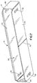
Referring to Figure 7 in conjunction with Figure 1, metal shield 12 is
stamped and formed of conductive sheet metal material. The shield is generally
rectangularly shaped to define an elongated cavity, generally designated 22, for receiving
housing 14. The cavity is bounded by two major or elongated sides 24 and 26 and a pair
of minor or narrow ends 28. In forming the metal shield, the sheet metal material is
folded into the rectangular configuration and a pair of opposing ends of the sheet metal
material abut at a seam 30 as seen clearly in Figure 7. A pair of latch openings 32 are
provided at opposite ends of each elongated side 24 and 26 for interengagement with
appropriate latches of a complementary mating connector (not shown).
With the above description of metal shield 12, it can be seen that
elongated side 26 has open seam 30 therein, while elongated side 24 is void of any seam.
Both sides 24 and 26 are planar, and shield 12 is adapted for fixing to a surface of a
planar substrate, such as a printed circuit board. The metal shield can be soldered to
appropriate pads on the board, for instance. The shield is mountable on the board in
either of two different orientations. First, the shield can be mounted as shown in Figures
1 and 7, with side 26 and seam 30 located against the board. In this orientation,
elongated side 24 and ends 28 are void of any seams and, thereby, provide substantially
complete shielding about all sides of the connector except the bottom side mounted to
the board. Second, it may be desirable to provide shield 12 with a degree of flexibility,
whereupon the shield can be mounted to the board with elongated side 24 at the bottom
of the connector and against the board, as will be seen hereinafter. In this second
orientation, with open seam 30 being at the top of the connector rather than at the fixed
bottom side of the connector, expansion and contraction or resiliency for top side 26 of
the shield is provided.
Referring to Figure 6 in conjunction with Figure 1, dielectric housing 14
is a one-piece structure unitarily molded of plastic material or the like. The housing
includes an elongated body portion 34 extending between a pair of end wing portions 36.
A plurality of wrap-around channels 38 are formed by a plurality of ribs 40 which are
spaced longitudinally of body portion 34. In essence, ribs 40 project outwardly from
body portion 34 on opposite sides and a front thereof so that channels 38 are generally
U-shaped. Finally, a pair of arms 42 project forwardly of wing portions 36 and are
formed with polarizing grooves 44 so that the complementary connector can mate with
the housing in only one direction. However, as will be seen hereinafter, the housing is
insertable into cavity 22 in metal shield 12 in two different orientations. Therefore, the
mating connector also will have two different orientations relative to shield 12.
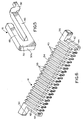
Referring to Figure 5 in conjunction with Figure 4, each terminal 16 is
generally U-shaped to define a pair of leg portions 46 and 48 joined by a bight portion
50. The bight portion forms a contact portion of the terminal, with a front face 50a of
the bight portion engageable with an appropriate contact portion of one of a plurality of
terminals of the complementary mating connector. The rear end of leg portion 46 of
each terminal is provided with an offset tail 52 for connection, as by soldering, to an
appropriate circuit trace on the printed circuit board. The tail is offset so that it is flush
with whatever major side 24 or 26 of shield 12 is fixed to the board. U-shaped terminals
16 are mountable in U-shaped channels 38 of housing 14 in either one of two different
orientations, as will be seen hereinafter.
Referring back to Figure 1, and before proceeding with a description of
the different assembly combinations of connector 10 in relation to Figures 2-4, it can be
recapitulated that shield 12 can be mounted on a substrate, such as a printed circuit
board, with seamed side 26 thereof being the bottom the shield and mounted on the
substrate in the orientation shown in Figure 1. Alternatively, the shield can be inverted
to mount solid side 24 onto the substrate to afford two different connector configurations
for two different functional purposes as described above. Housing 14 is inserted into
cavity 22 in the shield in the direction of arrow "A" (Fig. 1) with polarizing grooves 44
facing upwardly as shown. Alternatively, the housing can be inverted so that the
polarizing grooves face downwardly. These two different orientations of the housing, in
combination with the two different orientations of shield 12, provide four different
configurations of electrical connectors. Continuing on, terminals 16 can be mounted on
housing 14 in the direction of arrow "B" in two different orientations, i.e., with tails 52
projecting downwardly as shown, or with the terminals inverted so that the tails project
upwardly. Adding these two different orientations of the terminals to the different
orientations of the housing and the shield, it can be understood that electrical connector
10 can be provided in eight completely different configurations.
This multiple configuration connector system can best be understood by
comparing Figures 1-4. For instance, in comparing Figure 2 with Figure 1, it can be seen
that shield 12 has been inverted so that seamed side 26 faces upwardly in Figure 2 versus
the downward orientation of Figure 1. Likewise, housing 14 has been inverted in Figure
2 versus the orientation of Figure 1, so that polarizing grooves 44 of the housing face
downwardly in Figure 2 rather than upwardly as in Figure 1. Terminals 16 have the
same orientations in both Figures 1 and 2.
Comparing Figure 3 with Figure 1, it can be seen that shield 12 and
housing 14 both are in the same orientations in both depictions. In other words, seamed
side 26 of the shield faces downwardly and polarizing grooves 44 of the housing face
upwardly in both Figures 1 and 3. However, it can be seen that terminals 16 have been
inverted so that tails 52 project upwardly in Figure 3 rather than downwardly as in Figure
1.
Comparing Figure 4 with Figure 1, it can be seen that shield 12 is in the
same orientation with seamed side 26 oriented downwardly for mounting on a substrate
in both Figures 1 and 4. However, housing 14 as well as terminals 16 all have been
inverted in Figure 4 versus their orientations in Figure 1. In other words, polarizing
grooves 44 of the housing face downwardly in Figure 4 rather than upwardly as in Figure
1, and tails 52 of the terminals project upwardly in Figure 4 rather than downwardly as
in Figure 1.
From the foregoing comparison of Figures 1-4, it can be understood that
with the two different possible orientations of metal shield 12, in combination with the
two different possible orientations of housing 14 and the two different possible
orientations of terminals 16, eight different configurations of electrical connectors can
be provided with the identical three components, namely the shield, the housing and the
identical terminals. Such a system significantly reduces the costs of molds, dies and
assembly tools as well as the costs of having an inventory of eight different connectors,
along with the logistics problems of delivering eight different connectors with varying
demands.
It will be understood that the invention may be embodied in other specific
forms without departing from the spirit or central characteristics thereof. The present
examples and embodiments, therefore, are to be considered in all respects as illustrative
and not restrictive, and the invention is not to be limited to the details given herein.
Claims (18)
- An electrical connector system (10), comprising:a metal shield (12) having a cavity (22) and being mountable on a substrate in at least two different orientations;a dielectric housing (14) mountable within the cavity (22) in the shield (12) in at least two different orientations for each orientation of the shield;a plurality of conductive terminals (16) mountable on the housing (14) in at least two different orientations for each orientation of the housing;
whereby the total combinations of different orientations of the metal shield (12), the dielectric housing (14) and the conductive terminals (16) effectively provide at least eight different configurations of electrical connectors. - The electrical connector system of claim 1 wherein said metal shield (12) has two sides (24,26) either of which is mountable on the substrate and only one (26) of which has an open seam (30), whereby the shield can be mounted in one orientation with the seamed side (26) away from the substrate to provide resiliency for the shield and in a second orientation with the seamed side (26) against the substrate to provide substantially complete shielding at the sides (24,28) of the shield (12) away from the substrate.
- The electrical connector system of claim 1 wherein said dielectric housing (14) includes polarizing means (44) so that a complementary mating connector can mate with the housing in only one orientation, the mating connector thereby having said at least two different orientations relative to the shield (12).
- The electrical connector system of claim 1 wherein said terminals (16) are generally U-shaped to define a pair of leg portions (46,48) joined by a bight portion (50), only one (46) of the leg portions of each terminal having a terminating portion (52) whereby the terminating portions are located at different positions relative to the housing corresponding to said at least two different orientations of the terminals.
- The electrical connector system of claim 4 wherein said bight portions (50) of the terminals (16) comprise contact portions (50a) for engaging appropriate contact portions of a plurality of terminals of a complementary mating connector.
- The electrical connector system of claim 4 wherein said terminating portions (52) of the terminals comprise tail portions for connection to appropriate circuit traces on a printed circuit board.
- An electrical connector system (10), comprising:a metal shield (12) having a cavity (22) and at least two opposite sides (24,26) either of which is mountable on a substrate and only one (26) of which has an open seam (30), whereby the shield can be mounted in one orientation with the seamed side (26) away from the substrate to provide resiliency for the shield and in a second orientation with the seamed side (26) against the substrate to provide substantially complete shielding at the sides (24,28) of the shield (12) away from the substrate;a dielectric housing (14) mountable within the cavity (12) in the shield (12) in at least two different orientations for each orientation of the shield;a plurality of conductive terminals (16) mountable on the housing;
whereby the total combinations of different orientations of the metal shield (12) and the dielectric housing (14) provide at least four different configurations of electrical connectors. - The electrical connector system of claim 7 wherein said dielectric housing (14) includes polarizing means (44) so that a complementary mating connector can mate with the housing in only one orientation, the mating connector thereby having said at least two different orientations relative to the shield (12).
- An electrical connector system (10), comprising:a metal shield (12) having a cavity (22);a dielectric housing (14) mountable within the cavity (22) in the shield in at least two different orientations; anda plurality of conductive terminals (16) mountable on the housing (14) in at least two different orientations for each orientation of the housing;
whereby the total combinations of different orientations of the dielectric housing (14) and the conductive terminals (16) effectively provide at least four different configurations of electrical connectors. - The electrical connector system of claim 9 wherein said dielectric housing (14) includes polarizing means (44) so that a complementary mating connector can mate with the housing in only one orientation, the mating connector thereby having said at least two different orientations relative to the shield (12).
- The electrical connector system of claim 9 wherein said terminals (16) are generally U-shaped to define a pair of leg portions (46,48) joined by a bight portion (50), only one (46) of the leg portions of each terminal having a terminating portion (52) whereby the terminating portions are located at different positions relative to the housing corresponding to said at least two different orientations of the terminals.
- The electrical connector system of claim 11 wherein said bight portions (50) of the terminals (16) comprise contact portions (50a) for engaging appropriate contact portions of a plurality of terminals of a complementary mating connector.
- The electrical connector system of claim 11 wherein said terminating portions (52) of the terminals comprise tail portions for connection to appropriate circuit traces on a printed circuit board.
- An electrical connector system (10), comprising:a metal shield (12) having a cavity (22) and being mountable on a substrate in at least two different orientations;a dielectric housing (14) mountable within the cavity (22) in the shield; anda plurality of conductive terminals (16) mountable on the housing (14) in at least two different orientations;
whereby the total combinations of different orientations of the metal shield (12) and the conductive terminals (16) effectively provide at least four different combinations of electrical connectors. - The electrical connector system of claim 14 wherein said metal shield (12) has two sides (24,26) either of which is mountable on the substrate and only one (26) of which has an open seam (30), whereby the shield can be mounted in one orientation with the seamed side (26) away from the substrate to provide resiliency for the shield and in a second orientation with the seamed side (26) against the substrate to provide substantially complete shielding at the sides (24,28) of the shield (12) away from the substrate.
- The electrical connector system of claim 14 wherein said terminals (16) are generally U-shaped to define a pair of leg portions (46,48) joined by a bight portion (50), only one (46) of the leg portions of each terminal having a terminating portion (52) whereby the terminating portions are located at different positions relative to the housing corresponding to said at least two different orientations of the terminals.
- The electrical connector system of claim 16 wherein said bight portions (50) of the terminals (16) comprise contact portions (50a) for engaging appropriate contact portions of a plurality of terminals of a complementary mating connector.
- The electrical connector system of claim 16 wherein said terminating portions (52) of the terminals comprise tail portions for connection to appropriate circuit traces on a printed circuit board.
Applications Claiming Priority (2)
| Application Number | Priority Date | Filing Date | Title |
|---|---|---|---|
| US427860 | 1995-04-26 | ||
| US09/427,860 US6186807B1 (en) | 1999-10-27 | 1999-10-27 | Electrical connector assembly |
Publications (1)
| Publication Number | Publication Date |
|---|---|
| EP1096610A1 true EP1096610A1 (en) | 2001-05-02 |
Family
ID=23696575
Family Applications (1)
| Application Number | Title | Priority Date | Filing Date |
|---|---|---|---|
| EP00123128A Withdrawn EP1096610A1 (en) | 1999-10-27 | 2000-10-25 | Electrical connector assembly |
Country Status (5)
| Country | Link |
|---|---|
| US (1) | US6186807B1 (en) |
| EP (1) | EP1096610A1 (en) |
| JP (1) | JP3390812B2 (en) |
| CN (1) | CN1179446C (en) |
| TW (1) | TW478663U (en) |
Cited By (1)
| Publication number | Priority date | Publication date | Assignee | Title |
|---|---|---|---|---|
| DE102004060782B3 (en) * | 2004-12-17 | 2006-03-09 | Harting Electronics Gmbh & Co. Kg | Screened, high-pole printed circuit board connector for transferring signals from one printed circuit board to another, has metallic housing in which disk-shaped segments are arranged and electrical contacts arranged within segments |
Families Citing this family (9)
| Publication number | Priority date | Publication date | Assignee | Title |
|---|---|---|---|---|
| US6293826B1 (en) * | 2000-12-28 | 2001-09-25 | Hon Hai Precision Ind. Co., Ltd. | Electrical connector with metal side members and method of producing same |
| USD478869S1 (en) | 2002-07-16 | 2003-08-26 | Hon Hai Precision Ind. Co., Ltd. | Electrical connector |
| USD481360S1 (en) | 2002-08-09 | 2003-10-28 | Japan Aviation Electronics Industry, Limited | Electrical connector |
| US6663425B1 (en) | 2002-11-07 | 2003-12-16 | Hon Hai Precision Ind. Co., Ltd. | Electrical connector with reliably assembled shield and housing |
| TWD102144S1 (en) * | 2003-10-31 | 2005-01-01 | 禾昌興業股份有限公司 | Fpc connector |
| TWD101172S1 (en) * | 2003-10-31 | 2004-11-01 | 禾昌興業股份有限公司 | Fpc connector |
| US7413461B2 (en) * | 2004-12-17 | 2008-08-19 | Molex Incorporated | Connector guide with latch and connectors therefor |
| KR102102434B1 (en) * | 2015-09-28 | 2020-04-21 | 라디알 | Reinforced connector including single RF connector for board-to-board connection and multiple single connectors for multiple board-to-board connections |
| JP6883602B2 (en) * | 2019-03-27 | 2021-06-09 | 矢崎総業株式会社 | Connector and connector manufacturing method |
Citations (4)
| Publication number | Priority date | Publication date | Assignee | Title |
|---|---|---|---|---|
| US3989344A (en) * | 1974-12-26 | 1976-11-02 | Bunker Ramo Corporation | Two-position contact for printed circuit cards |
| DE2813062A1 (en) * | 1978-03-08 | 1979-09-13 | Bbc Brown Boveri & Cie | PLUG BAR WITH PLUG CONTACTS |
| US5221212A (en) * | 1992-08-27 | 1993-06-22 | Amp Incorporated | Shielding a surface mount electrical connector |
| US5387112A (en) * | 1992-09-16 | 1995-02-07 | Sumitomo Wiring Systems, Ltd. | Versatile terminal members for ribbon cable connectors |
Family Cites Families (8)
| Publication number | Priority date | Publication date | Assignee | Title |
|---|---|---|---|---|
| NL8800609A (en) * | 1988-03-11 | 1989-10-02 | Du Pont Nederland | CONNECTOR. |
| GB2276285B (en) | 1992-11-11 | 1996-03-06 | Elco Europ Ltd | Electrical connector |
| US5257948A (en) | 1992-12-14 | 1993-11-02 | Molex Incorporated | Printed circuit board mounting device for electrical connectors |
| JP2583670Y2 (en) | 1993-09-20 | 1998-10-27 | 住友電装株式会社 | Surface mount connector |
| JP3148855B2 (en) * | 1996-03-01 | 2001-03-26 | モレックス インコーポレーテッド | Electrical connector |
| US5697799A (en) * | 1996-07-31 | 1997-12-16 | The Whitaker Corporation | Board-mountable shielded electrical connector |
| JPH10189177A (en) * | 1996-12-26 | 1998-07-21 | Dai Ichi Denshi Kogyo Kk | Electric connector |
| TW330737U (en) * | 1997-06-05 | 1998-04-21 | Hon Hai Prec Ind Co Ltd | Connector for high density plugs |
-
1999
- 1999-10-27 US US09/427,860 patent/US6186807B1/en not_active Expired - Fee Related
-
2000
- 2000-09-27 TW TW089216759U patent/TW478663U/en not_active IP Right Cessation
- 2000-10-18 JP JP2000356745A patent/JP3390812B2/en not_active Expired - Fee Related
- 2000-10-25 EP EP00123128A patent/EP1096610A1/en not_active Withdrawn
- 2000-10-26 CN CNB001319744A patent/CN1179446C/en not_active Expired - Fee Related
Patent Citations (4)
| Publication number | Priority date | Publication date | Assignee | Title |
|---|---|---|---|---|
| US3989344A (en) * | 1974-12-26 | 1976-11-02 | Bunker Ramo Corporation | Two-position contact for printed circuit cards |
| DE2813062A1 (en) * | 1978-03-08 | 1979-09-13 | Bbc Brown Boveri & Cie | PLUG BAR WITH PLUG CONTACTS |
| US5221212A (en) * | 1992-08-27 | 1993-06-22 | Amp Incorporated | Shielding a surface mount electrical connector |
| US5387112A (en) * | 1992-09-16 | 1995-02-07 | Sumitomo Wiring Systems, Ltd. | Versatile terminal members for ribbon cable connectors |
Cited By (2)
| Publication number | Priority date | Publication date | Assignee | Title |
|---|---|---|---|---|
| DE102004060782B3 (en) * | 2004-12-17 | 2006-03-09 | Harting Electronics Gmbh & Co. Kg | Screened, high-pole printed circuit board connector for transferring signals from one printed circuit board to another, has metallic housing in which disk-shaped segments are arranged and electrical contacts arranged within segments |
| US7101225B2 (en) | 2004-12-17 | 2006-09-05 | Harting Electronics Gmbh & Co. Kg | Shielded high-density edge connector |
Also Published As
| Publication number | Publication date |
|---|---|
| US6186807B1 (en) | 2001-02-13 |
| CN1179446C (en) | 2004-12-08 |
| JP3390812B2 (en) | 2003-03-31 |
| JP2001297835A (en) | 2001-10-26 |
| CN1303143A (en) | 2001-07-11 |
| TW478663U (en) | 2002-03-01 |
Similar Documents
| Publication | Publication Date | Title |
|---|---|---|
| EP0635905B1 (en) | Grounding electrical connector | |
| US7217159B2 (en) | Electrical connector with retaining device | |
| US6227904B1 (en) | Compound type connector | |
| EP0496082B1 (en) | Printed circuit board shielded electrical connector | |
| US5161985A (en) | Board to board interconnect | |
| US6663427B1 (en) | High density electrical connector assembly | |
| US6814612B1 (en) | Shielded electrical connector | |
| EP0749182A1 (en) | Electrical connector with terminal tail aligning device | |
| US20050277334A1 (en) | Electrical connector with shielding member | |
| USRE42075E1 (en) | Electrical connector | |
| WO2003058765B1 (en) | Automotive connector with improved retention ability | |
| US6435905B1 (en) | Compact electrical connector having boardlocks | |
| US7044790B2 (en) | Electrical connector with electrically connecting inner and outer shells | |
| US6186807B1 (en) | Electrical connector assembly | |
| US6224422B1 (en) | Electrical connector | |
| US6722920B2 (en) | Electrical connector assembly with securement device | |
| US5094627A (en) | Printed circuit board mounted connector | |
| US6749445B1 (en) | Electrical connector with spacer | |
| US6699074B1 (en) | Cable connector assembly having improved grounding means | |
| US6183294B1 (en) | Electrical connector | |
| US5993257A (en) | Shielded board mounted electrical connector | |
| US6619984B2 (en) | Electrical connector having improved shielding | |
| JPH0828253B2 (en) | Grounded electrical connector | |
| US6702615B1 (en) | Electrical connector with shell | |
| US6305953B1 (en) | Electrical connector with improved grounding structure for shielding shell thereof |
Legal Events
| Date | Code | Title | Description |
|---|---|---|---|
| PUAI | Public reference made under article 153(3) epc to a published international application that has entered the european phase |
Free format text: ORIGINAL CODE: 0009012 |
|
| AK | Designated contracting states |
Kind code of ref document: A1 Designated state(s): DE FR GB IT |
|
| AX | Request for extension of the european patent |
Free format text: AL;LT;LV;MK;RO;SI |
|
| 17P | Request for examination filed |
Effective date: 20011024 |
|
| AKX | Designation fees paid |
Free format text: DE FR GB IT |
|
| STAA | Information on the status of an ep patent application or granted ep patent |
Free format text: STATUS: THE APPLICATION IS DEEMED TO BE WITHDRAWN |
|
| 18D | Application deemed to be withdrawn |
Effective date: 20061025 |