EP1096509A2 - Multiconductor cable - Google Patents
Multiconductor cable Download PDFInfo
- Publication number
- EP1096509A2 EP1096509A2 EP00301992A EP00301992A EP1096509A2 EP 1096509 A2 EP1096509 A2 EP 1096509A2 EP 00301992 A EP00301992 A EP 00301992A EP 00301992 A EP00301992 A EP 00301992A EP 1096509 A2 EP1096509 A2 EP 1096509A2
- Authority
- EP
- European Patent Office
- Prior art keywords
- cables
- pipe
- slit
- conductor
- multiconductor cable
- Prior art date
- Legal status (The legal status is an assumption and is not a legal conclusion. Google has not performed a legal analysis and makes no representation as to the accuracy of the status listed.)
- Granted
Links
- 239000004020 conductor Substances 0.000 claims abstract description 82
- 239000012212 insulator Substances 0.000 claims abstract description 29
- 229910000679 solder Inorganic materials 0.000 claims description 8
- 238000000034 method Methods 0.000 claims description 4
- 239000000470 constituent Substances 0.000 claims description 3
- 239000000853 adhesive Substances 0.000 description 10
- 230000001070 adhesive effect Effects 0.000 description 10
- 230000000694 effects Effects 0.000 description 9
- 230000014759 maintenance of location Effects 0.000 description 5
- 229910052751 metal Inorganic materials 0.000 description 5
- 239000002184 metal Substances 0.000 description 5
- 239000011347 resin Substances 0.000 description 5
- 229920005989 resin Polymers 0.000 description 5
- 230000015572 biosynthetic process Effects 0.000 description 4
- 239000000463 material Substances 0.000 description 4
- RYGMFSIKBFXOCR-UHFFFAOYSA-N Copper Chemical compound [Cu] RYGMFSIKBFXOCR-UHFFFAOYSA-N 0.000 description 3
- 238000005452 bending Methods 0.000 description 3
- 239000007769 metal material Substances 0.000 description 3
- 238000001465 metallisation Methods 0.000 description 3
- 229910001220 stainless steel Inorganic materials 0.000 description 3
- 239000010935 stainless steel Substances 0.000 description 3
- PXHVJJICTQNCMI-UHFFFAOYSA-N Nickel Chemical compound [Ni] PXHVJJICTQNCMI-UHFFFAOYSA-N 0.000 description 2
- 229910052782 aluminium Inorganic materials 0.000 description 2
- XAGFODPZIPBFFR-UHFFFAOYSA-N aluminium Chemical compound [Al] XAGFODPZIPBFFR-UHFFFAOYSA-N 0.000 description 2
- 230000000712 assembly Effects 0.000 description 2
- 238000000429 assembly Methods 0.000 description 2
- 229910052802 copper Inorganic materials 0.000 description 2
- 239000010949 copper Substances 0.000 description 2
- PCHJSUWPFVWCPO-UHFFFAOYSA-N gold Chemical compound [Au] PCHJSUWPFVWCPO-UHFFFAOYSA-N 0.000 description 2
- 229910052737 gold Inorganic materials 0.000 description 2
- 239000010931 gold Substances 0.000 description 2
- 238000004519 manufacturing process Methods 0.000 description 2
- 238000012986 modification Methods 0.000 description 2
- 230000004048 modification Effects 0.000 description 2
- 239000004417 polycarbonate Substances 0.000 description 2
- -1 polypropylene Polymers 0.000 description 2
- 238000005476 soldering Methods 0.000 description 2
- 239000004593 Epoxy Substances 0.000 description 1
- 239000004743 Polypropylene Substances 0.000 description 1
- 230000001154 acute effect Effects 0.000 description 1
- 239000002390 adhesive tape Substances 0.000 description 1
- 239000003086 colorant Substances 0.000 description 1
- 238000005520 cutting process Methods 0.000 description 1
- 238000006073 displacement reaction Methods 0.000 description 1
- 230000002708 enhancing effect Effects 0.000 description 1
- 238000001746 injection moulding Methods 0.000 description 1
- JEIPFZHSYJVQDO-UHFFFAOYSA-N iron(III) oxide Inorganic materials O=[Fe]O[Fe]=O JEIPFZHSYJVQDO-UHFFFAOYSA-N 0.000 description 1
- 238000005304 joining Methods 0.000 description 1
- 229910052759 nickel Inorganic materials 0.000 description 1
- 238000005192 partition Methods 0.000 description 1
- 230000002093 peripheral effect Effects 0.000 description 1
- 229920000515 polycarbonate Polymers 0.000 description 1
- 229920000139 polyethylene terephthalate Polymers 0.000 description 1
- 239000005020 polyethylene terephthalate Substances 0.000 description 1
- 229920001155 polypropylene Polymers 0.000 description 1
- 238000003825 pressing Methods 0.000 description 1
- 238000007493 shaping process Methods 0.000 description 1
- 239000000758 substrate Substances 0.000 description 1
- 239000012815 thermoplastic material Substances 0.000 description 1
Images





Classifications
-
- H—ELECTRICITY
- H01—ELECTRIC ELEMENTS
- H01B—CABLES; CONDUCTORS; INSULATORS; SELECTION OF MATERIALS FOR THEIR CONDUCTIVE, INSULATING OR DIELECTRIC PROPERTIES
- H01B7/00—Insulated conductors or cables characterised by their form
- H01B7/0045—Cable-harnesses
Definitions
- the present invention relates to a multiconductor cable in which a plurality of cables, each comprising at least a conductor and an insulator covering the periphery of the conductor, are arranged in a row and shaped into a bent form.
- a plurality of signal lines in a predetermined form are arranged in a narrow space such as the inside of a tubular component. Terminals of these plurality of signal lines are connected to sensors, connectors, and the like, for example, while in alignment therewith. If the sensors, connectors, and the like are located in a direction intersecting the direction in which the signal lines extend (the longitudinal direction of the wiring), it is necessary for the signal lines to be bent with a variable angle toward the sensors, connectors, and the like, while being aligned near their terminals, so as to yield a bent form.
- signal lines to be thus aligned and shaped into a bent form include those having at least a conductor and an insulator covering the periphery of the insulator (hereinafter collectively referred to as a cable) such as a simple coated line comprising a conductor and a casing, as an insulator, covering the periphery of the conductor; a coaxial cable comprising a center conductor, an insulator covering the periphery of the center conductor, and an outer conductor covering the periphery of the insulator; one further comprising a sheath around the outer conductor; and the like.
- a cable such as a simple coated line comprising a conductor and a casing, as an insulator, covering the periphery of the conductor; a coaxial cable comprising a center conductor, an insulator covering the periphery of the center conductor, and an outer conductor covering the periphery of the insulator; one further comprising a sheath around the
- a conventional multiconductor cable in which a plurality of cables in such a mode are aligned and shaped into a bent form is one using a grooved jig.
- the grooved jig comprises a thin sheet formed with a plurality of bent grooves disposed in parallel.
- the cables are successively fitted into these grooves in the order of their alignment while being bent, so as to yield bent forms arranged in a row.
- the cables thus fitted are secured to the grooved jig with an adhesive tape or the like, for example. It is easy to attach them to sensors, connectors, and the like upon termination.
- the grooved jig used here is removed after the attaching operation.
- the multiconductor cable in accordance with the present invention is a multiconductor cable in which a plurality of cables, each having at least a conductor and an insulator covering a periphery thereof, are aligned at a predetermined part thereof by an alignment member, wherein the alignment member comprising a pipe in which the plurality of cables are inserted, with a slit extending in an axial direction thereof and having a width ranging from about 1 to 2 times the outside diameters of all of said cables, and a predetermined number of cables among the plurality of cables being drawn out from within the pipe and secured while being aligned in the slit in the axial direction of the pipe.
- a simple operation of feeding a plurality of cables into the slit of the pipe in conformity with a predetermined order of arrangement causes these plurality of cables to change their angles from their linear state, so as to be arranged in a row in the slit without changing their order, drawn out from within the pipe, and secured to the pipe. Therefore, while the linear state of the plurality of cables before reaching the slit is mostly maintained, it becomes easier to align these cables and yield a bent form thereof.
- the cables include a coated cable comprising a conductor and a sheath, as an insulator, covering the periphery of the conductor; a coaxial cable comprising a center conductor, an insulator covering the periphery of the center conductor, and an outer conductor covering the periphery of the insulator; one further comprising a sheath around the outer conductor; and the like.
- the slit extends from one end portion of the pipe to an intermediate portion of the pipe.
- a simple operation of successively feeding cables into the slit and shifting them toward the closed end of the slit arranges the cables in a row, whereby it becomes much easier to arrange the cables and yield a bent form thereof.
- the slit width is prevented from narrowing, so that a predetermined width is secured, whereby the cables are prevented from being damaged by the slit portion.
- both end portions of the pipe are provided with slits, as compared with the case where a long slit is provided so as to extend from only one end portion of the pipe, the retention force for securing the slit width becomes greater, thus preventing the cables from being damaged by the slit portion.
- bent forms can be provided in a plurality of directions while the plurality of cables are aligned.
- the pipe will not rotate when mounted on an instrument with this flat surface, whereby the mounting will become easier and more reliable.
- this pipe is disposed at the midsection of at least one cable among a plurality of cables, then it will also be applicable to cases where a part of cables are branched out partway.
- the pipe is preferably formed such that the periphery thereof is constituted by a combination of two or more constituent members at any position in the axial direction of the pipe.
- the constituent members when attaching the pipe to midsection of a plurality of cables, the constituent members can be combined together so as to form and attach the pipe without necessitating an operation of passing the pipe from an end portion of the cables, whereby the workability would improve.
- the pipe and the cables when moving the pipe to its aimed position, the pipe and the cables can be kept from coming into contact with each other, whereby the cables can be prevented from being damaged.
- a predetermined number of drawn-out cables may be provided with a collective connector for securing and electrically connecting a terminal portion thereof. Its attachment is quite easy, and the handling becomes simpler.
- each cable has an outer conductor
- the pipe may be constituted by a solderable electrically conductive material and bonded with solder.
- the outer conductors would be grounded by way of the pipe and the conductor tube even if the outer conductors are not grounded in particular, while the conductor tube joined to the pipe enhances the retention strength of the pipe.
- FIG. 1 is a perspective view showing a first embodiment of the multiconductor cable in accordance with the present invention.
- a multiconductor cable takeout portion 1 in this embodiment is employed in a narrow space such as the inside of a tubular component or the like of a medical instrument such as an endoscope or an electronic instrument such as a thin-sized portable computer, in order for a plurality of cables 4 arranged in parallel close to each other orienting in one direction to change their angles from this linear state so as to form a terminal while being arranged in a row.
- a coaxial cable is used as each cable 4.
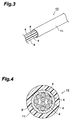
- the coaxial cable 4 comprises a center conductor 5, an insulator 6 covering the periphery of the center conductor 5, and an outer conductor 7 covering the periphery of the insulator 6, which are arranged on the same axis, whereas the periphery of the outer conductor 7 is covered with a sheath (insulator) 8.
- a plurality of coaxial cables 4 are assembled as a multiconductor cable 13 before reaching a pipe 2 constituting the takeout portion 1.
- a plurality of coaxial cables 4 are covered with an outer sheath (insulator) 11 by way of a spirally wound conductor 9 as a grounding shield layer.
- the plurality of coaxial cables 4 contained inside thereof are arranged in parallel close to each other so as to orient in one direction.
- these coaxial cables 4 are drawn out of the outer sheath 11 and introduced (inserted) into the pipe 2 as shown in Fig. 1.
- the pipe 2 is provided with a slit 3a extending in the axial direction of the pipe 2 from an end portion of the pipe 2 so as to be cut partway through the pipe 2 in the axial direction thereof.
- the width of the slit 3a is set ranging from about 1 to 2 times the outside diameter of the coaxial cables 4.
- the length of the slit 3a is appropriately determined according to the number of coaxial cables 4 to be taken out through the slit 3a.
- the terminals of the plurality of coaxial cables 4 are fed to the slit 3a in the order of their alignment at the time of their terminal formation while changing angles from their linear state, so as to be arranged in a row and drawn out from within the pipe 2.
- the plurality of coaxial cables 4 drawn out from the slit 3a in a row are secured to each other and to the pipe 2 with an adhesive 12, for example.
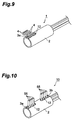
- the draw-out direction of these coaxial cables 4 is appropriately selected according to the terminating direction in which sensors, connectors, and the like are disposed, for example, from a direction forming substantially a right angle with the axis of the pipe 2 as shown in Fig. 1, a direction forming an acute angle with the slit side of the axis of the pipe 2 as shown in Fig. 9, and a direction forming an obtuse angle therewith.
- their respective exposed parts such as the sheaths 8, as the outermost layer, have colors different from each other.
- the pipe 2 is molded from a resin, for example.
- a resin for example.
- it can be formed by injection molding, and its formation flexibility is so high that, for example, a formation which tends to be integrated with sensors, connectors, and the like connected to the terminals can easily be selected.
- thermoplastic materials such as polypropylene, polyethylene terephthalate, and polycarbonate, for example, and the like can be selected as appropriate.
- a material having a hardness lower than that of the sheath 8 is preferable to use as the outermost layer of the coaxial cable 4.
- an epoxy type adhesive or the like is appropriately selected, for example.
- the inside and outside diameters of the pipe 2 are appropriately selected according to the outside diameter and number of the coaxial cables 4 contained in the pipe 2, whether the pipe 2 is secured or not, and the like.
- the outside diameter of the outer sheath 11 is 1.5 mm
- employed as the pipe 2 is a pipe whose outside diameter is not substantially different from that of the multiconductor cable 13 as the assembly before reaching the pipe 2.
- the width of the slit 3a is set ranging from about 1 to 2 times the outside diameter of the coaxial cable 4.
- the width be greater than the outside diameter of each of the aligned coaxial cables 4 by 0.01 mm or more in view of the easiness in operation, and that the width be not greater than about 1.5 times the outside diameter of the coaxial cable 4 taking account of the case where the coaxial cables 4 move within the slit 3a while the coaxial cables 4 deform under the action of forces thereon.
- the outside diameter of the coaxial cable 4 and the width of the slit 3a are close to each other.
- the width of the slit 3a is about 1.1 times the outside diameter of the coaxial cable 4
- the displacement of the coaxial cable 4 in the width direction thereof will be about 10% of the outside diameter of the coaxial cable 4, thereby facilitating the terminating operation for connecting terminals to sensors, connectors, and the like.
- a metal pipe may be employed in place of the resin pipe 2.
- materials such as copper, aluminum, stainless steel, and the like, for example, are selected as appropriate.
- stainless steel which is hard to yield rust and is suitable as the material for medical instruments.
- the above-mentioned adhesive 12 can be used, for example.
- the coated cable 15 comprises a conductor 17 composed of a strand of a plurality of single wires 16 each made of a copper wire, for example, and a sheath 18 as an insulator covering the periphery of the conductor 17.
- a coaxial cable 19 including a drain wire 23 shown in Fig. 7 may be used.
- an insulator 22 is disposed so as to cover the periphery of an inner conductor 21, the drain wire 23 is disposed outside the insulator 22, the periphery of the drain wire 23 and insulator 22 is integrally covered with a metal deposition film 24 as an outer conductor, and the metal deposition film 24 is covered with an outer sheath (insulator) 25 forming a polygon such as an octagon, for example.
- the coaxial cable 4, the coated cable 15, the coaxial cable 19 including the drain wire 23, and the like are collectively referred to as cable with numeral 55, if necessary, when they are considered generically, whereas they are referred to by their respective names with their corresponding numerals when their kinds are to be specified.
- an ultra-multiconductor cable 26 shown in Fig. 8 may be employed.
- a plurality of the above-mentioned coaxial cables 4 a plurality of coaxial cables 65 having a size identical to that of the coaxial cables 4 but being used for a purpose different from that of the coaxial cables 4, and a plurality of coaxial cables 27 having a size different from that of the coaxial cables 4, 65 are covered with an outer sheath 29 by way of a spirally wound conductor 28.
- the coaxial cables 4, 27, 65 are drawn out from the spirally wound conductor 28 and the outer sheath 29, such that all these coaxial cables, respective parts of the individual cable groups, or at least two selected coaxial cables are introduced into the pipe 2, arranged in a row in the slit 3a, and drawn out from within the pipe 2.
- the configuration of multiconductor cables such as ultra-multiconductor cables is not limited to that mentioned above.
- a configuration containing a plurality of kinds of cables whose modes are different from each other, such as coaxial cables and coated cables may be employed.
- all these cables e.g., all of the coaxial cables and coated cables that are contained
- respective parts of the individual kinds, or at least two selected cables are introduced into the pipe 2, arranged in a row in the slit 3a, and drawn out from within the pipe 2.
- a complex mode of assembly having ultra-multiconductor cables such as those shown in Fig. 8 and an assembly bundled with the annular band 14 such as that shown in Fig. 5, for example.
- all the cables, respective parts of cables in the individual modes of assembly, or at least two selected cables are introduced into the pipe, arranged in a row in the slit 3a, and drawn out from within the pipe 2.
- the complex mode of assembly is not limited to this one, but the same kind of assemblies or three or more kinds of assemblies may be combined as well.
- Fig. 10 is a perspective view showing a second embodiment of the multiconductor cable in accordance with the present invention.
- the cable takeout portion 10 in the second embodiment differs from that of the first embodiment in that a slit 3b different from the slit 3a is also formed at a pipe end portion on the side opposite from the slit 3a, whereas a predetermined number of cables 55 are also arranged in a row in this slit 3b, drawn out therefrom while being shaped into a bent form, and secured to the pipe with the adhesive 12 or the like, for example.
- Such a configuration can yield effects similar to those of the first embodiment as a matter of course.
- the retention force for securing the slit width is greater, so that the cables 55 are prevented from being damaged, and the reliability of the cables 55 is improved.
- Such a configuration is particularly effective in the case where the number of cables 55 aligning in the slit is large.
- Fig. 11 is a perspective view showing a third embodiment of the multiconductor cable in accordance with the present invention.
- the cable takeout portion 20 in the third embodiment differs from that of the first embodiment in that a slit 3c different from the slit 3a is formed at a predetermined position in the circumferential direction of the pipe 2, whereas a predetermined number of cables 55 are also arranged in a row in this slit 3c, drawn out therefrom while being shaped into a bent form, and secured to the pipe 2 with the adhesive 12 or the like, for example.
- positions where these slits 3a, 3c are formed are appropriately selected according to terminating directions in which sensors, connectors, and the like are disposed, for example.
- Various positions such as those separated from each other by 180° about the axis of the pipe 2 (positions opposite to each other by 180° ) as shown in Fig. 11, those separated from each other by 90° , and the like may be selected as appropriate.
- Such a configuration can yield effects similar to those of the first embodiment as a matter of course.
- a plurality of cables 55 are aligned and shaped into bent forms in a plurality of directions in the same pipe 2, the range of application can be widened at a lower cost, while a greater number of cables 55 can be terminated.
- Fig. 12 is a perspective view showing a fourth embodiment of the multiconductor cable in accordance with the present invention.
- the cable takeout portion 30 in the fourth embodiment differs from that of the first embodiment in that the pipe 2 is provided with a flat surface 2a extending in the axial direction of the pipe 2 on the external surface, whereas the flat surface 2a is secured to a flat surface 31 such as a wall face within an instrument, a substrate, or the like, for example.
- Such a configuration can yield effects similar to those of the first embodiment as a matter of course.
- the flat surface 2a of the pipe 2 makes it easier to mount the pipe 2 without rotating it, thus improving the mountability, thereby cutting down the cost of manufacture.
- the configuration of the fourth embodiment can be combined with those of the second and third embodiments as a matter of course.
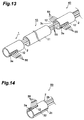
- Fig. 13 is a perspective view showing a fifth embodiment of the multiconductor cable in accordance with the present invention.
- the cable takeout portion 40 in the fifth embodiment differs from that of the first embodiment in that the takeout portion is arranged as a branch for the midsection of the plurality of cables 55 arranged in parallel. While the takeout portion 40 arranged for the midsection of the cables 55 has a configuration similar to that of the takeout portion 20 of the third embodiment, for example, a plurality of cables 55 other than those shaped into a bent form in the takeout portion 40 so as to be drawn out of the pipe 2 are passed through the pipe 2 of the takeout portion 40 so as to be drawn out from an open end thereof.
- the takeout portion 1 of the first embodiment On the terminal side of the plurality of cables 55 drawn out through the pipe 2 of the takeout portion 40, the takeout portion 1 of the first embodiment, for example, is employed.
- the configuration of the multiconductor cable 13 of the first embodiment explained with reference to Figs. 3 and 4, for example, is employed so as to protect these cables 55 and arrange them in parallel close to each other so that they orient in one direction.
- the takeout portion 40 for the midsection of the plurality of cables 55 may be any of the first, second, and fourth embodiments as well, whereas the takeout portion employed on the terminal side may be any of the second to fourth embodiments as well.
- the annular band 14 of the first embodiment explained with reference to Fig. 5 may be used as well.
- Such a configuration can yield effects similar to those of the first embodiment as a matter of course.
- it is also applicable to a mode in which the takeout portion 40 arranged for the midsection of the plurality of cables 55 branches out a part of the plurality of cables 55 partway, whereby its range of application is widened. Not only a plurality of cables but also a single cable may be passed through the pipe 2 of the takeout portion 40 so as to be drawn out from an open end thereof.
- Fig. 14 is a perspective view showing a sixth embodiment of the multiconductor cable in accordance with the present invention.
- the takeout portion 50 in the sixth embodiment differs from that of the first embodiment in that the pipe 2 is divided along the axis thereof into pipe parts 2b, 2c, which are used as being combined together at a predetermined position of a plurality of cables 55 so as to hold the cables 55 therebetween.
- These divided pipe parts 2b, 2c are secured to each other with an adhesive 32 or the like, so as to be integrated together.
- Such a configuration can yield effects similar to those of the first embodiment as a matter of course.
- the pipe 2 is arranged so as to constitute a branch for a midsection of a plurality of cables 55 as in the fifth embodiment in particular, then an operation of introducing the terminals of the plurality of cables 55 into the pipe 2 and moving the pipe 2 toward the midsection of the plurality of cables 55 is unnecessary, whereby the workability improves.
- the chance of the cables 55 and the pipe 2 coming into contact with each other is reduced, so that the cables 55 are prevented from being damaged, whereby the reliability of the cables 55 is improved.
- the divided pipe parts 2b, 2c may be joined to each other by soldering, for example.
- the configuration of the sixth embodiment can be combined with those of the second to fifth embodiments as a matter of course.
- the pipe 2 may be divided into not only two parts but also three or more parts. Its mode of division is not limited to the one depicted as long as the divided parts can be combined together so as to hold the cables 55 therein.
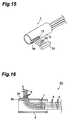
- Fig. 15 is a perspective view showing a seventh embodiment of the multiconductor cable in accordance with the present invention.
- the takeout portion in the seventh embodiment has a configuration similar to the takeout portion 1 in the first embodiment but differs therefrom in that the terminals of a plurality of cables 55 which are bent at the takeout portion 1, arranged in a row, and taken out therefrom are provided with a collective connector 33 for connecting the terminals of these cables 55 in a row.
- Such a configuration can yield effects similar to those of the first embodiment as a matter of course.
- attachment of the connector 33 is quite easy, and the function as the cable takeout portion 1 is fully exhibited.
- the configuration of the seventh embodiment can be combined with those of the second to sixth embodiments as a matter of course.
- Fig. 16 is a vertical sectional view showing an eighth embodiment of the multiconductor cable in accordance with the present invention.
- the cable takeout portion 60 in the eighth embodiment differs from that of the first embodiment in that the cables employed in the takeout portion are coaxial cables 4 stripped of their sheath 8 so as to expose outer conductors 7.
- these outer conductors 7 are arranged in a row in the slit 3a of the pipe 2, shaped into a bent form, and drawn out from within the pipe 2.
- the pipe 2 is made of a solderable electrically conductive material such as a metal, for example, it is possible to employ a configuration in which a plurality of outer conductors 7 drawn out from within the pipe 2 are joined to the pipe 2 by way of solder 34, as shown in Fig. 16, so as to be conducted to each other via the pipe 2.
- the metal material for constituting the pipe 2 copper or aluminum, which can easily be soldered, is preferably used.
- stainless steel is employed as the metal material for constituting the pipe 2, it is preferred that the surface thereof be plated with nickel or gold so as to facilitate soldering.
- the pipe 2 is a resin
- Such a configuration can also yield effects similar to those of the first embodiment as a matter of course.
- the eighth embodiment is in such a state that, as shown in Fig. 16, the outer conductors 7 on the terminal side from the takeout portion 60 are removed so as to expose insulators 6, and these insulators 6 on the terminal side are removed so as to expose center conductors 5, thus making it easier to connect them to sensors, connectors, and the like as termination.
- the coaxial cable 19 including the drain wire 23 of the first embodiment explained with reference to Fig. 7 can be stripped of the sheath 25 to expose the outer conductor (metal deposition film) 24 so as to be used as the cable shaped into a bent form in the takeout portion 60.
- the configuration of the eighth embodiment can be combined with those of the second to seventh embodiments as a matter of course.
- Fig. 17 is a vertical sectional view showing a ninth embodiment of the multiconductor cable in accordance with the present invention. While the takeout portion 70 of the ninth embodiment has a partly limited configuration of the takeout portion 60 of the eighth embodiment, a new configuration is added thereto, so as to yield an improved functionality.
- the configuration of the takeout portion 60 of the eighth embodiment is partly limited in the takeout portion 70 of the ninth embodiment.
- the pipe 2 is constituted by a solderable electrically conductive material such as a metal, for example, outer conductors 7 aligned by the slit 3a and drawn out from within the pipe 2 are joined to the pipe 2 by way of solder 34 so as to be conducted to each other via the pipe 2, and a plurality of coaxial cables 4 before reaching the pipe 2 are assembled in the form of a multiconductor cable 13 comprising a spirally wound conductor 9 as a grounding shield layer for containing these coaxial cables 4.
- a new configuration is added to the configuration of the takeout portion 60 in the eighth embodiment.
- the spirally wound conductor 9 is drawn out of the outer sheath 11, so as to be joined to the pipe 2 by way of solder 35.
- Their joining position may be either on the inner periphery side or outer periphery side of the pipe as indicated by solid lines and phantom lines, respectively, in Fig. 17.
- Such a configuration can also yield effects similar to those of the eighth embodiment as a matter of course.
- the spirally wound conductor 9 containing the coaxial cables 4 is electrically connected to the pipe 2, a plurality of outer conductors 7 drawn out from within the pipe 2 by way of the slit 3a are conducted to the spirally wound conductor 9 via the pipe 2.
- the spirally wound conductor 9 joined to the pipe 2 enhances the retention strength of the pipe 2, thus improving the reliability of the pipe 2 when external forces act thereon.
- the multiconductor cable 13 is employed as a mode of assembly before reaching the pipe 2 so as to draw out outer conductors 7 from inside the spirally wound conductor 9 of the multiconductor cable 13 containing them, arrange them in a row in the slit 3a of the pipe 2, and yield a bent form in Fig. 17, those not contained inside the spirally wound conductor 9 may also be arranged in a row in the slit 3a so as to yield the bent form. Namely, it will be sufficient if at least a part of those arranged in a row in the slit 3a so as to yield a bent form are contained inside the spirally wound conductor 9 before reaching the pipe 2 while the spirally wound conductor 9 containing at least a part thereof is electrically connected to the pipe 2.
- the pipe 2 may be a resin pipe.
- an adhesive for example, may be used in place of the solder 34, 35.
- the pipe 2 is an annular pipe in the above-mentioned embodiments, it may be a square pipe.
- the pipe 2 is not limited to the straight tube (linear pipe), but may be a tube partly or wholly curved according to the draw-out direction of the aligned cables.
- takeout portions 1, 10, 20 to 60, 70 are applied to medical instruments such as an endoscope, electronic instruments such as a low-file notebook PC, and the like in the above-mentioned embodiments since their functions are fully exhibited therein, they are also applicable to others as a matter of course. In particular, they are effective when applied to the case where a plurality of cables are arranged in a narrow space.
- the coaxial cable 4, the coated cable 5, the coaxial cable 4 stripped of the sheath 8 to expose the outer conductor 7, and the coaxial cable 19 including the drain wire 23 stripped of the sheath 25 to expose the outer conductor 24 are subjected to aligning and shaping into a bent form in the above-mentioned embodiments, without being restricted thereto, those having at least a conductor and an insulator covering the periphery of the conductor may be employed for this purpose.
Landscapes
- Insulated Conductors (AREA)
- Cable Accessories (AREA)
- Supports For Pipes And Cables (AREA)
- Endoscopes (AREA)
Abstract
Description
Claims (16)
- A multiconductor cable in which a plurality of cables, each having at least a conductor and an insulator covering a periphery thereof, are aligned at a predetermined part thereof by an alignment member,wherein said alignment member comprising a pipe in which said plurality of cables are inserted, with a slit extending in an axial direction thereof and having a width ranging from about 1 to 2 times the outside diameters of all of said cables, anda predetermined number of cables among said plurality of cables being drawn out from within said pipe and secured while being aligned in said slit in the axial direction of said pipe.
- A multiconductor cable according to claim 1, wherein each said cable is a coated cable in which said conductor is covered with said insulator.
- A multiconductor cable according to claim 1, wherein each said cable is a coaxial cable comprising a center conductor, an insulator covering a periphery of said center conductor, and an outer conductor covering a periphery of said insulator.
- A multiconductor cable according to claim 3, wherein each said cable is a coaxial cable further comprising a sheath covering a periphery of said outer conductor.
- A multiconductor cable according to claim 1, wherein said slit extends from one end portion of said pipe to an intermediate portion of said pipe.
- A multiconductor cable according to claim 5, wherein said pipe has at least one set of said slit, each set of said slit being constituted by two slits extending on a line from both ends of said pipe toward a center of said pipe, respectively.
- A multiconductor cable according to claim 1, wherein said pipe has a plurality of said slits in a circumferential direction thereof.
- A multiconductor cable according to claim 1, wherein the external surface of said pipe has a flat surface.
- A multiconductor cable according to claim 1, wherein said pipe is disposed at the midsection of at least one cable among said plurality of cables.
- A multiconductor cable according to claim 1, wherein said pipe is formed such that a periphery thereof is constituted by a combination of two or more constituent members at any position in the axial direction of said pipe.
- A multiconductor cable according to claim 1, wherein a predetermined number of cables drawn out from said pipe are provided with a collective connector for securing and electrically connecting a terminal portion thereof.
- A multiconductor cable according to claim 3, wherein a plurality of cables and each including said outer conductor are drawn out from said slit, the outer conductors of thus drawn-out cables being joined to each other by way of an electrically conductive bonding layer and secured to said pipe.
- A multiconductor cable according to claim 12, wherein said pipe is made of a solderable electrically conductive material, and wherein solder is used as said bonding layer.
- A multiconductor cable according to claim 13, wherein at least a part of said plurality of cables is contained in a grounded conductor tube, said conductor tube and said pipe being electrically connected to each other.
- An alignment member for aligning a plurality of cables, each having at least a conductor and an insulator covering a periphery thereof, at a predetermined part of said cables;said alignment member having a pipe-like structure in which said plurality of cables are inserted, with a slit extending in an axial direction thereof and having a width ranging from about 1 to 2 times the outside diameters of all of said cables, said alignment member being capable of causing a predetermined number of cables among said plurality of cables to be drawn out from within said pipe and secured while being aligned in said slit in the axial direction of said pipe.
- A method of aligning a multiconductor cable in which a plurality of cables, each having at least a conductor and an insulator covering a periphery thereof, are aligned by an alignment member at a predetermined part of said cables;said method comprising the steps of:inserting said plurality of cables into a pipe-like alignment member formed with a slit extending in an axial direction thereof and having a width ranging from about 1 to 2 times the outside diameters of all of said cables;drawing out a predetermined number of cables among said plurality of cables from within said alignment member;aligning cables thus drawn out in said slit in the axial direction of said alignment member; andsecuring cables thus aligned.
Applications Claiming Priority (2)
| Application Number | Priority Date | Filing Date | Title |
|---|---|---|---|
| JP30436599 | 1999-10-26 | ||
| JP30436599A JP3262165B2 (en) | 1999-10-26 | 1999-10-26 | Wire alignment part |
Publications (3)
| Publication Number | Publication Date |
|---|---|
| EP1096509A2 true EP1096509A2 (en) | 2001-05-02 |
| EP1096509A3 EP1096509A3 (en) | 2002-04-24 |
| EP1096509B1 EP1096509B1 (en) | 2005-05-18 |
Family
ID=17932155
Family Applications (1)
| Application Number | Title | Priority Date | Filing Date |
|---|---|---|---|
| EP00301992A Expired - Lifetime EP1096509B1 (en) | 1999-10-26 | 2000-03-10 | Multiconductor cable |
Country Status (6)
| Country | Link |
|---|---|
| US (1) | US6288337B1 (en) |
| EP (1) | EP1096509B1 (en) |
| JP (1) | JP3262165B2 (en) |
| KR (1) | KR20010051157A (en) |
| DE (1) | DE60020200D1 (en) |
| TW (1) | TW480498B (en) |
Families Citing this family (18)
| Publication number | Priority date | Publication date | Assignee | Title |
|---|---|---|---|---|
| US6712486B1 (en) * | 1999-10-19 | 2004-03-30 | Permlight Products, Inc. | Mounting arrangement for light emitting diodes |
| US6960722B2 (en) | 2003-03-04 | 2005-11-01 | Federal-Mogul World Wide, Inc. | Multi-branch junction overwrap |
| USD512025S1 (en) | 2004-03-04 | 2005-11-29 | Federal-Mogul World Wide, Inc. | Double tube |
| CN101132995B (en) * | 2005-03-08 | 2011-02-02 | 旭硝子株式会社 | Structural member made of platinum or platinum alloy and glass manufacturing device using same |
| USD573101S1 (en) * | 2005-08-29 | 2008-07-15 | Creative Technology Ltd | Cable set |
| JP4764190B2 (en) * | 2006-01-31 | 2011-08-31 | 株式会社オートネットワーク技術研究所 | Shield conductive path |
| JP4910418B2 (en) * | 2006-02-22 | 2012-04-04 | 住友電気工業株式会社 | Manufacturing method of multi-core cable |
| USD585383S1 (en) * | 2006-05-15 | 2009-01-27 | Moroso Performance Products, Inc. | Spark plug wire |
| USD588996S1 (en) * | 2007-07-13 | 2009-03-24 | Julius Blum Gmbh | Electrical connector |
| USD647862S1 (en) | 2008-12-29 | 2011-11-01 | Moroso Performance Products, Inc. | Spark plug wire |
| TW201401300A (en) | 2012-06-26 | 2014-01-01 | Sumitomo Electric Industries | Multi-core cable |
| JP2014022219A (en) * | 2012-07-19 | 2014-02-03 | Yazaki Corp | Wire harness |
| CN104869883B (en) | 2012-10-23 | 2018-07-27 | 波士顿科学国际有限公司 | Signal transmission components used with medical devices |
| USD745851S1 (en) * | 2013-07-10 | 2015-12-22 | Paracable, Inc. | Electronics cable |
| JP6551733B2 (en) * | 2015-05-28 | 2019-07-31 | 日立金属株式会社 | Multi-core shielded cable and method of branching the same |
| JP2017056541A (en) * | 2015-09-20 | 2017-03-23 | 株式会社潤工社 | Filament holding mechanism |
| US11067757B2 (en) * | 2019-03-04 | 2021-07-20 | Tyonek Manufacturing Group, LLC | Optical wire transition adapter |
| US20260097721A1 (en) * | 2024-10-07 | 2026-04-09 | Arvinmeritor Technology, Llc | Support member for routing a fluid or electrical line in a structural member |
Family Cites Families (6)
| Publication number | Priority date | Publication date | Assignee | Title |
|---|---|---|---|---|
| US3510827A (en) * | 1967-11-14 | 1970-05-05 | Etc Inc | T-tap connectors |
| US3761603A (en) * | 1972-11-14 | 1973-09-25 | Amp Inc | Wiring raceway |
| US5524338A (en) * | 1991-10-22 | 1996-06-11 | Pi Medical Corporation | Method of making implantable microelectrode |
| US5201903A (en) * | 1991-10-22 | 1993-04-13 | Pi (Medical) Corporation | Method of making a miniature multi-conductor electrical cable |
| JPH0546607U (en) * | 1991-12-04 | 1993-06-22 | 富士重工業株式会社 | Wire harness intermediate output device |
| US5352855A (en) * | 1993-03-23 | 1994-10-04 | Cumming Electronics Company, Inc. | Junction clamp for wiring harness |
-
1999
- 1999-10-26 JP JP30436599A patent/JP3262165B2/en not_active Expired - Fee Related
-
2000
- 2000-02-29 US US09/516,206 patent/US6288337B1/en not_active Expired - Fee Related
- 2000-03-10 EP EP00301992A patent/EP1096509B1/en not_active Expired - Lifetime
- 2000-03-10 DE DE60020200T patent/DE60020200D1/en not_active Expired - Lifetime
- 2000-10-20 KR KR1020000061815A patent/KR20010051157A/en not_active Withdrawn
- 2000-10-23 TW TW089122239A patent/TW480498B/en not_active IP Right Cessation
Also Published As
| Publication number | Publication date |
|---|---|
| JP3262165B2 (en) | 2002-03-04 |
| EP1096509A3 (en) | 2002-04-24 |
| TW480498B (en) | 2002-03-21 |
| KR20010051157A (en) | 2001-06-25 |
| DE60020200D1 (en) | 2005-06-23 |
| US6288337B1 (en) | 2001-09-11 |
| EP1096509B1 (en) | 2005-05-18 |
| JP2001126542A (en) | 2001-05-11 |
Similar Documents
| Publication | Publication Date | Title |
|---|---|---|
| US6288337B1 (en) | Multiconductor cable | |
| KR101001804B1 (en) | Coaxial cable connection structure, coaxial cable harness used for it, and portable terminal equipment | |
| US20020050386A1 (en) | Electrical cable terminal part structure and treatment method | |
| US7271340B2 (en) | Flexible interconnect cable with insulated shield and method of manufacturing | |
| US7534138B1 (en) | Electrical cable shielding terminal | |
| US8801461B2 (en) | Stepped termination block | |
| CN101507051A (en) | Grounding structure and grounding method for shield wire | |
| JP2010211937A (en) | Transmission cable with connector | |
| US20170200533A1 (en) | Nested shielded ribbon cables | |
| US8704088B2 (en) | Electrical connecting cable | |
| US10566709B2 (en) | Electrical connector having an electrical device mounted to a flexible carrier | |
| US6281856B1 (en) | Method for making antenna of coaxial cable and the antenna so made | |
| JP2013026181A (en) | Small-diameter cable harness | |
| JP2010040214A (en) | Grounding member and grounding method of collective cable, and collective cable assembly | |
| JP2011233451A (en) | Cable connector for signal transmission, cable for signal transmission with connector using the same, and electric connection part of cable for signal transmission | |
| JP5325698B2 (en) | Wire connection unit | |
| JP2005310563A (en) | Wiring member and manufacturing method thereof | |
| US20020139561A1 (en) | Flexible interconnect cable with ribbonized ends | |
| US10903159B2 (en) | Electrical cable | |
| US20240404732A1 (en) | Multicore cable | |
| US20240079798A1 (en) | Splice Terminal and Method for Making a Splice Arrangement | |
| JP7581891B2 (en) | Wire Harness | |
| JPH08201880A (en) | Electrical connection | |
| CN101325101B (en) | Cable combination | |
| JP3006381B2 (en) | Drain circuit structure of shielded wire |
Legal Events
| Date | Code | Title | Description |
|---|---|---|---|
| PUAI | Public reference made under article 153(3) epc to a published international application that has entered the european phase |
Free format text: ORIGINAL CODE: 0009012 |
|
| AK | Designated contracting states |
Kind code of ref document: A2 Designated state(s): AT BE CH CY DE DK ES FI FR GB GR IE IT LI LU MC NL PT SE Kind code of ref document: A2 Designated state(s): DE FR GB IT |
|
| AX | Request for extension of the european patent |
Free format text: AL;LT;LV;MK;RO;SI |
|
| PUAL | Search report despatched |
Free format text: ORIGINAL CODE: 0009013 |
|
| AK | Designated contracting states |
Kind code of ref document: A3 Designated state(s): AT BE CH CY DE DK ES FI FR GB GR IE IT LI LU MC NL PT SE |
|
| AX | Request for extension of the european patent |
Free format text: AL;LT;LV;MK;RO;SI |
|
| 17P | Request for examination filed |
Effective date: 20020816 |
|
| AKX | Designation fees paid |
Free format text: DE FR GB IT |
|
| 17Q | First examination report despatched |
Effective date: 20040625 |
|
| GRAP | Despatch of communication of intention to grant a patent |
Free format text: ORIGINAL CODE: EPIDOSNIGR1 |
|
| GRAS | Grant fee paid |
Free format text: ORIGINAL CODE: EPIDOSNIGR3 |
|
| GRAA | (expected) grant |
Free format text: ORIGINAL CODE: 0009210 |
|
| RIN1 | Information on inventor provided before grant (corrected) |
Inventor name: SATO, KAZUHIRO,KANTOH W. SUMITOMO ELEC. IND. LTD Inventor name: KIKUCHI, HIDEO,KANTOH W. SUMITOMO ELEC. IND. LTD. |
|
| AK | Designated contracting states |
Kind code of ref document: B1 Designated state(s): DE FR GB IT |
|
| REG | Reference to a national code |
Ref country code: GB Ref legal event code: FG4D |
|
| REG | Reference to a national code |
Ref country code: IE Ref legal event code: FG4D |
|
| REF | Corresponds to: |
Ref document number: 60020200 Country of ref document: DE Date of ref document: 20050623 Kind code of ref document: P |
|
| PG25 | Lapsed in a contracting state [announced via postgrant information from national office to epo] |
Ref country code: DE Free format text: LAPSE BECAUSE OF FAILURE TO SUBMIT A TRANSLATION OF THE DESCRIPTION OR TO PAY THE FEE WITHIN THE PRESCRIBED TIME-LIMIT Effective date: 20050819 |
|
| PG25 | Lapsed in a contracting state [announced via postgrant information from national office to epo] |
Ref country code: GB Free format text: LAPSE BECAUSE OF NON-PAYMENT OF DUE FEES Effective date: 20060310 |
|
| ET | Fr: translation filed | ||
| PLBE | No opposition filed within time limit |
Free format text: ORIGINAL CODE: 0009261 |
|
| STAA | Information on the status of an ep patent application or granted ep patent |
Free format text: STATUS: NO OPPOSITION FILED WITHIN TIME LIMIT |
|
| 26N | No opposition filed |
Effective date: 20060221 |
|
| GBPC | Gb: european patent ceased through non-payment of renewal fee |
Effective date: 20060310 |
|
| PGFP | Annual fee paid to national office [announced via postgrant information from national office to epo] |
Ref country code: FR Payment date: 20100324 Year of fee payment: 11 Ref country code: IT Payment date: 20100320 Year of fee payment: 11 |
|
| REG | Reference to a national code |
Ref country code: FR Ref legal event code: ST Effective date: 20111130 |
|
| PG25 | Lapsed in a contracting state [announced via postgrant information from national office to epo] |
Ref country code: FR Free format text: LAPSE BECAUSE OF NON-PAYMENT OF DUE FEES Effective date: 20110331 |
|
| PG25 | Lapsed in a contracting state [announced via postgrant information from national office to epo] |
Ref country code: IT Free format text: LAPSE BECAUSE OF NON-PAYMENT OF DUE FEES Effective date: 20110310 |