EP1096507A1 - An absorbing rod, an apparatus for inserting the absorbing rod, a cask, and a method of storing spent fuel assemblies - Google Patents
An absorbing rod, an apparatus for inserting the absorbing rod, a cask, and a method of storing spent fuel assemblies Download PDFInfo
- Publication number
- EP1096507A1 EP1096507A1 EP00122355A EP00122355A EP1096507A1 EP 1096507 A1 EP1096507 A1 EP 1096507A1 EP 00122355 A EP00122355 A EP 00122355A EP 00122355 A EP00122355 A EP 00122355A EP 1096507 A1 EP1096507 A1 EP 1096507A1
- Authority
- EP
- European Patent Office
- Prior art keywords
- absorbing
- spent fuel
- fuel assemblies
- pwr
- control rod
- Prior art date
- Legal status (The legal status is an assumption and is not a legal conclusion. Google has not performed a legal analysis and makes no representation as to the accuracy of the status listed.)
- Granted
Links
- 238000000429 assembly Methods 0.000 title claims abstract description 106
- 230000000712 assembly Effects 0.000 title claims abstract description 106
- 239000002915 spent fuel radioactive waste Substances 0.000 title claims description 112
- 238000000034 method Methods 0.000 title claims description 13
- 230000009257 reactivity Effects 0.000 claims abstract description 14
- 229910052782 aluminium Inorganic materials 0.000 claims description 42
- XAGFODPZIPBFFR-UHFFFAOYSA-N aluminium Chemical compound [Al] XAGFODPZIPBFFR-UHFFFAOYSA-N 0.000 claims description 32
- 239000000843 powder Substances 0.000 claims description 27
- 229910000838 Al alloy Inorganic materials 0.000 claims description 22
- ZOXJGFHDIHLPTG-UHFFFAOYSA-N Boron Chemical compound [B] ZOXJGFHDIHLPTG-UHFFFAOYSA-N 0.000 claims description 20
- 229910052796 boron Inorganic materials 0.000 claims description 19
- 239000002131 composite material Substances 0.000 claims description 14
- 150000001639 boron compounds Chemical class 0.000 claims description 13
- 238000001514 detection method Methods 0.000 claims description 11
- 150000001875 compounds Chemical class 0.000 claims description 5
- 239000000446 fuel Substances 0.000 abstract description 57
- 239000000463 material Substances 0.000 description 27
- 239000002245 particle Substances 0.000 description 19
- 210000004027 cell Anatomy 0.000 description 13
- 239000000725 suspension Substances 0.000 description 12
- XLYOFNOQVPJJNP-UHFFFAOYSA-N water Substances O XLYOFNOQVPJJNP-UHFFFAOYSA-N 0.000 description 12
- 239000000498 cooling water Substances 0.000 description 10
- 239000011159 matrix material Substances 0.000 description 10
- -1 aluminum compound Chemical class 0.000 description 9
- 238000010586 diagram Methods 0.000 description 9
- 238000003780 insertion Methods 0.000 description 9
- 230000037431 insertion Effects 0.000 description 9
- 238000001816 cooling Methods 0.000 description 8
- 239000013307 optical fiber Substances 0.000 description 8
- 229910052770 Uranium Inorganic materials 0.000 description 6
- JFALSRSLKYAFGM-UHFFFAOYSA-N uranium(0) Chemical compound [U] JFALSRSLKYAFGM-UHFFFAOYSA-N 0.000 description 6
- 230000003247 decreasing effect Effects 0.000 description 5
- 238000005551 mechanical alloying Methods 0.000 description 5
- 239000011347 resin Substances 0.000 description 5
- 229920005989 resin Polymers 0.000 description 5
- 238000000889 atomisation Methods 0.000 description 4
- 150000001247 metal acetylides Chemical class 0.000 description 4
- 239000008188 pellet Substances 0.000 description 4
- 238000003860 storage Methods 0.000 description 4
- 229910001093 Zr alloy Inorganic materials 0.000 description 3
- 239000011358 absorbing material Substances 0.000 description 3
- 210000000078 claw Anatomy 0.000 description 3
- 238000003384 imaging method Methods 0.000 description 3
- 150000002823 nitrates Chemical class 0.000 description 3
- 230000008569 process Effects 0.000 description 3
- CPLXHLVBOLITMK-UHFFFAOYSA-N Magnesium oxide Chemical compound [Mg]=O CPLXHLVBOLITMK-UHFFFAOYSA-N 0.000 description 2
- VYPSYNLAJGMNEJ-UHFFFAOYSA-N Silicium dioxide Chemical compound O=[Si]=O VYPSYNLAJGMNEJ-UHFFFAOYSA-N 0.000 description 2
- GWEVSGVZZGPLCZ-UHFFFAOYSA-N Titan oxide Chemical compound O=[Ti]=O GWEVSGVZZGPLCZ-UHFFFAOYSA-N 0.000 description 2
- MCMNRKCIXSYSNV-UHFFFAOYSA-N Zirconium dioxide Chemical compound O=[Zr]=O MCMNRKCIXSYSNV-UHFFFAOYSA-N 0.000 description 2
- 230000004308 accommodation Effects 0.000 description 2
- 230000015572 biosynthetic process Effects 0.000 description 2
- 230000007423 decrease Effects 0.000 description 2
- QDOXWKRWXJOMAK-UHFFFAOYSA-N dichromium trioxide Chemical compound O=[Cr]O[Cr]=O QDOXWKRWXJOMAK-UHFFFAOYSA-N 0.000 description 2
- 238000004519 manufacturing process Methods 0.000 description 2
- 238000002156 mixing Methods 0.000 description 2
- 230000003287 optical effect Effects 0.000 description 2
- 230000003647 oxidation Effects 0.000 description 2
- 238000007254 oxidation reaction Methods 0.000 description 2
- 238000012545 processing Methods 0.000 description 2
- 238000007712 rapid solidification Methods 0.000 description 2
- 238000005096 rolling process Methods 0.000 description 2
- 230000035939 shock Effects 0.000 description 2
- 239000010935 stainless steel Substances 0.000 description 2
- 229910001220 stainless steel Inorganic materials 0.000 description 2
- 238000005728 strengthening Methods 0.000 description 2
- 229910018084 Al-Fe Inorganic materials 0.000 description 1
- 229910018134 Al-Mg Inorganic materials 0.000 description 1
- 229910018131 Al-Mn Inorganic materials 0.000 description 1
- 229910018182 Al—Cu Inorganic materials 0.000 description 1
- 229910018192 Al—Fe Inorganic materials 0.000 description 1
- 229910018467 Al—Mg Inorganic materials 0.000 description 1
- 229910018464 Al—Mg—Si Inorganic materials 0.000 description 1
- 229910018461 Al—Mn Inorganic materials 0.000 description 1
- 229910018571 Al—Zn—Mg Inorganic materials 0.000 description 1
- 229910000975 Carbon steel Inorganic materials 0.000 description 1
- RYGMFSIKBFXOCR-UHFFFAOYSA-N Copper Chemical compound [Cu] RYGMFSIKBFXOCR-UHFFFAOYSA-N 0.000 description 1
- 229910052693 Europium Inorganic materials 0.000 description 1
- 229910052688 Gadolinium Inorganic materials 0.000 description 1
- 229910052772 Samarium Inorganic materials 0.000 description 1
- 229910052581 Si3N4 Inorganic materials 0.000 description 1
- 229910007935 ZrBr2 Inorganic materials 0.000 description 1
- WZECUPJJEIXUKY-UHFFFAOYSA-N [O-2].[O-2].[O-2].[U+6] Chemical compound [O-2].[O-2].[O-2].[U+6] WZECUPJJEIXUKY-UHFFFAOYSA-N 0.000 description 1
- 239000006096 absorbing agent Substances 0.000 description 1
- 238000010521 absorption reaction Methods 0.000 description 1
- PNEYBMLMFCGWSK-UHFFFAOYSA-N aluminium oxide Inorganic materials [O-2].[O-2].[O-2].[Al+3].[Al+3] PNEYBMLMFCGWSK-UHFFFAOYSA-N 0.000 description 1
- 210000001084 basket cell Anatomy 0.000 description 1
- 238000009835 boiling Methods 0.000 description 1
- 229910052793 cadmium Inorganic materials 0.000 description 1
- 239000010962 carbon steel Substances 0.000 description 1
- 238000006243 chemical reaction Methods 0.000 description 1
- 229910052681 coesite Inorganic materials 0.000 description 1
- 238000010276 construction Methods 0.000 description 1
- 229910052802 copper Inorganic materials 0.000 description 1
- 239000010949 copper Substances 0.000 description 1
- 238000012937 correction Methods 0.000 description 1
- 229910052593 corundum Inorganic materials 0.000 description 1
- 230000008878 coupling Effects 0.000 description 1
- 238000010168 coupling process Methods 0.000 description 1
- 238000005859 coupling reaction Methods 0.000 description 1
- 229910052906 cristobalite Inorganic materials 0.000 description 1
- 230000000694 effects Effects 0.000 description 1
- 238000002474 experimental method Methods 0.000 description 1
- 230000004992 fission Effects 0.000 description 1
- 239000012530 fluid Substances 0.000 description 1
- 230000005251 gamma ray Effects 0.000 description 1
- 238000009689 gas atomisation Methods 0.000 description 1
- 229910052735 hafnium Inorganic materials 0.000 description 1
- 238000010438 heat treatment Methods 0.000 description 1
- 230000006872 improvement Effects 0.000 description 1
- 230000010354 integration Effects 0.000 description 1
- 229910052751 metal Inorganic materials 0.000 description 1
- 239000002184 metal Substances 0.000 description 1
- 239000000203 mixture Substances 0.000 description 1
- 238000012986 modification Methods 0.000 description 1
- 230000004048 modification Effects 0.000 description 1
- 230000000149 penetrating effect Effects 0.000 description 1
- 230000005855 radiation Effects 0.000 description 1
- 239000000941 radioactive substance Substances 0.000 description 1
- 229910052761 rare earth metal Inorganic materials 0.000 description 1
- 238000012958 reprocessing Methods 0.000 description 1
- 239000011359 shock absorbing material Substances 0.000 description 1
- 238000004904 shortening Methods 0.000 description 1
- 239000000377 silicon dioxide Substances 0.000 description 1
- 238000005245 sintering Methods 0.000 description 1
- 229910052682 stishovite Inorganic materials 0.000 description 1
- 229920001187 thermosetting polymer Polymers 0.000 description 1
- 229910052905 tridymite Inorganic materials 0.000 description 1
- 229910000439 uranium oxide Inorganic materials 0.000 description 1
- 239000013585 weight reducing agent Substances 0.000 description 1
- 238000003466 welding Methods 0.000 description 1
- 239000002023 wood Substances 0.000 description 1
- 229910001845 yogo sapphire Inorganic materials 0.000 description 1
- 229910052726 zirconium Inorganic materials 0.000 description 1
Images





Classifications
-
- G—PHYSICS
- G21—NUCLEAR PHYSICS; NUCLEAR ENGINEERING
- G21F—PROTECTION AGAINST X-RADIATION, GAMMA RADIATION, CORPUSCULAR RADIATION OR PARTICLE BOMBARDMENT; TREATING RADIOACTIVELY CONTAMINATED MATERIAL; DECONTAMINATION ARRANGEMENTS THEREFOR
- G21F5/00—Transportable or portable shielded containers
- G21F5/06—Details of, or accessories to, the containers
-
- G—PHYSICS
- G21—NUCLEAR PHYSICS; NUCLEAR ENGINEERING
- G21C—NUCLEAR REACTORS
- G21C19/00—Arrangements for treating, for handling, or for facilitating the handling of, fuel or other materials which are used within the reactor, e.g. within its pressure vessel
- G21C19/40—Arrangements for preventing occurrence of critical conditions, e.g. during storage
-
- G—PHYSICS
- G21—NUCLEAR PHYSICS; NUCLEAR ENGINEERING
- G21F—PROTECTION AGAINST X-RADIATION, GAMMA RADIATION, CORPUSCULAR RADIATION OR PARTICLE BOMBARDMENT; TREATING RADIOACTIVELY CONTAMINATED MATERIAL; DECONTAMINATION ARRANGEMENTS THEREFOR
- G21F5/00—Transportable or portable shielded containers
- G21F5/005—Containers for solid radioactive wastes, e.g. for ultimate disposal
- G21F5/008—Containers for fuel elements
-
- Y—GENERAL TAGGING OF NEW TECHNOLOGICAL DEVELOPMENTS; GENERAL TAGGING OF CROSS-SECTIONAL TECHNOLOGIES SPANNING OVER SEVERAL SECTIONS OF THE IPC; TECHNICAL SUBJECTS COVERED BY FORMER USPC CROSS-REFERENCE ART COLLECTIONS [XRACs] AND DIGESTS
- Y02—TECHNOLOGIES OR APPLICATIONS FOR MITIGATION OR ADAPTATION AGAINST CLIMATE CHANGE
- Y02E—REDUCTION OF GREENHOUSE GAS [GHG] EMISSIONS, RELATED TO ENERGY GENERATION, TRANSMISSION OR DISTRIBUTION
- Y02E30/00—Energy generation of nuclear origin
- Y02E30/30—Nuclear fission reactors
-
- Y—GENERAL TAGGING OF NEW TECHNOLOGICAL DEVELOPMENTS; GENERAL TAGGING OF CROSS-SECTIONAL TECHNOLOGIES SPANNING OVER SEVERAL SECTIONS OF THE IPC; TECHNICAL SUBJECTS COVERED BY FORMER USPC CROSS-REFERENCE ART COLLECTIONS [XRACs] AND DIGESTS
- Y10—TECHNICAL SUBJECTS COVERED BY FORMER USPC
- Y10S—TECHNICAL SUBJECTS COVERED BY FORMER USPC CROSS-REFERENCE ART COLLECTIONS [XRACs] AND DIGESTS
- Y10S376/00—Induced nuclear reactions: processes, systems, and elements
- Y10S376/90—Particular material or material shapes for fission reactors
- Y10S376/901—Fuel
- Y10S376/902—Fuel with external lubricating or absorbing material
Definitions
- the present invention relates to an absorbing rod having a neutron absorbing capability to be inserted into a control rod guide pipe of spent fuel assemblies, an inserting apparatus for inserting the absorbing rod into the control rod guide pipe, a cask for containing, conveying and storing the spent fuel assemblies, and a conveying and storing method of spent fuel assemblies.
- Spent fuels Fuel assemblies consumed and no longer usable in a terminal stage of fuel cycle are called spent fuels.
- Spent fuels contain fission products and other highly radioactive substances, and must be cooled thermally, and hence they are cooled for a specific period in a cooling pit at a nuclear power plant. Then they are transferred into a shielding container called cask, and conveyed and stored at reprocessing plant or storage facility by means of truck or ship.
- a holding element having a lattice section called basket is used.
- Each one of the spent fuel assemblies is put into each of the cells formed as plural storing spaces in the basket, and a proper holding strength to withstand vibration during transportation is assured.
- FIG. 13 is a perspective view of an example of a cask.
- Fig. 14 is art axial direction sectional view of the cask shown in Fig. 13.
- a cask 500 is composed of a shell main body 501, a resin 502 which is a neutron shield provided on the outer circumference of the shell main body 501, its outer tube 503, bottom 504 and lid 505.
- the shell main body 501 and bottom 504 are carbon steel forged parts which are gamma-ray shielding materials.
- the lid 505 is composed of a primary lid 506 and a secondary lid 507 made of stainless steel or the like.
- the shell main body 501 and bottom 504 are bonded by butt welding.
- the primary lid 506 and secondary lid 507 are fixed to the shell main body 501 by means of stainless steel bolts.
- a metal O-ring is interposed between the lid 505 and shell main body 501, and the inside is kept airtight.
- a basket 509 is a bundle structure of 69 square pipes 510 as shown in Fig. 14, and is inserted into a cavity 511 in the shell main body 501.
- the square pipes 510 are made of aluminum alloy mixing neutron absorbing material (boron: B) so that the inserted spent fuel assemblies may not reach the criticality.
- a trunnion 513 (only one is shown) for suspending the cask 500.
- a buffer materials 514 assembling wood or other shock-absorbing materials are provided (only one side is shown).
- Reference numeral 515 is a cell for accommodating the spent fuel assemblies.
- the light-water type reactor is classified into the boiling water reactor (BWR) and pressurized water reactor (PWR).
- This cask 500 is the cask for storing the spent fuel assemblies used in BWR.
- the structure of the fuel assembly for BWR is shown in Fig. 15.
- the fuel assembly for BWR has four channel boxes 601 arranged in lattice, and a cross-shaped control rod 608 is located in the central area, and the reactivity of fuel rods 603 is controlled by the vertical move of the control rod 608.
- the fuel assembly 600 has 8 ⁇ 8 fuel rods 603 arranged in lattice. Each fuel rod 603 is a long bar of about 4 meters. A support lattice 607 is provided for supporting the fuel rod 603. In each fuel rod 603, plural columnar pellets 631 formed by sintering powder of uranium oxide are inserted as fuel into a cylindrical clad pipe 633 composed of zirconium alloy, and held by a spring 632 inserted in the upper part of the clad pipe 633. A handle 610 is used for lifting up and down the fuel assembly 600.
- the spent fuel assembly inserted in the cell 515 in this cask 500 is a fuel assembly for BWR 600 shown in Fig. 15.
- the fuel assembly shown in Fig. 16 is used in PWR.
- control rods 708 are properly distributed among fuel rods 703, and the fuel rods 703 and control rods 708 are arranged in 17 ⁇ 17 lattice form.
- one measuring pipe is disposed in the center, and 24 control rods 708 are distributed.
- Each fuel rod 703 is a long bar of about 4 meters same as the fuel rod 603 for BWR, and hence a support lattice 707 for supporting the fuel rod 703 is provided.
- plural pellets 731 are inserted into a cylindrical clad pipe 733 composed of zirconium alloy, and held by a spring 732 inserted in the upper part of the clad pipe 733. In this cask, 70 units of spent fuel assemblies are contained in the cell.
- Fig. 17 is an axial direction sectional view of the cask for PWR.
- a cavity 811 of a cask 800 for PWR contains a basket 809 forming a cell 815 of rectangular section by alternately combining plates 817 extending in the radial direction.
- Each plate 817 is composed of aluminum alloy mixing B as neutron absorbing material, same as the square pipes 510 for BWR.
- each plate 817 has a through-hole of cooling water passage 816 extending in the axial direction, known as water zone, and when cooling the spent fuel assemblies, each basket cell and this through-hole are filled with water to moderate neutrons, so that the neutrons may be absorbed efficiently by the plates 817 and the resin 802.
- the water filling the cooling water passage 816 is discharged after a specified cooling period, and the passage is dried.
- This cooling water passage 816 is required because the uranium enrichment factor of fuel assembly for PWR is higher than that of the fuel assembly for BWR, the uranium charging amount per fuel assembly is larger, the sectional area of the fuel assembly is wider, and hence the reactivity is higher in the system arranging these assemblies.
- the distance dd shown in Fig. 17 is such a distance that it assures the subcriticality of the spent fuel assembly.
- the distance dd for PWR is required to be longer than the same for BWR.
- the cells 815 are not arranged in lattice but are deviated in position, which is intended to dispose the spent fuel assemblies for PWR, having a wider sectional area as compared with the spent fuel assemblies for BWR, efficiently in the cavity 811.
- the control rods 708 distributed among the fuel rods 703 arranged in lattice are extracted, and the spent fuel assemblies 700 from which the control rods 708 are extracted are inserted and stored in the cells 815 formed by the basket 809 in the cask 800.
- the vacancies left over by the extracted control rods 708 or measuring rod, not shown, in the spent fuel assemblies are dead spaces, and it is desired to utilize these spaces effectively.
- the plates or square pipes for forming the basket for PWR are required to form the cooling water passage 816, and formation of plates or square pipes is more complicated as compared with formation of plates or square pipes for BWR, and it takes much time and labor.
- the sectional area of the spent fuel assemblies for PWR is rectangular and wide, and also the cooling water passage 816 is needed, and hence the accommodation efficiency of the spent fuels in the cask is poor.
- the absorbing rod according to one aspect of this invention has nearly the same shape as the shape of a columnar control rod for PWR. Further, the absorbing rod has the ability to shield the neutrons. Since the absorbing rod has nearly the same shape as the shape of the columnar control rod for PWR, this absorbing rod can be inserted into the control rod guide pipe of spent fuel assemblies or the control rod guide pipe including the measuring pipe.
- the absorbing rod according to another aspect of this invention is made of aluminum composite material or aluminum alloy formed by adding powder of boron or boron compound having a neutron absorbing performance to aluminum or aluminum alloy powder. Since the absorbing rod is made of such material, it does not get damaged by minor shocks during transportation. As a consequence, it is possible to maintain the neutron absorbing ability even during transport. For example, it is much safer and therefore preferable than an absorbing rod having a structure in which boron powder is filled inside a pipe.
- the cask according to still another aspect of this invention comprises an absorbing rod group having nearly the same shape as the shape of a columnar control rod for PWR. Further, the absorbing rod group has the ability to shield the neutrons.
- the spent fuel assemblies is stored in the cask. Accordingly, the number of neutrons radiated from the spent fuel assemblies can be decreased. Further, the spacing between the spent fuel assemblies can be shortened.
- the inserting apparatus comprises a position detection unit which detects the distance between a through-hole group of the guide member and the control rod guide pipe group of the spent fuel assemblies, and their relative positions are adjusted accordingly. Further, the absorbing rod block is lowered so that the through-hole group acts as a guide hole, and the long absorbing rod group can be inserted securely into the control rod guide pipe or the control rod guide pipe including the measuring pipe.
- the conveying and storing method of spent fuel assemblies comprises a step of inserting an absorbing rod group having a nearly same shape as the shape of a columnar control rod for PWR used in reactivity control of core in a reactor, and having a neutron shielding capability, into a control rod guide pipe group including a measuring pipe of spent fuel assemblies for PWR. Further, the spent fuel assemblies for PWR are conveyed and stored in a state in which the absorbing rod group is inserted. Accordingly, the distance between spent fuel assemblies can be shortened.
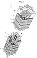
- FIG. 1 is a perspective view showing a general view of a spent fuel assembly for PWR.
- a fuel assembly 1 which is a spent fuel assembly, is formed as a lattice bundling of fuel rods 4, control rod guide pipes 5, and measuring pipes 6, being arranged in a matrix section of 14 ⁇ 14.
- This matrix arrangement is supported by support lattices 7 provided at proper positions in the longitudinal direction of the fuel rods 4, control rod guide pipes 5, and measuring pipes 6.
- the control rod guide pipes 5 and measuring pipes 6 are supported by an upper nozzle 2 and a lower nozzle 3.
- control rod guide pipes 5 and measuring pipes 6 are cylindrical in shape, and held by through-holes between the upper nozzle 2 and lower nozzle 3 provided corresponding to the matrix arrangement positions of the control rod guide pipes 5 and measuring pipes 6.
- control rods having a neutron absorbing capability in the reactor are inserted, and the reactivity of the core is controlled by the number and depth of insertion of control rods.
- the control rod guide pipes 5 are dispersed on the matrix arrangement.
- measuring rods not shown in the drawing are inserted periodically in the reactor for measuring the temperature and radiation dose, and the information for core management is obtained. However, when stored as spent fuel assembly, the control rods inserted in the control rod guide pipes 5 are extracted, and similarly measuring rods are extracted from the measuring pipes 6.
- each absorbing rod 11 having the same columnar shape as the control rods and measuring rods to be inserted in the control rod guide pipes 5 and measuring pipes 6 and having a neutron absorbing capability are newly prepared, and these absorbing rods are inserted into the control rod guide pipes 5 and measuring pipes 6 of the fuel assembly 1.
- One end of each absorbing rod 11 is bonded to an end plate 12 which is a rectangular plate member to be inserted inside from the upper opening of the upper nozzle 2, and the other end is formed in a taper, so as to be inserted easily into the control rod guide pipes 5 and measuring pipes 6.
- the length of the absorbing rod 11 is long enough to envelop the effective length of the fuel.
- the radius of the absorbing rod 11 is less then the inside diameter of the control rod guide pipe 5 and measuring pipe 6, and is preferred to be closer to the inside diameter of the control rod guide pipe 5 and measuring pipe 6 as far as possible, but a certain clearance is required considering the length of about 4 meters.
- Fig. 3 is a plan of the fuel assembly 1 shown in Fig. 2.
- the upper nozzle 2 shown in Fig. 3 corresponds to the matrix arrangement, in which the control rod guide pipes 5 and measuring pipes 6 are disposed.
- the absorbing rod 11 is penetrating through the control rod guide pipe 5 and measuring pipe 6.
- Fig. 4 is a sectional view along line A-A of support lattice 7 of the fuel assembly 1 shown in Fig. 2.
- the support lattice 7 supports the lattice state of 14 ⁇ 14 consisting of fuel rods 4, control rod guide pipes 5 and measuring pipes 6.
- the absorbing rods 11 penetrate through the control rod guide pipes 5 and measuring pipes 6 of the support lattice 7 shown in Fig. 4.
- the end plate 12 shown in Fig. 2 is bonded with the absorbing rod 11 so that the absorbing rod 11 may be held in the state inserted in the control rod guide pipe 5 and measuring pipe 6.
- an absorbing rod block 10 formed by boding plural absorbing rods 11 and end plates 12 a plurality of absorbing rods 11 can be inserted in batch into the control rod guide pipes 5 and measuring pipes 6.
- the absorbing rods 11 instead of bonding the absorbing rods 11 by using end plates 12, the absorbing rods 11 may be individually inserted into the control rod guide pipes 5 and measuring pipes 6.
- Fig. 5 is a front view of the fuel rod 4.
- plural pellets 31 are inserted into a cylindrical clad pipe 33 composed of zirconium alloy, and the pellets 31 are held by a spring 32 inserted in the upper part of the clad pipe 33.
- This fuel pipe 4 is mainly composed of the spent fuel assembly as mentioned above.
- the absorbing rod 11 is composed of aluminum composite material or aluminum alloy formed by adding powder of boron or boron compound having neutron absorbing capability, to the powder of aluminum or aluminum alloy, and it is designed not to reach the criticality from the inside of the spent fuel assembly.
- the following material may preferably used as the aluminum composite material.
- third particles of oxides may be added. Accordingly, mechanical alloying is performed and the strength of the material can be increased.
- powder of aluminum or aluminum alloy as the matrix material, boron or boron compound as the neutron absorber, and third particles as oxides, nitrates, carbides, borides are mixed in the Attriter pan.
- the amount of these third particles should preferably be greater than 0.1 weight percent and less than 30 weight percent. Such an amount is preferable because, if the amount is less than 0.1 weight percent, then there is not much effect on strengthening the material. On the other hand, if the amount is greater than 30 weight percent, then the property of the material to expand decreases. Further, it is preferable that the diameters of the third particles in the aluminum matrix is greater than 0.01 ⁇ m and less than 10 ⁇ m. The material having a diameter smaller than 0.01 ⁇ m is very costly and difficult to acquire. On the other hand, the material having a diameter greater than 10 ⁇ m does not contribute much to strengthening the material.
- the amount of boron or boron compound should preferably be greater than 1 weight percent and less than 20 weight percent. Such an amount is preferable because, if the amount is less than 1 weight percent, then it does not absorb the neutrons properly. On the other hand, if the amount is greater than 20 weight percent, then the property of the material to expand decreases. Further, it is preferable that the diameters of the boron or boron compound is greater than 0.01 ⁇ m and less than 100 ⁇ m. The material having a diameter smaller than 0.01 ⁇ m is very costly. On the other hand, the material having a diameter greater than 100 ⁇ m degrades the strength.
- any material having a property to absorb the neutrons may be uses instead of boron or boron compound. That is, Cd, Hf, or rare earth elements having bigger neutron absorbing cross section may be used.
- Cd, Hf, or rare earth elements having bigger neutron absorbing cross section may be used.
- boron or boron compound are used in case of BWR, however, Ag-In-Cd compound are used in case of PWR.
- Ag-In-Cd compound it is general that In is 15 weight present and Cd is 5 weight present.
- carbides such as Eu, Sm, Gd may be used.
- Al 2 O 3 , ZrO 2 , SiO 2 , MgO, TiO 2 , Cr 2 O 3 may be used as the oxides in the third particles.
- Si 3 N 4 , BN are the examples of nitrates that may be used.
- SiC, WC, Cr 2 C 3 are the examples of carbides, and ZrBr2 is the example of boride that may be used. Further, it is not necessary to use only the third particles mentioned here. Any material may be used according to the need.
- Following material may be used as powder of aluminum or aluminum alloy. That is, pure aluminum (JIS 1xxx), Al-Cu aluminum compound (JIS 2xxx), Al-Mg aluminum compound (JIS 5xxx), Al-Mg-Si aluminum compound (JIS 6xxx), Al-Zn-Mg aluminum compound (JIS 7xxx), Al-Fe aluminum compound (Fe content between 1 to 10 weight percent). Further, Al-Mn aluminum compound (JIS 3xxx) also may be used. The material to be used may be selected depending upon the required strength, expansion, processing ability, and temperature resistance.
- a powder obtained by the rapid solidification has uniform and fine composition.
- Such a powder may be used in as powder of aluminum or aluminum alloy.
- Known methods such as unit roll method, double roll method, atomization methods such as air atomization or gas atomization may be used to obtain rapid solidification powders. It is preferable that the particles of the obtained powder of aluminum or aluminum alloy has a diameter of between 5 to 150 ⁇ m.
- the diameter is less than 5 ⁇ m, then the particles come together and form a mass. Further, if the diameter is less than 5 ⁇ m then it is difficult to use the atomization methods (it is required to separate the minute powder and the coast increases). On the other hand, if the diameter is greater than 150 ⁇ m, then again there is a limitation on the use of the atomization method, and it becomes difficult to mix the material with the minute addition particles.
- the most preferable diameter is 50 to 120 ⁇ m.
- the cooling speed should be above 102 degree centigrade per second. Most preferably, the cooling speed should be above 103 degree centigrade per second.
- B 4 C, B 2 O 3 may be applied in the present invention. Out of these two, B 4 C has more boron content per unit weight. Therefore, B 4 C can absorb more neutrons with lesser quantity. Further, B 4 C has more hardness, and therefore, preferable.
- the third particles are oxides, nitrates, carbides, borides.
- the particles other than these may be added.
- Zr or Ti may be added so as to increase the strength.
- the material mixed in the above-mentioned manner and amount is subjected to mechanical alloying in Attriter mill.
- a rotating mill or a vibrating mill may be used instead of Attriter mill.
- aluminum and aluminum compound is crushed by the balls and become flat.
- boron or boron compound and the third particles ground to still finer size and they uniformly enter into the voids in the aluminum matrix. These flattened particles become particles of normal shape containing aluminum or aluminum compound and the third particles.
- the material formed in this manner has about three times higher material strength than the material formed using the ordinary mixers (for example, cross-rotary mixer or V mixer). Further, boron or born compound having high hardness get dispersed finely and uniformly inside the matrix so that the cohesion of boron can be prevented. Further, property to squeeze out can be increased greatly. Accordingly, dice for squeeze out is not so worn-out due to friction.
- aluminum or aluminum composite powder when adding the third particles, aluminum or aluminum composite powder may be subjected to oxidation thereby creating a oxide layer on the surface of these particles, finely pulverize this oxide layer due to the mechanical alloying so as to cause the particles to disperse in the matrix.
- the oxidation of the aluminum or aluminum composite powder may be performed by heating in air.
- aluminum or aluminum composite powder may be put into a furnace and agitated while being heated. When this process is carried out for a few hours, an oxide layer is formed on the surface of aluminum or aluminum compound.
- the absorbing rods 11 is formed of aluminum composite material or aluminum alloy. Accordingly, it is light weight, has an ability to shield the neutrons, and the distance between the spent fuel assemblies can be decreased. In other words, if the same number of the spent fuel assemblies are to be used, then the cask becomes light-weight. Any material that has the property to absorb the neutrons may be used instead of aluminum composite material or aluminum alloy. Accordingly, the fuel rod 4 may itself be used instead of the absorbing rod 11.
- the absorbing rods 11 having neutron absorbing capability are inserted into the control rod guide pipes 5 and measuring pipes 6 of spent fuel assemblies, the neutrons can be absorbed by effectively utilizing the space in the control rod guide pipes 5 and measuring pipes 6, and emission of neutrons from the inside of the spent fuel assemblies can be reduced, and therefore the spacing distance for subcriticality between spent fuel assemblies can be shortened.
- the absorbing rod block 10 bonding plural absorbing rods 11 by end plates 12 the absorbing rods 11 can be inserted in batch into the control rod guide pipes 5 and measuring pipes 6, so that the working efficiency is enhanced.
- the second embodiment relates to a cask for accommodating the spent fuel assemblies in which absorbing rods 11 of the first embodiment are inserted, which eliminates the cooling water passage provided in the plates of the basket in this cask.
- Fig. 6 is a radial direction sectional view of the cask, which is an improvement of the conventional cask for PWR shown in Fig. 17.
- the plate 817 shown in Fig. 17 is high in the uranium enrichment factor in the spent fuel assemblies for PWR, large in uranium charge amount per unit fuel assembly as compared with the fuel for BWR, and wide in the sectional area of fuel assembly, and hence the reactivity is high in the system arranging them, and therefore in order to absorb the neutrons efficiently by moderating the neutrons in cooling process, the cooling water passage 816 is filed with water as neutron moderator.
- the spent fuel assemblies in which the absorbing rods 11 explained in the first embodiment are inserted contain neutron absorbing materials in the spent fuel assemblies, and hence the neutrons released outside from the spent fuel assemblies are decreased.
- the plates 50 for composing the basket 49 of the cask 40 for PWR shown in Fig. 6 do not have cooling water passage same as in the basket structure for BWR.
- the thickness of the plates 50 can be reduced, so that more spent fuel assemblies can be accommodated.
- the cask 400 shown in Fig. 17 19 spent fuel assemblies can be accommodated, whereas in the cask 40 shown in Fig. 6, 32 spent fuel assemblies can be accommodated.
- 13 more spent fuel assemblies can be accommodated. In other words, the degree of integration of spent fuel assemblies can be heightened.
- the cell 55 is composed by combining the plates 50 in lattice form.
- the cell may be formed with square pipes.
- the thickness of the plates for composing the basket of the cask can be reduced corresponding to the neutron absorbing capability of the absorbing rods inserted in the spent fuel assemblies, so that the number of spent fuel assemblies accommodated in the cask can be increased.
- a third embodiment is explained below.
- the absorbing rod block 10 composed of plural absorbing rods 11
- a plurality of absorbing rods 11 are inserted in batch to enhance the working efficiency.
- the third embodiment is further intended to insert spent fuel assemblies of plural absorbing rods 11 more easily, safely and securely.
- Fig. 7 shows the structure of the inserting apparatus according to the third embodiment.
- This inserting apparatus comprises an upper end plate 61 coupling the absorbing rod 11, a lower end plate 62 for guiding the absorbing rod 11, and a suspender 64 for moving the upper end plate 61.
- the upper end plate 61 corresponds to the absorbing rod block 10.
- the upper end plate 61 and lower end plate 62 are suspended by the suspender 63.
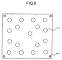
- Fig. 8 is a sectional view along line B-B of the lower end plate 62.
- the lower end plate 62 has a guide hole 77 for guiding the absorbing rod 11.
- the guide hole 77 is provided corresponding to the position of the control rod guide pipe 5 and measuring pipe 6.
- the width of the upper end plate 61 and lower end plate 62 in the horizontal direction must be wide enough for allowing to be inserted from the upper opening of the upper nozzle 2, and the width is required to be at least enough for forming the guide hole 77 of the control rod guide pipe 5 and measuring pipe 6.
- a suspension hole 78 is provided almost in the center of the upper end plate 61.
- the inner wall of the suspension hole 78 has a dent 70 for hooking the claw 69 of the clamping tool 65 mentioned below.
- the clamping tool 65 rotates freely about the fulcrum 68 provided in a flat suspension plate 60 corresponding to the upper end plate 61, and it is provided in the upper part of the clamping tool 65, and the claw 69 provided in the lower pat of the clamping tool 65 is always opened by a tension spring 66 for pulling the upper pat of the clamping tool 65 mutually, so that the upper end plate 61 is held.
- the upper part of the clamping tool 65 When canceling holding of the upper end plate 61, that is, when separating the upper end plate 61 and lower end plate 62 from the suspension portion 64, the upper part of the clamping tool 65 is pushed open by overcoming the tensile force of the tension spring 66, by means of an air cylinder 67 for connecting the upper part of the clamping tool 65 mutually. As a result, the clamp 69 is released from the dent 70, and separated through a suspension hole 78 from each other.
- the suspension plate 60 and load cell 81 are suspended through a rope 84, and further the load cell 81 is suspended on a hook 82 through a rope 83 while detecting the suspended load, and this hook 82 is connected to a hoist not shown in the drawing.
- the hoist moves the entire suspension portion 64, in particular, moves vertically, and can move the upper end plate 61 and lower end plate 62 coupled together through the clamping tool 65 simultaneously.
- an optical fiber 71 is wound through a take-up unit 73 corresponding to the vertical motion of the lower end plate 62.
- the optical fiber 71 penetrates the through-hole 76 of the suspension plate 60 and through-hole 75 of the upper end plate 61, and extends up to an imaging hole 94 of the lower end plate 62.
- At the leading end of the optical fiber 71 there is a lens 72 of the optical fiber 71, and the lens 72 is directed downward through the imaging hole 94.
- a weight 91 is provided at the leading end of the optical fiber 71, and the lens 72 of the optical fiber 71 is pressed, so that the image may be stably taken.
- the other end of the optical fiber 71 is connected to the imaging unit not shown through the take-up unit 73, and the image near the lens 72 is taken by the camera or the like.
- the suspension plate 60 further has a detector 92 having a protrusion in the lower part.
- a detecting protrusion 93 is formed, and this detecting protrusion 93 may abut against the lower protrusion of the detector 92 by way of the through-hole 74 of the upper end plate 61.
- the state shown in Fig. 7 is an initial state of insertion, and the upper end plate 61 is coupled to the suspension portion 64, and the suspender 63 is extended to the full extent. In this state, the relative configuration of the position of the lower end plate 62 and the position of the upper nozzle 2 is detected through the lens 72 of the optical fiber 71.
- This relative configuration is detected by image processing, and it is determined whether the relative position deviation is less than a specified value or not, for example, by pattern matching, and when less than the specified value, it is judged that the lower end plate 62 and upper nozzle 2 are matched in position, that is, the guide hole 77 of the lower end plate 62 and the control rod guide pipe 5 of the upper nozzle 2 are matched in relative configuration.
- a reference image without deviation in relative position is obtained. If the lower end plate 62 is deviated in position to upper right direction in the drawing, as shown in Fig. 9B, the passage 21 and control rod guide pipe 5 are positioned at the lower right corner in the drawing, and the region of a nozzle casing 100 at the upper end of the wall of the upper nozzle 2 is wider. On the other hand, when the lower end plate 62 is deviated to the lower right position in the drawing, as shown in Fig. 9C, the passage 21 and the control rod guide pipe 5 are positioned at the upper right corner in the drawing, so that the region of the nozzle casing 100 is smaller.
- the position deviation of the lower end plate 62 that is, the position deviation of the absorbing rod 11 can be detected by matching the patterns of the image shown in Fig. 9B and Fig. 9C and the reference image shown in Fig. 9A.
- This position deviation information is transmitted to the operator handling the hoist, and this operator handles so as to eliminate the position deviation by manipulating the hoist on the basis of this information of position deviation.
- the operator When correction of position deviation is over, the operator lowers the hoist, and also lowers the upper end plate 61, thereby lowering the absorbing rod 11, so that the absorbing rod 11 is inserted into the control rod guide pipe 5 and measuring pipe 6 through the guide hole 77.
- the lower end plate 62 is mounted on the inner upper side of the upper nozzle 2 at a position free from deviation of position.
- the absorbing rod 11 is inserted into the control rod guide pipe 5 and others, and the upper end plate 61 holding the absorbing rod 11 and the lower end plate 62 guiding the absorbing rod 11 settle within the upper nozzle 2, thereby not exceeding the shape of the upper nozzle 2. Therefore, these spent fuel assemblies are in the same shape as the spent fuel assemblies in which the absorbing rods 11 are not inserted.
- the abutting of the detector 92 and detecting protrusion 93 can be detected by magnetic or electric means.
- the distance can be measured by optical means, and it may be judged that the insertion is complete when the distance becomes shorter than a specified value.
- the upper end plate 61 and lower end plate 62 by a material having a neutron absorbing capability such as B-Al material, same as the absorbing rods 11, it is possible to reduce the thickness of the resin in the lid direction in the case of a wet cask for storing in a state immersed in water.
- a material having a neutron absorbing capability such as B-Al material
- the positions are corrected approximately, and the relative positions of the absorbing rods and control rod guide pipes 5 and others are matched, and further by using the tape shape of the lading end of the absorbing rods, the absorbing rods can be securely and easily inserted into the control rod guide pipes 5. Also by detecting the completion of insertion, safety in insertion can be assured.
- a forth embodiment is explained below.
- the second embodiment it is intended to store the spent fuel assemblies in the first embodiment into the cask.
- the forth embodiment specifies the method of storing spent fuel assemblies in the storage pool.
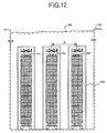
- Fig. 12 is a schematic diagram showing configuration when storing fuel assemblies 101 as spent fuel assemblies in a pool 102.
- the fuel assembly 101 in which the absorbing rod 11 shown in the first embodiment is inserted is stored in a rack cell in a rack 104 arranged in the pool 102 filled with water 103.
- the fuels are stored in the pool 103 while mutually keeping a safe spacing distance d for assuring the subcriticality of the fuels, but sine the absorbing rods 11 having neutron absorbing capability are inserted in the fuel assemblies 101, the spacing distance d may shorter than the spacing distance d when the absorbing rods 11 are not inserted.
- the fuel assemblies 101 can be arranged at high density, and the number of fuel assemblies 101 to be stored is increased, or the size of the pool 102 can be reduced.
- spent fuel assemblies for PWR of 14 ⁇ 14 are shown as examples, but not limited to this example, it is evident to be applicable similarly in other spent fuel assembles for PWR, such as 17 ⁇ 17 or 15 ⁇ 15 arrangement as shown in Fig. 16.
- this absorbing rod is inserted into the control rod guide pipe of spent fuel assemblies or the control rod guide pipe including the measuring pipe, and therefore the neutrons can be shielded effectively in the spent fuel assemblies.
- the absorbing rod of another aspect of the present invention is made of aluminum composite material or aluminum alloy formed by adding powder of boron or boron compound having a neutron absorbing performance to aluminum or aluminum alloy powder. Since the absorbing rod is made of such material, it does not get damaged by minor shocks during transportation. As a consequence, it is possible to maintain the neutron absorbing ability even during transport. For example, it is much safer and therefore preferable than an absorbing rod having a structure in which boron powder is filled inside a pipe.
- the cask of still another aspect of the present invention by inserting the absorbing rod group having a nearly same shape as the shape of a columnar control rod for PWR used in reactivity control of core in a reactor, and having a neutron shielding capability into the control rod guide pipe of spent fuel assemblies or the control rod guide pipe group including the measuring pipe, and putting the spent fuel assemblies into the cask, the number of neutrons radiated outside from the spent fuel assemblies can be decreased, so that the spacing distance among spent fuel assemblies can be shortened, and therefore it is effective to increase the number of spent fuel assemblies to be accommodated in the cavity of the shell main body having the neutron shield on the outer circumference and shielding the gamma-rays, or in the same number of containers as in the prior art, the cavity shape of the shell main body may be reduced or the thickness of the neutron shield on the outer circumference can be reduced, thereby reducing the overall size of the cask.
- the absorbing rod is used as the control rod for PWR, and the control rods are kept inserted in the spent fuel assemblies, and therefore the recovered control rods can be utilized effectively.
- the equivalent thickness corresponding to the neutron absorbing capability or neutron moderating capability of the plates or square pipes for composing the basket for holding the spent fuel assemblies for PWR in the cask, of the portion corresponding to the sectional area of the absorbing rod inserted in the spent fuel assemblies for PWR, is reduced for the portion of the equivalent sectional area corresponding to the neutron absorbing capability or neutron moderating capability of the absorbing rod inserted in the spent fuel assemblies for PWR, thereby forming in a basket shape
- the water zones provided in the basket for PWR high in uranium enrichment factor in particular, can be further reduced in height, or the basket may be formed even by eliminating the water zones, and therefore the shape of the basket for PWR high in uranium enrichment factor may be formed same as a simple shape of basket for BWR, and the efficiency of basket production can be enhanced.
- the absorbing rod and basket are composed of an Al composite material or an Al alloy formed by adding powder of B or B compound having a neutron absorbing performance to Al or Al alloy powder, neutrons are absorbed in side and around the spent fuel assemblies, and therefore, aside from efficient neutron absorption in and around the spent fuel assemblies, since the absorbing rods are inserted in the fuel assemblies, the required performance in strength is lower, so that the weight reduction can be promoted.
- the relative positions of the through-hole group of the guide member and the control rod guide pipe group of the spent fuel assemblies are adjusted on the basis of the result of detection by the position detection unit, and the absorbing rod block is lowered so that the through-hole group acts as a guide hole, and the long absorbing rod group can be inserted securely into the control rod guide pipe or the control rod guide pipe including the measuring pipe, and therefore the absorbing rods can be inserted into the control rod guide pipes and others easily and securely, so that the efficiency of inserting job can be enhanced.
- the distance detection unit detects when the distance between the suspender and the fixing member comes within a specific distance, and it is known that the absorbing rod group is securely inserted into the control rod guide pipe, so that dropping of absorbing rod group in the midst of insertion is prevented, and therefore the efficiency of inserting job can be enhanced, and the end of series of inserting job can be detected securely, so that the inserting job can be done safely.
- the conveying and storing method of still another aspect of the present invention at the inserting step, by inserting an absorbing rod group having a nearly same shape as the shape of a columnar control rod for PWR used in reactivity control of core in a reactor, and having a neutron shielding capability, into a control rod guide pipe group including a measuring pipe of spent fuel assemblies for PWR, and at the conveying and storing step, by conveying and storing the spent fuel assemblies for PWR in a state in which the absorbing rod group is inserted, the spacing distance between spent fuel assemblies can be shortened, and therefore the density of the spent fuel assemblies for PWR when conveying or storing the spent fuel assemblies for PWR can be enhanced, and efficient conveying or storing may be possible.
- control rods for PWR are recovered, the absorbing rod is used as the control rod for PWR, and the control rods are kept inserted in the spent fuel assemblies, and therefore the recovered control rods can be utilized effectively.
Landscapes
- Physics & Mathematics (AREA)
- Engineering & Computer Science (AREA)
- General Engineering & Computer Science (AREA)
- High Energy & Nuclear Physics (AREA)
- Plasma & Fusion (AREA)
- Monitoring And Testing Of Nuclear Reactors (AREA)
- Devices And Processes Conducted In The Presence Of Fluids And Solid Particles (AREA)
Abstract
Description
- The present invention relates to an absorbing rod having a neutron absorbing capability to be inserted into a control rod guide pipe of spent fuel assemblies, an inserting apparatus for inserting the absorbing rod into the control rod guide pipe, a cask for containing, conveying and storing the spent fuel assemblies, and a conveying and storing method of spent fuel assemblies.
- Fuel assemblies consumed and no longer usable in a terminal stage of fuel cycle are called spent fuels. Spent fuels contain fission products and other highly radioactive substances, and must be cooled thermally, and hence they are cooled for a specific period in a cooling pit at a nuclear power plant. Then they are transferred into a shielding container called cask, and conveyed and stored at reprocessing plant or storage facility by means of truck or ship. When transferring the spent fuel assemblies into the cask, a holding element having a lattice section called basket is used. Each one of the spent fuel assemblies is put into each of the cells formed as plural storing spaces in the basket, and a proper holding strength to withstand vibration during transportation is assured.
- Various types of casks are disclosed in publications such as "Atomic Eye" (Nikkan Kogyo Shuppan Production, April 1, 1998) and Japanese Patent Application Laid-open No. 62-242725.
- Fig. 13 is a perspective view of an example of a cask. Fig. 14 is art axial direction sectional view of the cask shown in Fig. 13. A
cask 500 is composed of a shellmain body 501, aresin 502 which is a neutron shield provided on the outer circumference of the shellmain body 501, itsouter tube 503,bottom 504 andlid 505. The shellmain body 501 andbottom 504 are carbon steel forged parts which are gamma-ray shielding materials. Thelid 505 is composed of aprimary lid 506 and asecondary lid 507 made of stainless steel or the like. The shellmain body 501 andbottom 504 are bonded by butt welding. Theprimary lid 506 andsecondary lid 507 are fixed to the shellmain body 501 by means of stainless steel bolts. A metal O-ring is interposed between thelid 505 and shellmain body 501, and the inside is kept airtight. - Many
inner fins 508 are provided, between the shellmain body 501 andouter tube 503, for heat conduction. Theinner fins 508 are made of copper in order to enhance the heat conduction efficiency. Theresin 502 is injected into the space formed by theinner fins 508 in fluid state, and is solidified by thermosetting reaction or the like. Abasket 509 is a bundle structure of 69square pipes 510 as shown in Fig. 14, and is inserted into acavity 511 in the shellmain body 501. - The
square pipes 510 are made of aluminum alloy mixing neutron absorbing material (boron: B) so that the inserted spent fuel assemblies may not reach the criticality. At both sides of the caskmain body 512, moreover, a trunnion 513 (only one is shown) for suspending thecask 500. At both ends of the caskmain body 512, abuffer materials 514 assembling wood or other shock-absorbing materials are provided (only one side is shown).Reference numeral 515 is a cell for accommodating the spent fuel assemblies. - The light-water type reactor is classified into the boiling water reactor (BWR) and pressurized water reactor (PWR). This
cask 500 is the cask for storing the spent fuel assemblies used in BWR. The structure of the fuel assembly for BWR is shown in Fig. 15. The fuel assembly for BWR has fourchannel boxes 601 arranged in lattice, and across-shaped control rod 608 is located in the central area, and the reactivity offuel rods 603 is controlled by the vertical move of thecontrol rod 608. - The
fuel assembly 600 has 8 × 8fuel rods 603 arranged in lattice. Eachfuel rod 603 is a long bar of about 4 meters. Asupport lattice 607 is provided for supporting thefuel rod 603. In eachfuel rod 603, pluralcolumnar pellets 631 formed by sintering powder of uranium oxide are inserted as fuel into a cylindricalclad pipe 633 composed of zirconium alloy, and held by aspring 632 inserted in the upper part of theclad pipe 633. Ahandle 610 is used for lifting up and down thefuel assembly 600. The spent fuel assembly inserted in thecell 515 in thiscask 500 is a fuel assembly forBWR 600 shown in Fig. 15. - By contrast, the fuel assembly shown in Fig. 16 is used in PWR. In this fuel assembly for PWR 700,
control rods 708 are properly distributed amongfuel rods 703, and thefuel rods 703 andcontrol rods 708 are arranged in 17 × 17 lattice form. In this 17 × 17 fuel assembly 700, one measuring pipe is disposed in the center, and 24control rods 708 are distributed. - The reactivity of the core can be controlled by moving the
control rod 708 up or down. Eachfuel rod 703 is a long bar of about 4 meters same as thefuel rod 603 for BWR, and hence asupport lattice 707 for supporting thefuel rod 703 is provided. In eachfuel rod 703,plural pellets 731 are inserted into acylindrical clad pipe 733 composed of zirconium alloy, and held by aspring 732 inserted in the upper part of theclad pipe 733. In this cask, 70 units of spent fuel assemblies are contained in the cell. - Fig. 17 is an axial direction sectional view of the cask for PWR. As shown in Fig. 17, a
cavity 811 of acask 800 for PWR contains abasket 809 forming acell 815 of rectangular section by alternately combiningplates 817 extending in the radial direction. Eachplate 817 is composed of aluminum alloy mixing B as neutron absorbing material, same as thesquare pipes 510 for BWR. - However, each
plate 817 has a through-hole ofcooling water passage 816 extending in the axial direction, known as water zone, and when cooling the spent fuel assemblies, each basket cell and this through-hole are filled with water to moderate neutrons, so that the neutrons may be absorbed efficiently by theplates 817 and theresin 802. The water filling thecooling water passage 816 is discharged after a specified cooling period, and the passage is dried. - This
cooling water passage 816 is required because the uranium enrichment factor of fuel assembly for PWR is higher than that of the fuel assembly for BWR, the uranium charging amount per fuel assembly is larger, the sectional area of the fuel assembly is wider, and hence the reactivity is higher in the system arranging these assemblies. The distance dd shown in Fig. 17 is such a distance that it assures the subcriticality of the spent fuel assembly. The distance dd for PWR is required to be longer than the same for BWR. Thecells 815 are not arranged in lattice but are deviated in position, which is intended to dispose the spent fuel assemblies for PWR, having a wider sectional area as compared with the spent fuel assemblies for BWR, efficiently in thecavity 811. - In the spent fuel assemblies for PWR mentioned above, the
control rods 708 distributed among thefuel rods 703 arranged in lattice are extracted, and the spent fuel assemblies 700 from which thecontrol rods 708 are extracted are inserted and stored in thecells 815 formed by thebasket 809 in thecask 800. - Therefore, the vacancies left over by the extracted
control rods 708 or measuring rod, not shown, in the spent fuel assemblies are dead spaces, and it is desired to utilize these spaces effectively. - Further, the plates or square pipes for forming the basket for PWR are required to form the
cooling water passage 816, and formation of plates or square pipes is more complicated as compared with formation of plates or square pipes for BWR, and it takes much time and labor. - Besides, the sectional area of the spent fuel assemblies for PWR is rectangular and wide, and also the
cooling water passage 816 is needed, and hence the accommodation efficiency of the spent fuels in the cask is poor. - It is an object of the present invention to provide an absorbing rod capable of heightening the accommodation density of spent fuel assemblies, by effectively utilizing the control rod inserting space and measuring rod inserting space existing in the spent fuel assemblies for PWR and shortening the distance dd for assuring the subcriticality among the spent fuel assemblies, its inserting apparatus, cask, and conveying and storing method of spent fuel assemblies.
- The absorbing rod according to one aspect of this invention has nearly the same shape as the shape of a columnar control rod for PWR. Further, the absorbing rod has the ability to shield the neutrons. Since the absorbing rod has nearly the same shape as the shape of the columnar control rod for PWR, this absorbing rod can be inserted into the control rod guide pipe of spent fuel assemblies or the control rod guide pipe including the measuring pipe.
- The absorbing rod according to another aspect of this invention is made of aluminum composite material or aluminum alloy formed by adding powder of boron or boron compound having a neutron absorbing performance to aluminum or aluminum alloy powder. Since the absorbing rod is made of such material, it does not get damaged by minor shocks during transportation. As a consequence, it is possible to maintain the neutron absorbing ability even during transport. For example, it is much safer and therefore preferable than an absorbing rod having a structure in which boron powder is filled inside a pipe.
- The cask according to still another aspect of this invention comprises an absorbing rod group having nearly the same shape as the shape of a columnar control rod for PWR. Further, the absorbing rod group has the ability to shield the neutrons. The spent fuel assemblies is stored in the cask. Accordingly, the number of neutrons radiated from the spent fuel assemblies can be decreased. Further, the spacing between the spent fuel assemblies can be shortened.
- The inserting apparatus according to still another aspect of this invention comprises a position detection unit which detects the distance between a through-hole group of the guide member and the control rod guide pipe group of the spent fuel assemblies, and their relative positions are adjusted accordingly. Further, the absorbing rod block is lowered so that the through-hole group acts as a guide hole, and the long absorbing rod group can be inserted securely into the control rod guide pipe or the control rod guide pipe including the measuring pipe.
- The conveying and storing method of spent fuel assemblies according to still another aspect of this invention comprises a step of inserting an absorbing rod group having a nearly same shape as the shape of a columnar control rod for PWR used in reactivity control of core in a reactor, and having a neutron shielding capability, into a control rod guide pipe group including a measuring pipe of spent fuel assemblies for PWR. Further, the spent fuel assemblies for PWR are conveyed and stored in a state in which the absorbing rod group is inserted. Accordingly, the distance between spent fuel assemblies can be shortened.
- Other objects and features of this invention will become apparent from the following description with reference to the accompanying drawings.
-
- Fig. 1 is a perspective view which shows the structure of a spent fuel assembly for PWR.
- Fig. 2 is a diagram which shows the structure of an absorbing rod block to be inserted in the spent fuel assembly and also explains how the absorbing rod block inserted in the spent fuel assembly.
- Fig. 3 is a plan of the spent fuel assembly.
- Fig. 4 is a sectional view along line A-A of support lattice.
- Fig. 5 is a diagram showing a structure of a fuel rod.
- Fig. 6 is a radial direction sectional view which shows the structure of a cask according to the present invention.
- Fig. 7 is a diagram which shows the structure of an inserting apparatus according to the present invention.
- Fig. 8 is a sectional view along line B-B of a lower end plate.
- Fig. 9A to Fig. 9C are examples of the photographed images.
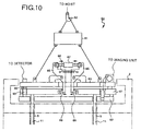
- Fig. 10 is a diagram which shows the inserting apparatus right after completion of insertion.
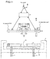
- Fig. 11 is a diagram which shows the structure of spent fuel assembly after completion of insertion and a structure of a suspender.
- Fig. 12 is a schematic diagram which shows storage configuration of spent fuel assemblies in a storage pool.
- Fig. 13 is a perspective view showing a structure of a cask for BWR.
- Fig. 14 is a radial direction sectional view which shows the structure of the cask shown in Fig. 13.
- Fig. 15 is a diagram showing a structure of a fuel assembly for BWR.
- Fig. 16 is a diagram showing a structure of a fuel assembly for PWR.
- Fig. 17 is a radial direction sectional view which shows structure of a conventional cask for PWR.
-
- Preferred embodiments of the absorbing rod, the inserting apparatus (apparatus for inserting the absorbing rod), the cask, and the method of conveying and storing the spent fuel assemblies according to the invention are explained in detail below while referring to the accompanied drawings. However, this invention is not limited only to these embodiments.
- A spent fuel assembly conforming to the invention is explained in the first place. Fig. 1 is a perspective view showing a general view of a spent fuel assembly for PWR. As shown in Fig. 1, a fuel assembly 1, which is a spent fuel assembly, is formed as a lattice bundling of
fuel rods 4, controlrod guide pipes 5, and measuringpipes 6, being arranged in a matrix section of 14 × 14. This matrix arrangement is supported by support lattices 7 provided at proper positions in the longitudinal direction of thefuel rods 4, controlrod guide pipes 5, and measuringpipes 6. The controlrod guide pipes 5 and measuringpipes 6 are supported by anupper nozzle 2 and alower nozzle 3. - That is, the control
rod guide pipes 5 and measuringpipes 6 are cylindrical in shape, and held by through-holes between theupper nozzle 2 andlower nozzle 3 provided corresponding to the matrix arrangement positions of the controlrod guide pipes 5 and measuringpipes 6. In the controlrod guide pipes 5, control rods having a neutron absorbing capability in the reactor are inserted, and the reactivity of the core is controlled by the number and depth of insertion of control rods. The controlrod guide pipes 5 are dispersed on the matrix arrangement. In the measuringpipes 6, measuring rods not shown in the drawing are inserted periodically in the reactor for measuring the temperature and radiation dose, and the information for core management is obtained. However, when stored as spent fuel assembly, the control rods inserted in the controlrod guide pipes 5 are extracted, and similarly measuring rods are extracted from the measuringpipes 6. - Accordingly, as shown in Fig. 2, plural absorbing
rods 11 having the same columnar shape as the control rods and measuring rods to be inserted in the controlrod guide pipes 5 and measuringpipes 6 and having a neutron absorbing capability are newly prepared, and these absorbing rods are inserted into the controlrod guide pipes 5 and measuringpipes 6 of the fuel assembly 1. One end of each absorbingrod 11 is bonded to anend plate 12 which is a rectangular plate member to be inserted inside from the upper opening of theupper nozzle 2, and the other end is formed in a taper, so as to be inserted easily into the controlrod guide pipes 5 and measuringpipes 6. - The length of the absorbing
rod 11 is long enough to envelop the effective length of the fuel. The radius of the absorbingrod 11 is less then the inside diameter of the controlrod guide pipe 5 and measuringpipe 6, and is preferred to be closer to the inside diameter of the controlrod guide pipe 5 and measuringpipe 6 as far as possible, but a certain clearance is required considering the length of about 4 meters. - Fig. 3 is a plan of the fuel assembly 1 shown in Fig. 2. The
upper nozzle 2 shown in Fig. 3 corresponds to the matrix arrangement, in which the controlrod guide pipes 5 and measuringpipes 6 are disposed. There are plural through-holes forlight water passages 21 in the reactor. The absorbingrod 11 is penetrating through the controlrod guide pipe 5 and measuringpipe 6. - Fig. 4 is a sectional view along line A-A of support lattice 7 of the fuel assembly 1 shown in Fig. 2. The support lattice 7 supports the lattice state of 14 × 14 consisting of
fuel rods 4, controlrod guide pipes 5 and measuringpipes 6. The absorbingrods 11 penetrate through the controlrod guide pipes 5 and measuringpipes 6 of the support lattice 7 shown in Fig. 4. - Therefore, the
end plate 12 shown in Fig. 2 is bonded with the absorbingrod 11 so that the absorbingrod 11 may be held in the state inserted in the controlrod guide pipe 5 and measuringpipe 6. By using an absorbing rod block 10 formed by boding plural absorbingrods 11 andend plates 12, a plurality of absorbingrods 11 can be inserted in batch into the controlrod guide pipes 5 and measuringpipes 6. Alternatively, instead of bonding the absorbingrods 11 by usingend plates 12, the absorbingrods 11 may be individually inserted into the controlrod guide pipes 5 and measuringpipes 6. However, when conveying the fuel assembly 1 in which the absorbingrods 11 are inserted, it is easier to hold the absorbingrods 11 by using the absorbing rod block 10. - Fig. 5 is a front view of the
fuel rod 4. In Fig. 5,plural pellets 31 are inserted into a cylindrical cladpipe 33 composed of zirconium alloy, and thepellets 31 are held by aspring 32 inserted in the upper part of the cladpipe 33. Thisfuel pipe 4 is mainly composed of the spent fuel assembly as mentioned above. - The absorbing
rod 11 is composed of aluminum composite material or aluminum alloy formed by adding powder of boron or boron compound having neutron absorbing capability, to the powder of aluminum or aluminum alloy, and it is designed not to reach the criticality from the inside of the spent fuel assembly. - The following material may preferably used as the aluminum composite material. In addition to adding the powder of boron or boron compound to the aluminum composite material, third particles of oxides may be added. Accordingly, mechanical alloying is performed and the strength of the material can be increased. To achieve this, powder of aluminum or aluminum alloy as the matrix material, boron or boron compound as the neutron absorber, and third particles as oxides, nitrates, carbides, borides are mixed in the Attriter pan.
- The amount of these third particles should preferably be greater than 0.1 weight percent and less than 30 weight percent. Such an amount is preferable because, if the amount is less than 0.1 weight percent, then there is not much effect on strengthening the material. On the other hand, if the amount is greater than 30 weight percent, then the property of the material to expand decreases. Further, it is preferable that the diameters of the third particles in the aluminum matrix is greater than 0.01 µm and less than 10 µm. The material having a diameter smaller than 0.01 µm is very costly and difficult to acquire. On the other hand, the material having a diameter greater than 10 µm does not contribute much to strengthening the material.
- The amount of boron or boron compound should preferably be greater than 1 weight percent and less than 20 weight percent. Such an amount is preferable because, if the amount is less than 1 weight percent, then it does not absorb the neutrons properly. On the other hand, if the amount is greater than 20 weight percent, then the property of the material to expand decreases. Further, it is preferable that the diameters of the boron or boron compound is greater than 0.01 µm and less than 100 µm. The material having a diameter smaller than 0.01 µm is very costly. On the other hand, the material having a diameter greater than 100 µm degrades the strength.
- Further, any material having a property to absorb the neutrons may be uses instead of boron or boron compound. That is, Cd, Hf, or rare earth elements having bigger neutron absorbing cross section may be used. For example, boron or boron compound are used in case of BWR, however, Ag-In-Cd compound are used in case of PWR. In the Ag-In-Cd compound, it is general that In is 15 weight present and Cd is 5 weight present. Further, carbides such as Eu, Sm, Gd may be used.
- Al2O3, ZrO2, SiO2, MgO, TiO2, Cr2O3 may be used as the oxides in the third particles. Si3N4, BN are the examples of nitrates that may be used. SiC, WC, Cr2C3 are the examples of carbides, and ZrBr2 is the example of boride that may be used. Further, it is not necessary to use only the third particles mentioned here. Any material may be used according to the need.
- Following material may be used as powder of aluminum or aluminum alloy. That is, pure aluminum (JIS 1xxx), Al-Cu aluminum compound (JIS 2xxx), Al-Mg aluminum compound (JIS 5xxx), Al-Mg-Si aluminum compound (JIS 6xxx), Al-Zn-Mg aluminum compound (JIS 7xxx), Al-Fe aluminum compound (Fe content between 1 to 10 weight percent). Further, Al-Mn aluminum compound (JIS 3xxx) also may be used. The material to be used may be selected depending upon the required strength, expansion, processing ability, and temperature resistance.
- A powder obtained by the rapid solidification has uniform and fine composition. Such a powder may be used in as powder of aluminum or aluminum alloy. Known methods such as unit roll method, double roll method, atomization methods such as air atomization or gas atomization may be used to obtain rapid solidification powders. It is preferable that the particles of the obtained powder of aluminum or aluminum alloy has a diameter of between 5 to 150 µm.
- If the diameter is less than 5 µm, then the particles come together and form a mass. Further, if the diameter is less than 5 µm then it is difficult to use the atomization methods (it is required to separate the minute powder and the coast increases). On the other hand, if the diameter is greater than 150 µm, then again there is a limitation on the use of the atomization method, and it becomes difficult to mix the material with the minute addition particles. The most preferable diameter is 50 to 120 µm. The cooling speed should be above 102 degree centigrade per second. Most preferably, the cooling speed should be above 103 degree centigrade per second.
- On the other hand, boron or boron compound has a property that it has great capability to absorb fast neutrons. B4C, B2O3 may be applied in the present invention. Out of these two, B4C has more boron content per unit weight. Therefore, B4C can absorb more neutrons with lesser quantity. Further, B4C has more hardness, and therefore, preferable.
- It is mentioned above that, the third particles are oxides, nitrates, carbides, borides. However, the particles other than these may be added. For, example, Zr or Ti may be added so as to increase the strength.
- The material mixed in the above-mentioned manner and amount is subjected to mechanical alloying in Attriter mill. A rotating mill or a vibrating mill may be used instead of Attriter mill. When subjected to mechanical alloying, aluminum and aluminum compound is crushed by the balls and become flat. Further, boron or boron compound and the third particles ground to still finer size and they uniformly enter into the voids in the aluminum matrix. These flattened particles become particles of normal shape containing aluminum or aluminum compound and the third particles.
- It is possible to increase the material strength greatly because of the addition of the third particles and subjecting to mechanical alloying. It was confirmed with an experiment that the material formed in this manner has about three times higher material strength than the material formed using the ordinary mixers (for example, cross-rotary mixer or V mixer). Further, boron or born compound having high hardness get dispersed finely and uniformly inside the matrix so that the cohesion of boron can be prevented. Further, property to squeeze out can be increased greatly. Accordingly, dice for squeeze out is not so worn-out due to friction.
- Further, when adding the third particles, aluminum or aluminum composite powder may be subjected to oxidation thereby creating a oxide layer on the surface of these particles, finely pulverize this oxide layer due to the mechanical alloying so as to cause the particles to disperse in the matrix. The oxidation of the aluminum or aluminum composite powder may be performed by heating in air. For example, aluminum or aluminum composite powder may be put into a furnace and agitated while being heated. When this process is carried out for a few hours, an oxide layer is formed on the surface of aluminum or aluminum compound.
- Thus, the absorbing
rods 11 is formed of aluminum composite material or aluminum alloy. Accordingly, it is light weight, has an ability to shield the neutrons, and the distance between the spent fuel assemblies can be decreased. In other words, if the same number of the spent fuel assemblies are to be used, then the cask becomes light-weight. Any material that has the property to absorb the neutrons may be used instead of aluminum composite material or aluminum alloy. Accordingly, thefuel rod 4 may itself be used instead of the absorbingrod 11. - According to the first embodiment, since the absorbing
rods 11 having neutron absorbing capability are inserted into the controlrod guide pipes 5 and measuringpipes 6 of spent fuel assemblies, the neutrons can be absorbed by effectively utilizing the space in the controlrod guide pipes 5 and measuringpipes 6, and emission of neutrons from the inside of the spent fuel assemblies can be reduced, and therefore the spacing distance for subcriticality between spent fuel assemblies can be shortened. Or, by using the absorbing rod block 10 bondingplural absorbing rods 11 byend plates 12, the absorbingrods 11 can be inserted in batch into the controlrod guide pipes 5 and measuringpipes 6, so that the working efficiency is enhanced. - A second embodiment is explained below. The second embodiment relates to a cask for accommodating the spent fuel assemblies in which absorbing
rods 11 of the first embodiment are inserted, which eliminates the cooling water passage provided in the plates of the basket in this cask. - Fig. 6 is a radial direction sectional view of the cask, which is an improvement of the conventional cask for PWR shown in Fig. 17. The
plate 817 shown in Fig. 17 is high in the uranium enrichment factor in the spent fuel assemblies for PWR, large in uranium charge amount per unit fuel assembly as compared with the fuel for BWR, and wide in the sectional area of fuel assembly, and hence the reactivity is high in the system arranging them, and therefore in order to absorb the neutrons efficiently by moderating the neutrons in cooling process, the coolingwater passage 816 is filed with water as neutron moderator. The spent fuel assemblies in which the absorbingrods 11 explained in the first embodiment are inserted contain neutron absorbing materials in the spent fuel assemblies, and hence the neutrons released outside from the spent fuel assemblies are decreased. - As a result, it is possible to shorten the spacing distance for controlling with the subcriticality in cooling of spent fuel assemblies, and hence it does not require
cooling water passage 816 in cooling process. Accordingly, theplates 50 for composing thebasket 49 of thecask 40 for PWR shown in Fig. 6 do not have cooling water passage same as in the basket structure for BWR. - Hence, in the
cask 40 for PWR shown in Fig. 6, although the capacity volume is same as in thecavity 811 of thecask 800 for PWR shown in Fig. 17, the thickness of theplates 50 can be reduced, so that more spent fuel assemblies can be accommodated. For example, in thecask 800 shown in Fig. 17, 19 spent fuel assemblies can be accommodated, whereas in thecask 40 shown in Fig. 6, 32 spent fuel assemblies can be accommodated. By using thecask 40 in the second embodiment, 13 more spent fuel assemblies can be accommodated. In other words, the degree of integration of spent fuel assemblies can be heightened. - In the basket of the same shape as shown in Fig. 17, when the spent fuel assemblies in the first embodiment are accommodated, emission of neutrons is decreased, and hence the resin thickness can be reduced. As a result, it is possible to reduce the entire size of the cask when accommodating the same number of spent fuel assemblies.
- In the second embodiment, the
cell 55 is composed by combining theplates 50 in lattice form. However, the cell may be formed with square pipes. - Further, when accommodating the spent fuel assemblies in the first embodiment, the thickness of the plates for composing the basket of the cask can be reduced corresponding to the neutron absorbing capability of the absorbing rods inserted in the spent fuel assemblies, so that the number of spent fuel assemblies accommodated in the cask can be increased. Further, it is not necessary to install the cooling water passage, which is the feature of the cask for PWR, in the plates or square pipes, and plates or square pipes of simple structure as in the plates or square pipes for BWR can be sued.
- A third embodiment is explained below. In the first embodiment, by using the absorbing rod block 10 composed of plural absorbing
rods 11, a plurality of absorbingrods 11 are inserted in batch to enhance the working efficiency. The third embodiment is further intended to insert spent fuel assemblies of plural absorbingrods 11 more easily, safely and securely. - Fig. 7 shows the structure of the inserting apparatus according to the third embodiment. This inserting apparatus comprises an
upper end plate 61 coupling the absorbingrod 11, alower end plate 62 for guiding the absorbingrod 11, and asuspender 64 for moving theupper end plate 61. - The
upper end plate 61 corresponds to the absorbing rod block 10. Theupper end plate 61 andlower end plate 62 are suspended by thesuspender 63. Fig. 8 is a sectional view along line B-B of thelower end plate 62. Thelower end plate 62 has aguide hole 77 for guiding the absorbingrod 11. Theguide hole 77 is provided corresponding to the position of the controlrod guide pipe 5 and measuringpipe 6. When theupper end plate 61 andlower end plate 62 are suspended by thesuspender 63, when stopping still or in the initial state, the leading end of the absorbingrod 11 must be at least inserted into theguide hole 77. The width of theupper end plate 61 andlower end plate 62 in the horizontal direction must be wide enough for allowing to be inserted from the upper opening of theupper nozzle 2, and the width is required to be at least enough for forming theguide hole 77 of the controlrod guide pipe 5 and measuringpipe 6. - A
suspension hole 78 is provided almost in the center of theupper end plate 61. The inner wall of thesuspension hole 78 has adent 70 for hooking theclaw 69 of theclamping tool 65 mentioned below. Theclamping tool 65 rotates freely about the fulcrum 68 provided in aflat suspension plate 60 corresponding to theupper end plate 61, and it is provided in the upper part of theclamping tool 65, and theclaw 69 provided in the lower pat of theclamping tool 65 is always opened by atension spring 66 for pulling the upper pat of theclamping tool 65 mutually, so that theupper end plate 61 is held. When canceling holding of theupper end plate 61, that is, when separating theupper end plate 61 andlower end plate 62 from thesuspension portion 64, the upper part of theclamping tool 65 is pushed open by overcoming the tensile force of thetension spring 66, by means of anair cylinder 67 for connecting the upper part of theclamping tool 65 mutually. As a result, theclamp 69 is released from thedent 70, and separated through asuspension hole 78 from each other. - The
suspension plate 60 andload cell 81 are suspended through arope 84, and further theload cell 81 is suspended on ahook 82 through arope 83 while detecting the suspended load, and thishook 82 is connected to a hoist not shown in the drawing. The hoist moves theentire suspension portion 64, in particular, moves vertically, and can move theupper end plate 61 andlower end plate 62 coupled together through theclamping tool 65 simultaneously. - On the
suspension plate 60, anoptical fiber 71 is wound through a take-upunit 73 corresponding to the vertical motion of thelower end plate 62. Theoptical fiber 71 penetrates the through-hole 76 of thesuspension plate 60 and through-hole 75 of theupper end plate 61, and extends up to animaging hole 94 of thelower end plate 62. At the leading end of theoptical fiber 71, there is alens 72 of theoptical fiber 71, and thelens 72 is directed downward through theimaging hole 94. Aweight 91 is provided at the leading end of theoptical fiber 71, and thelens 72 of theoptical fiber 71 is pressed, so that the image may be stably taken. The other end of theoptical fiber 71 is connected to the imaging unit not shown through the take-upunit 73, and the image near thelens 72 is taken by the camera or the like. - The
suspension plate 60 further has adetector 92 having a protrusion in the lower part. On thelower end plate 62 corresponding to thisdetector 92, a detectingprotrusion 93 is formed, and this detectingprotrusion 93 may abut against the lower protrusion of thedetector 92 by way of the through-hole 74 of theupper end plate 61. When this detectingprotrusion 93 and the lower protrusion of thedetector 92 abut against each other, the absorbingrod 11 is completely inserted into the controlrod guide pipe 5 and measuringpipe 6. This abutting is detected by thedetector 92, and the result of detection is issued to a detector not shown in the drawing. - Referring further to Fig. 9 to Fig. 11, the inserting operation of the absorbing
rod 11 by the inserting apparatus is explained. The state shown in Fig. 7 is an initial state of insertion, and theupper end plate 61 is coupled to thesuspension portion 64, and thesuspender 63 is extended to the full extent. In this state, the relative configuration of the position of thelower end plate 62 and the position of theupper nozzle 2 is detected through thelens 72 of theoptical fiber 71. This relative configuration is detected by image processing, and it is determined whether the relative position deviation is less than a specified value or not, for example, by pattern matching, and when less than the specified value, it is judged that thelower end plate 62 andupper nozzle 2 are matched in position, that is, theguide hole 77 of thelower end plate 62 and the controlrod guide pipe 5 of theupper nozzle 2 are matched in relative configuration. - More specifically, as shown in Fig. 9A, a reference image without deviation in relative position is obtained. If the
lower end plate 62 is deviated in position to upper right direction in the drawing, as shown in Fig. 9B, thepassage 21 and controlrod guide pipe 5 are positioned at the lower right corner in the drawing, and the region of anozzle casing 100 at the upper end of the wall of theupper nozzle 2 is wider. On the other hand, when thelower end plate 62 is deviated to the lower right position in the drawing, as shown in Fig. 9C, thepassage 21 and the controlrod guide pipe 5 are positioned at the upper right corner in the drawing, so that the region of thenozzle casing 100 is smaller. Therefore, the position deviation of thelower end plate 62, that is, the position deviation of the absorbingrod 11 can be detected by matching the patterns of the image shown in Fig. 9B and Fig. 9C and the reference image shown in Fig. 9A. This position deviation information is transmitted to the operator handling the hoist, and this operator handles so as to eliminate the position deviation by manipulating the hoist on the basis of this information of position deviation. - When correction of position deviation is over, the operator lowers the hoist, and also lowers the
upper end plate 61, thereby lowering the absorbingrod 11, so that the absorbingrod 11 is inserted into the controlrod guide pipe 5 and measuringpipe 6 through theguide hole 77. In this case, thelower end plate 62 is mounted on the inner upper side of theupper nozzle 2 at a position free from deviation of position. - When insertion of absorbing
rod 11 into the controlrod guide pipe 5 and others is over, the protrusion of thedetector 92 and the detectingprotrusion 93 abut against each other, and the result of detection is issued to the detector not shown. On the basis of this result of detection, the operator manipulates to extend theair cylinder 67, and eliminate hooking of theclaw 69. Then, the operator lifts the hoist, and separates theupper end plate 61 from thesuspension portion 64. Whether separated actually or not can be checked by theload cell 81. - As a result, as shown in Fig. 11, the absorbing
rod 11 is inserted into the controlrod guide pipe 5 and others, and theupper end plate 61 holding the absorbingrod 11 and thelower end plate 62 guiding the absorbingrod 11 settle within theupper nozzle 2, thereby not exceeding the shape of theupper nozzle 2. Therefore, these spent fuel assemblies are in the same shape as the spent fuel assemblies in which the absorbingrods 11 are not inserted. - Incidentally, the abutting of the
detector 92 and detectingprotrusion 93 can be detected by magnetic or electric means. Alternatively, using an optical detector as thedetector 92, the distance can be measured by optical means, and it may be judged that the insertion is complete when the distance becomes shorter than a specified value. - By forming the
upper end plate 61 andlower end plate 62 by a material having a neutron absorbing capability such as B-Al material, same as the absorbingrods 11, it is possible to reduce the thickness of the resin in the lid direction in the case of a wet cask for storing in a state immersed in water. - According to the third embodiment, by detecting the relative position deviation of the absorbing rods and control
rod guide pipes 5 and others by using the inserting apparatus, the positions are corrected approximately, and the relative positions of the absorbing rods and controlrod guide pipes 5 and others are matched, and further by using the tape shape of the lading end of the absorbing rods, the absorbing rods can be securely and easily inserted into the controlrod guide pipes 5. Also by detecting the completion of insertion, safety in insertion can be assured. - A forth embodiment is explained below. In the second embodiment, it is intended to store the spent fuel assemblies in the first embodiment into the cask. However, the forth embodiment specifies the method of storing spent fuel assemblies in the storage pool.
- Fig. 12 is a schematic diagram showing configuration when storing
fuel assemblies 101 as spent fuel assemblies in apool 102. As shown in Fig. 12, thefuel assembly 101 in which the absorbingrod 11 shown in the first embodiment is inserted is stored in a rack cell in arack 104 arranged in thepool 102 filled withwater 103. Herein, the fuels are stored in thepool 103 while mutually keeping a safe spacing distance d for assuring the subcriticality of the fuels, but sine the absorbingrods 11 having neutron absorbing capability are inserted in thefuel assemblies 101, the spacing distance d may shorter than the spacing distance d when the absorbingrods 11 are not inserted. - Therefore, according to the forth embodiment, the
fuel assemblies 101 can be arranged at high density, and the number offuel assemblies 101 to be stored is increased, or the size of thepool 102 can be reduced. - In the first to forth embodiments, spent fuel assemblies for PWR of 14 × 14 are shown as examples, but not limited to this example, it is evident to be applicable similarly in other spent fuel assembles for PWR, such as 17 × 17 or 15 × 15 arrangement as shown in Fig. 16.
- As described herein, according to the absorbing rod of one aspect of the present invention, using the absorbing rod having a nearly same shape as the shape of a columnar control rod for PWR used in reactivity control of core in a reactor, and having a neutron shielding capability, this absorbing rod is inserted into the control rod guide pipe of spent fuel assemblies or the control rod guide pipe including the measuring pipe, and therefore the neutrons can be shielded effectively in the spent fuel assemblies.
- According to the absorbing rod of another aspect of the present invention, it is made of aluminum composite material or aluminum alloy formed by adding powder of boron or boron compound having a neutron absorbing performance to aluminum or aluminum alloy powder. Since the absorbing rod is made of such material, it does not get damaged by minor shocks during transportation. As a consequence, it is possible to maintain the neutron absorbing ability even during transport. For example, it is much safer and therefore preferable than an absorbing rod having a structure in which boron powder is filled inside a pipe.
- According to the cask of still another aspect of the present invention, by inserting the absorbing rod group having a nearly same shape as the shape of a columnar control rod for PWR used in reactivity control of core in a reactor, and having a neutron shielding capability into the control rod guide pipe of spent fuel assemblies or the control rod guide pipe group including the measuring pipe, and putting the spent fuel assemblies into the cask, the number of neutrons radiated outside from the spent fuel assemblies can be decreased, so that the spacing distance among spent fuel assemblies can be shortened, and therefore it is effective to increase the number of spent fuel assemblies to be accommodated in the cavity of the shell main body having the neutron shield on the outer circumference and shielding the gamma-rays, or in the same number of containers as in the prior art, the cavity shape of the shell main body may be reduced or the thickness of the neutron shield on the outer circumference can be reduced, thereby reducing the overall size of the cask.
- According to the cask of still another aspect of the present invention, when the control rods for PWR are recovered, the absorbing rod is used as the control rod for PWR, and the control rods are kept inserted in the spent fuel assemblies, and therefore the recovered control rods can be utilized effectively.
- Further, since the equivalent thickness corresponding to the neutron absorbing capability or neutron moderating capability of the plates or square pipes for composing the basket for holding the spent fuel assemblies for PWR in the cask, of the portion corresponding to the sectional area of the absorbing rod inserted in the spent fuel assemblies for PWR, is reduced for the portion of the equivalent sectional area corresponding to the neutron absorbing capability or neutron moderating capability of the absorbing rod inserted in the spent fuel assemblies for PWR, thereby forming in a basket shape, the water zones provided in the basket for PWR high in uranium enrichment factor, in particular, can be further reduced in height, or the basket may be formed even by eliminating the water zones, and therefore the shape of the basket for PWR high in uranium enrichment factor may be formed same as a simple shape of basket for BWR, and the efficiency of basket production can be enhanced.
- Further, since the absorbing rod and basket are composed of an Al composite material or an Al alloy formed by adding powder of B or B compound having a neutron absorbing performance to Al or Al alloy powder, neutrons are absorbed in side and around the spent fuel assemblies, and therefore, aside from efficient neutron absorption in and around the spent fuel assemblies, since the absorbing rods are inserted in the fuel assemblies, the required performance in strength is lower, so that the weight reduction can be promoted.
- According to the inserting apparatus of still another aspect of the present invention, the relative positions of the through-hole group of the guide member and the control rod guide pipe group of the spent fuel assemblies are adjusted on the basis of the result of detection by the position detection unit, and the absorbing rod block is lowered so that the through-hole group acts as a guide hole, and the long absorbing rod group can be inserted securely into the control rod guide pipe or the control rod guide pipe including the measuring pipe, and therefore the absorbing rods can be inserted into the control rod guide pipes and others easily and securely, so that the efficiency of inserting job can be enhanced.
- Further, the distance detection unit detects when the distance between the suspender and the fixing member comes within a specific distance, and it is known that the absorbing rod group is securely inserted into the control rod guide pipe, so that dropping of absorbing rod group in the midst of insertion is prevented, and therefore the efficiency of inserting job can be enhanced, and the end of series of inserting job can be detected securely, so that the inserting job can be done safely.
- According to the conveying and storing method of still another aspect of the present invention, at the inserting step, by inserting an absorbing rod group having a nearly same shape as the shape of a columnar control rod for PWR used in reactivity control of core in a reactor, and having a neutron shielding capability, into a control rod guide pipe group including a measuring pipe of spent fuel assemblies for PWR, and at the conveying and storing step, by conveying and storing the spent fuel assemblies for PWR in a state in which the absorbing rod group is inserted, the spacing distance between spent fuel assemblies can be shortened, and therefore the density of the spent fuel assemblies for PWR when conveying or storing the spent fuel assemblies for PWR can be enhanced, and efficient conveying or storing may be possible.
- Further, when the control rods for PWR are recovered, the absorbing rod is used as the control rod for PWR, and the control rods are kept inserted in the spent fuel assemblies, and therefore the recovered control rods can be utilized effectively.
- Although the invention has been described with respect to a specific embodiment for a complete and clear disclosure, the appended claims are not to be thus limited but are to be construed as embodying all modifications and alternative constructions that may occur to one skilled in the art which fairly fall within the basic teaching herein set forth.
Claims (12)
- An absorbing rod having a nearly the same shape as the shape of a columnar control rod for PWR used in reactivity control of core in a reactor, and having a neutron shielding capability.
- The absorbing rod according to claim 1, further comprising a fixing member for fixing said absorbing rod at a position corresponding to a control rod guide pipe of spent fuel assemblies for PWR or a sectional position of the control rod guide pipe including a measuring pipe.
- The absorbing rod according to claim 1, wherein said absorbing rod is composed of aluminum composite material or aluminum alloy formed by adding powder of boron or boron compound having a neutron absorbing performance to aluminum or aluminum alloy powder.
- An absorbing rod which is to be inserted into a control rod guide pipe of spent fuel assemblies or a measuring pipe, whereinsaid absorbing rod is composed of aluminum composite material or aluminum alloy formed by adding powder of boron or boron compound having a neutron absorbing performance to aluminum or aluminum alloy powder, andsaid absorbing rod is used, when transporting the spent fuel assemblies by storing into a cask, by inserting said absorbing rod into said control rod guide pipe or said measuring pipe.
- A cask comprising:an absorbing rod group, to be inserted into a control rod guide pipe group including a control rod guide pipe or a measuring pipe of spent fuel assemblies for PWR, having a nearly same shape as the shape of a columnar control rod for PWR used in reactivity control of core in a reactor, and having a neutron shielding capability;spent fuel assemblies for PWR having a control rod guide pipe in which said absorbing rod group is inserted or a control rod guide pipe group including a measuring pipe;a basket forming a lattice cell for accommodating the spent fuel assemblies for PWR in which said absorbing rod group is inserted;a shell main body accommodated in said basket, and having a neutron shield on the outer circumference, for shielding gamma-rays; anda detachable lid provided in an opening of said shell main body for putting the spent fuel assemblies for PWR in which said absorbing rod group is inserted, in and out of said lattice cell.
- The cask according to claim 5, wherein said absorbing rod is a control rod for PWR.
- The cask according to claim 5, wherein the equivalent thickness corresponding to the neutron absorbing capability or neutron moderating capability of the plates or square pipes for composing the basket for holding the spent fuel assemblies for PWR in the cask, of the portion corresponding to the sectional area of the absorbing rod inserted in the spent fuel assemblies for PWR, is reduced for the portion of the equivalent sectional area corresponding to the neutron absorbing capability or neutron moderating capability of the absorbing rod inserted in the spent fuel assemblies for PWR.
- The cask according to claim 5, wherein said absorbing rod is composed of aluminum composite material or an aluminum alloy formed by adding powder of boron or born compound having a neutron absorbing performance to aluminum or aluminum alloy powder.
- An inserting apparatus comprising:an absorbing bar element having a nearly same shape as the shape of a columnar control rod for PWR used in reactivity control of core, at a position corresponding to a control rod guide pipe of spent fuel assemblies for PWR or a sectional position of the control rod guide pipe including a measuring pipe, capable of inserting the fixing member into an upper nozzle through the upper nozzle opening of the spent fuel assemblies for PWR, by fixing the absorbing rod group having a neutron shielding capability by means of the fixing member;a guide member which can be inserted into the upper nozzle through the upper nozzle opening of the spent fuel assemblies for PWR, having a through-hole for inserting said absorbing rod group into the control rod guide pipe or a position corresponding to the sectional position of the control rod guide pipe including the measuring pipe, so as to be suspended on said fixing member in a state of the leading end of the absorbing rod group being inserted into the through-hole when standing still;a suspender detachably suspending the fixing member of said absorbing rod block and moving the absorbing rod block vertically when mounting, anda position detection unit provided in said guide member which detects the relative configuration of the location of the through-hole group provided in the guide member and the location of the corresponding control rod guide pipe group of the spent fuel assemblies for PWR,
wherein the relative positions of the through-hole group and control rod guide pipe group are adjusted on the basis of the result of detection by said position detection unit, and the absorbing rod group is lowered to insert the absorbing rod group into the control rod guide pipe or the control rod guide pipe including the measuring pipe. - The inserting apparatus according to claim 9, further comprising a distance detection unit which detects whether the distance between the suspender and the fixing member is within a specific range or not.
- A conveying and storing method of spent fuel assemblies comprising:a step of inserting an absorbing rod group having a nearly same shape as the shape of a columnar control rod for PWR used in reactivity control of core in a reactor, and having a neutron shielding capability, into a control rod guide pipe group including a measuring pipe of spent fuel assemblies for PWR; anda step of conveying and storing the spent fuel assemblies for PWR in a state in which said absorbing rod group is inserted.
- The conveying and storing method of spent fuel assemblies according to claim 11, wherein said absorbing rod is a control rod for PWR.
Applications Claiming Priority (2)
| Application Number | Priority Date | Filing Date | Title |
|---|---|---|---|
| JP31171399A JP3297412B2 (en) | 1999-11-01 | 1999-11-01 | Neutron absorption rod, insertion device, cask, and method for transporting and storing spent nuclear fuel assemblies |
| JP31171399 | 1999-11-01 |
Publications (2)
| Publication Number | Publication Date |
|---|---|
| EP1096507A1 true EP1096507A1 (en) | 2001-05-02 |
| EP1096507B1 EP1096507B1 (en) | 2006-01-04 |
Family
ID=18020584
Family Applications (1)
| Application Number | Title | Priority Date | Filing Date |
|---|---|---|---|
| EP00122355A Expired - Lifetime EP1096507B1 (en) | 1999-11-01 | 2000-10-24 | An absorbing rod, an apparatus for inserting a group of absorbing rods in a spent fuel assembly, a cask, and a method of conveying and storing spent fuel assemblies |
Country Status (7)
| Country | Link |
|---|---|
| US (1) | US6891914B1 (en) |
| EP (1) | EP1096507B1 (en) |
| JP (1) | JP3297412B2 (en) |
| KR (1) | KR20010060217A (en) |
| AT (1) | ATE315270T1 (en) |
| DE (1) | DE60025298T2 (en) |
| ES (1) | ES2254099T3 (en) |
Cited By (7)
| Publication number | Priority date | Publication date | Assignee | Title |
|---|---|---|---|---|
| RU2462775C1 (en) * | 2011-04-13 | 2012-09-27 | Федеральное государственное унитарное предприятие "Горно-химический комбинат" | Tight storage container for spent fuel (versions) |
| CN107044895A (en) * | 2017-02-22 | 2017-08-15 | 中国水利水电科学研究院 | Force test method is collided when spentnuclear fuel screen work is with component seismic test |
| CN107533871A (en) * | 2015-04-23 | 2018-01-02 | 霍尔泰克国际公司 | Reactive control device for storing nuclear fuel |
| CN110634583A (en) * | 2019-09-25 | 2019-12-31 | 中国核动力研究设计院 | Single spent fuel rod transfer container and use method thereof |
| US10580540B2 (en) | 2014-08-13 | 2020-03-03 | Curtiss-Wright Flow Control Corporation | Neutron absorber member configured for insertion into a control rod guide tube of a spent fuel assembly |
| CN113921156A (en) * | 2021-11-22 | 2022-01-11 | 中国原子能科学研究院 | Critical experimental device and method for spent fuel |
| US12131831B2 (en) | 2020-10-09 | 2024-10-29 | Curtiss-Wright Flow Control Corporation | Sheet based, in-bundle reactivity control device for storage of spent nuclear fuel |
Families Citing this family (12)
| Publication number | Priority date | Publication date | Assignee | Title |
|---|---|---|---|---|
| US7096600B2 (en) * | 2002-12-13 | 2006-08-29 | Holtec International, Inc. | Forced gas flow canister dehydration |
| ATE499686T1 (en) * | 2003-08-01 | 2011-03-15 | Nuklear Service Gmbh Gns | TRANSPORT AND/OR STORAGE CONTAINERS |
| US20090220814A1 (en) * | 2007-10-23 | 2009-09-03 | Toshimasa Nishiyama | Metal matrix composite material |
| US20130044850A1 (en) * | 2011-08-19 | 2013-02-21 | Lewis A. Walton | Nuclear reactor refueling methods and apparatuses |
| KR101341354B1 (en) * | 2012-04-12 | 2013-12-13 | 한양대학교 산학협력단 | Criticality control method of of nuclear spent nuclear fuel using rare earth waste from pyroprocessing |
| US20160049213A1 (en) * | 2014-08-13 | 2016-02-18 | Curtiss-Wright Flow Control Corporation | Neutron Absorber Members, Insertion Apparatus, And Neutron Absorber Member Retainers |
| JP2017049085A (en) * | 2015-09-01 | 2017-03-09 | 原子燃料工業株式会社 | Direct disposal of spent nuclear fuel |
| KR101703710B1 (en) * | 2015-11-18 | 2017-02-23 | (주)이엔이티 | Passive cooling system of spent nuclear fuel using heat pipe |
| KR101754754B1 (en) | 2016-06-21 | 2017-07-07 | 한국원자력연구원 | Storage container for spent nuclear fuel |
| WO2021202882A1 (en) | 2020-04-01 | 2021-10-07 | Holtec International | Storage system for radioactive nuclear waste with pressure surge protection |
| GB2590102A (en) * | 2020-07-24 | 2021-06-23 | Rolls Royce Plc | Refuelling and/or storage neutron-absorbing rods |
| KR102870619B1 (en) | 2025-04-15 | 2025-10-16 | 태산엔지니어링 주식회사 | Device for moving and storing spent nuclear fuel rod assembly, and method of storing spent nuclear fuel rod assembly using the same |
Citations (9)
| Publication number | Priority date | Publication date | Assignee | Title |
|---|---|---|---|---|
| JPS5428996A (en) * | 1977-08-08 | 1979-03-03 | Mitsubishi Heavy Ind Ltd | Storage method of fuel assembly |
| JPS61111493A (en) * | 1984-11-06 | 1986-05-29 | 三菱原子力工業株式会社 | Method of transporting and storing fuel aggregate |
| EP0372551A2 (en) * | 1988-12-08 | 1990-06-13 | Westinghouse Electric Corporation | Reactivity-reducing device for use in on-site fuel assembly storage |
| JPH04248499A (en) * | 1991-02-04 | 1992-09-03 | Nuclear Fuel Ind Ltd | Neutron absorber for spent fuel storage rack |
| JPH04289498A (en) * | 1991-03-18 | 1992-10-14 | Nuclear Fuel Ind Ltd | Storing method for spent fuel assembly |
| US5373540A (en) * | 1993-12-08 | 1994-12-13 | The United States Of America As Represented By The United States Department Of Energy | Spent nuclear fuel shipping basket |
| JPH0720278A (en) * | 1991-01-08 | 1995-01-24 | Nuclear Fuel Ind Ltd | Storage method and storage rack for spent fuel assemblies |
| FR2751118A1 (en) * | 1996-07-12 | 1998-01-16 | Gnb Gmbh | Neutron absorption during transport of depleted nuclear fuel elements |
| JPH11142582A (en) * | 1997-11-07 | 1999-05-28 | Toshiba Corp | Refueling equipment |
Family Cites Families (6)
| Publication number | Priority date | Publication date | Assignee | Title |
|---|---|---|---|---|
| US4605440A (en) * | 1985-05-06 | 1986-08-12 | The United States Of America As Represented By The United States Department Of Energy | Boron-carbide-aluminum and boron-carbide-reactive metal cermets |
| JPS62162997A (en) * | 1986-01-10 | 1987-07-18 | 中国電力株式会社 | How to store radioactive solid waste in a transport basket |
| JPS62242725A (en) | 1986-04-14 | 1987-10-23 | Mitsubishi Electric Corp | Control device for combustion device |
| FR2627622B1 (en) * | 1988-02-19 | 1992-02-07 | Transnucleaire | NUCLEAR FUEL STORAGE BOX |
| US5700962A (en) * | 1996-07-01 | 1997-12-23 | Alyn Corporation | Metal matrix compositions for neutron shielding applications |
| US5965829A (en) * | 1998-04-14 | 1999-10-12 | Reynolds Metals Company | Radiation absorbing refractory composition |
-
1999
- 1999-11-01 JP JP31171399A patent/JP3297412B2/en not_active Expired - Lifetime
-
2000
- 2000-10-24 AT AT00122355T patent/ATE315270T1/en not_active IP Right Cessation
- 2000-10-24 ES ES00122355T patent/ES2254099T3/en not_active Expired - Lifetime
- 2000-10-24 EP EP00122355A patent/EP1096507B1/en not_active Expired - Lifetime
- 2000-10-24 DE DE60025298T patent/DE60025298T2/en not_active Expired - Lifetime
- 2000-10-27 US US09/696,947 patent/US6891914B1/en not_active Expired - Lifetime
- 2000-10-28 KR KR1020000063750A patent/KR20010060217A/en not_active Ceased
Patent Citations (9)
| Publication number | Priority date | Publication date | Assignee | Title |
|---|---|---|---|---|
| JPS5428996A (en) * | 1977-08-08 | 1979-03-03 | Mitsubishi Heavy Ind Ltd | Storage method of fuel assembly |
| JPS61111493A (en) * | 1984-11-06 | 1986-05-29 | 三菱原子力工業株式会社 | Method of transporting and storing fuel aggregate |
| EP0372551A2 (en) * | 1988-12-08 | 1990-06-13 | Westinghouse Electric Corporation | Reactivity-reducing device for use in on-site fuel assembly storage |
| JPH0720278A (en) * | 1991-01-08 | 1995-01-24 | Nuclear Fuel Ind Ltd | Storage method and storage rack for spent fuel assemblies |
| JPH04248499A (en) * | 1991-02-04 | 1992-09-03 | Nuclear Fuel Ind Ltd | Neutron absorber for spent fuel storage rack |
| JPH04289498A (en) * | 1991-03-18 | 1992-10-14 | Nuclear Fuel Ind Ltd | Storing method for spent fuel assembly |
| US5373540A (en) * | 1993-12-08 | 1994-12-13 | The United States Of America As Represented By The United States Department Of Energy | Spent nuclear fuel shipping basket |
| FR2751118A1 (en) * | 1996-07-12 | 1998-01-16 | Gnb Gmbh | Neutron absorption during transport of depleted nuclear fuel elements |
| JPH11142582A (en) * | 1997-11-07 | 1999-05-28 | Toshiba Corp | Refueling equipment |
Non-Patent Citations (6)
| Title |
|---|
| DATABASE WPI Section Ch Week 198628, Derwent World Patents Index; Class K05, AN 1986-178944, XP002154386 * |
| PATENT ABSTRACTS OF JAPAN vol. 003, no. 049 (M - 057) 26 April 1979 (1979-04-26) * |
| PATENT ABSTRACTS OF JAPAN vol. 017, no. 023 (P - 1470) 18 January 1993 (1993-01-18) * |
| PATENT ABSTRACTS OF JAPAN vol. 017, no. 090 (P - 1492) 23 February 1993 (1993-02-23) * |
| PATENT ABSTRACTS OF JAPAN vol. 1995, no. 04 31 May 1995 (1995-05-31) * |
| PATENT ABSTRACTS OF JAPAN vol. 1999, no. 10 31 August 1999 (1999-08-31) * |
Cited By (10)
| Publication number | Priority date | Publication date | Assignee | Title |
|---|---|---|---|---|
| RU2462775C1 (en) * | 2011-04-13 | 2012-09-27 | Федеральное государственное унитарное предприятие "Горно-химический комбинат" | Tight storage container for spent fuel (versions) |
| US10580540B2 (en) | 2014-08-13 | 2020-03-03 | Curtiss-Wright Flow Control Corporation | Neutron absorber member configured for insertion into a control rod guide tube of a spent fuel assembly |
| CN107533871A (en) * | 2015-04-23 | 2018-01-02 | 霍尔泰克国际公司 | Reactive control device for storing nuclear fuel |
| CN107044895A (en) * | 2017-02-22 | 2017-08-15 | 中国水利水电科学研究院 | Force test method is collided when spentnuclear fuel screen work is with component seismic test |
| CN107044895B (en) * | 2017-02-22 | 2023-09-08 | 中国水利水电科学研究院 | Test method for collision force during seismic testing of spent fuel grids and components |
| CN110634583A (en) * | 2019-09-25 | 2019-12-31 | 中国核动力研究设计院 | Single spent fuel rod transfer container and use method thereof |
| CN110634583B (en) * | 2019-09-25 | 2022-02-22 | 中国核动力研究设计院 | Single spent fuel rod transfer container and use method thereof |
| US12131831B2 (en) | 2020-10-09 | 2024-10-29 | Curtiss-Wright Flow Control Corporation | Sheet based, in-bundle reactivity control device for storage of spent nuclear fuel |
| CN113921156A (en) * | 2021-11-22 | 2022-01-11 | 中国原子能科学研究院 | Critical experimental device and method for spent fuel |
| CN113921156B (en) * | 2021-11-22 | 2023-12-12 | 中国原子能科学研究院 | Critical experimental devices and methods for spent fuel |
Also Published As
| Publication number | Publication date |
|---|---|
| DE60025298T2 (en) | 2006-09-14 |
| KR20010060217A (en) | 2001-07-06 |
| DE60025298D1 (en) | 2006-03-30 |
| JP2001133588A (en) | 2001-05-18 |
| ES2254099T3 (en) | 2006-06-16 |
| JP3297412B2 (en) | 2002-07-02 |
| ATE315270T1 (en) | 2006-02-15 |
| EP1096507B1 (en) | 2006-01-04 |
| US6891914B1 (en) | 2005-05-10 |
Similar Documents
| Publication | Publication Date | Title |
|---|---|---|
| US6891914B1 (en) | Absorbing rod, an apparatus for inserting the absorbing rod, a cask, and a method of storing spent fuel assemblies | |
| US11043312B2 (en) | Multi-component cask for storage and transport of spent nuclear fuel | |
| JP3411911B2 (en) | Square pipe, basket and spent fuel container for spent fuel storage | |
| US5299241A (en) | Transuranium element transmuting reactor core | |
| EP0020948A3 (en) | Cask for radioactive material, method of manufacturing such a cask, module used thereby and method of shielding neutrons | |
| EP3167453A1 (en) | Shielded packaging system for radioactive waste | |
| US20140270043A1 (en) | System and method for processing spent nuclear fuel | |
| US5715289A (en) | Rack for nuclear fuel assemblies, mainly comprising a single bundle of contiguous tubes | |
| US11282614B2 (en) | Dual-criterion fuel canister system | |
| WO1989002153A1 (en) | Ductile iron cask with encapsulated uranium, tungsten or other dense metal shielding | |
| JP2000275391A (en) | Spent fuel storage cask | |
| GB2165795A (en) | Spent fuel storage cask having improved fins | |
| Mishra et al. | Fabrication of nuclear fuel elements | |
| TW476072B (en) | An absorbing rod, an apparatus for inserting the absorbing rod, a cask, and a method of storing spent fuel assemblies | |
| JP2001108788A (en) | Basket for pwr (pressurized water reactor) and square pipe constituting the same | |
| JP2003270382A (en) | Radioactive material containment vessel and radioactive material containment method | |
| GB2055671A (en) | Transport and storage of irradiated nuclear fuel elements | |
| JP2005009960A (en) | Transport / storage method and transport / storage container structure | |
| JPH0638116B2 (en) | Blade guide | |
| KR100740779B1 (en) | Radiation Reduction Method through Dry Decontamination of Spent Fuel Closures Using Pulsed Raise | |
| JP2003315488A (en) | Spent nuclear fuel container | |
| JP2004132835A (en) | Basket cell, basket, and cask | |
| Haire et al. | Characteristics of Next-Generation Spent Nuclear Fuel (SNF) Transport and Storage Casks | |
| Rhoads et al. | Conceptual design of a shipping cask for rail transport of solidified high level waste | |
| CASTOR et al. | Moderator Rods Trunnion Nodular Cast Iron Body |
Legal Events
| Date | Code | Title | Description |
|---|---|---|---|
| PUAI | Public reference made under article 153(3) epc to a published international application that has entered the european phase |
Free format text: ORIGINAL CODE: 0009012 |
|
| 17P | Request for examination filed |
Effective date: 20001024 |
|
| AK | Designated contracting states |
Kind code of ref document: A1 Designated state(s): AT BE CH CY DE DK ES FI FR GB GR IE IT LI LU MC NL PT SE |
|
| AX | Request for extension of the european patent |
Free format text: AL;LT;LV;MK;RO;SI |
|
| AKX | Designation fees paid |
Free format text: AT BE CH CY DE DK ES FI FR GB GR IE IT LI LU MC NL PT SE |
|
| 17Q | First examination report despatched |
Effective date: 20031006 |
|
| GRAP | Despatch of communication of intention to grant a patent |
Free format text: ORIGINAL CODE: EPIDOSNIGR1 |
|
| RTI1 | Title (correction) |
Free format text: AN ABSORBING ROD, AN APPARATUS FOR INSERTING A GROUP OF ABSORBING RODS IN A SPENT FUEL ASSEMBLY, A CASK, AND A METHOD OF |
|
| GRAS | Grant fee paid |
Free format text: ORIGINAL CODE: EPIDOSNIGR3 |
|
| GRAA | (expected) grant |
Free format text: ORIGINAL CODE: 0009210 |
|
| AK | Designated contracting states |
Kind code of ref document: B1 Designated state(s): AT BE CH CY DE DK ES FI FR GB GR IE IT LI LU MC NL PT SE |
|
| PG25 | Lapsed in a contracting state [announced via postgrant information from national office to epo] |
Ref country code: IT Free format text: LAPSE BECAUSE OF FAILURE TO SUBMIT A TRANSLATION OF THE DESCRIPTION OR TO PAY THE FEE WITHIN THE PRESCRIBED TIME-LIMIT;WARNING: LAPSES OF ITALIAN PATENTS WITH EFFECTIVE DATE BEFORE 2007 MAY HAVE OCCURRED AT ANY TIME BEFORE 2007. THE CORRECT EFFECTIVE DATE MAY BE DIFFERENT FROM THE ONE RECORDED. Effective date: 20060104 Ref country code: NL Free format text: LAPSE BECAUSE OF FAILURE TO SUBMIT A TRANSLATION OF THE DESCRIPTION OR TO PAY THE FEE WITHIN THE PRESCRIBED TIME-LIMIT Effective date: 20060104 Ref country code: AT Free format text: LAPSE BECAUSE OF FAILURE TO SUBMIT A TRANSLATION OF THE DESCRIPTION OR TO PAY THE FEE WITHIN THE PRESCRIBED TIME-LIMIT Effective date: 20060104 |
|
| REG | Reference to a national code |
Ref country code: GB Ref legal event code: FG4D |
|
| REG | Reference to a national code |
Ref country code: CH Ref legal event code: EP |
|
| RAP2 | Party data changed (patent owner data changed or rights of a patent transferred) |
Owner name: MITSUBISHI HEAVY INDUSTRIES, LTD. |
|
| REG | Reference to a national code |
Ref country code: IE Ref legal event code: FG4D |
|
| NLT2 | Nl: modifications (of names), taken from the european patent patent bulletin |
Owner name: MITSUBISHI HEAVY INDUSTRIES, LTD. Effective date: 20060118 |
|
| REG | Reference to a national code |
Ref country code: CH Ref legal event code: NV Representative=s name: NOVAGRAAF INTERNATIONAL SA |
|
| REF | Corresponds to: |
Ref document number: 60025298 Country of ref document: DE Date of ref document: 20060330 Kind code of ref document: P |
|
| PG25 | Lapsed in a contracting state [announced via postgrant information from national office to epo] |
Ref country code: DK Free format text: LAPSE BECAUSE OF FAILURE TO SUBMIT A TRANSLATION OF THE DESCRIPTION OR TO PAY THE FEE WITHIN THE PRESCRIBED TIME-LIMIT Effective date: 20060404 |
|
| REG | Reference to a national code |
Ref country code: SE Ref legal event code: TRGR |
|
| PG25 | Lapsed in a contracting state [announced via postgrant information from national office to epo] |
Ref country code: PT Free format text: LAPSE BECAUSE OF FAILURE TO SUBMIT A TRANSLATION OF THE DESCRIPTION OR TO PAY THE FEE WITHIN THE PRESCRIBED TIME-LIMIT Effective date: 20060605 |
|
| REG | Reference to a national code |
Ref country code: ES Ref legal event code: FG2A Ref document number: 2254099 Country of ref document: ES Kind code of ref document: T3 |
|
| NLV1 | Nl: lapsed or annulled due to failure to fulfill the requirements of art. 29p and 29m of the patents act | ||
| ET | Fr: translation filed | ||
| PG25 | Lapsed in a contracting state [announced via postgrant information from national office to epo] |
Ref country code: IE Free format text: LAPSE BECAUSE OF NON-PAYMENT OF DUE FEES Effective date: 20061024 |
|
| PG25 | Lapsed in a contracting state [announced via postgrant information from national office to epo] |
Ref country code: MC Free format text: LAPSE BECAUSE OF NON-PAYMENT OF DUE FEES Effective date: 20061031 |
|
| PLBE | No opposition filed within time limit |
Free format text: ORIGINAL CODE: 0009261 |
|
| STAA | Information on the status of an ep patent application or granted ep patent |
Free format text: STATUS: NO OPPOSITION FILED WITHIN TIME LIMIT |
|
| 26N | No opposition filed |
Effective date: 20061005 |
|
| PG25 | Lapsed in a contracting state [announced via postgrant information from national office to epo] |
Ref country code: GR Free format text: LAPSE BECAUSE OF FAILURE TO SUBMIT A TRANSLATION OF THE DESCRIPTION OR TO PAY THE FEE WITHIN THE PRESCRIBED TIME-LIMIT Effective date: 20060405 |
|
| PG25 | Lapsed in a contracting state [announced via postgrant information from national office to epo] |
Ref country code: LU Free format text: LAPSE BECAUSE OF NON-PAYMENT OF DUE FEES Effective date: 20061024 |
|
| PG25 | Lapsed in a contracting state [announced via postgrant information from national office to epo] |
Ref country code: CY Free format text: LAPSE BECAUSE OF FAILURE TO SUBMIT A TRANSLATION OF THE DESCRIPTION OR TO PAY THE FEE WITHIN THE PRESCRIBED TIME-LIMIT Effective date: 20060104 |
|
| PGFP | Annual fee paid to national office [announced via postgrant information from national office to epo] |
Ref country code: GB Payment date: 20101020 Year of fee payment: 11 |
|
| REG | Reference to a national code |
Ref country code: CH Ref legal event code: PFA Owner name: MITSUBISHI HEAVY INDUSTRIES, LTD. Free format text: MITSUBISHI HEAVY INDUSTRIES, LTD.#16-5, KONAN 2-CHOME, MINATO-KU#TOKYO 108-8215 (JP) -TRANSFER TO- MITSUBISHI HEAVY INDUSTRIES, LTD.#16-5, KONAN 2-CHOME, MINATO-KU#TOKYO 108-8215 (JP) |
|
| PGFP | Annual fee paid to national office [announced via postgrant information from national office to epo] |
Ref country code: CH Payment date: 20111012 Year of fee payment: 12 Ref country code: ES Payment date: 20111021 Year of fee payment: 12 Ref country code: FI Payment date: 20111011 Year of fee payment: 12 Ref country code: BE Payment date: 20111012 Year of fee payment: 12 Ref country code: SE Payment date: 20111011 Year of fee payment: 12 |
|
| BERE | Be: lapsed |
Owner name: *MITSUBISHI HEAVY INDUSTRIES LTD Effective date: 20121031 |
|
| REG | Reference to a national code |
Ref country code: CH Ref legal event code: PL |
|
| GBPC | Gb: european patent ceased through non-payment of renewal fee |
Effective date: 20121024 |
|
| PG25 | Lapsed in a contracting state [announced via postgrant information from national office to epo] |
Ref country code: SE Free format text: LAPSE BECAUSE OF NON-PAYMENT OF DUE FEES Effective date: 20121025 Ref country code: CH Free format text: LAPSE BECAUSE OF NON-PAYMENT OF DUE FEES Effective date: 20121031 Ref country code: LI Free format text: LAPSE BECAUSE OF NON-PAYMENT OF DUE FEES Effective date: 20121031 Ref country code: BE Free format text: LAPSE BECAUSE OF NON-PAYMENT OF DUE FEES Effective date: 20121031 Ref country code: GB Free format text: LAPSE BECAUSE OF NON-PAYMENT OF DUE FEES Effective date: 20121024 |
|
| PG25 | Lapsed in a contracting state [announced via postgrant information from national office to epo] |
Ref country code: FI Free format text: LAPSE BECAUSE OF NON-PAYMENT OF DUE FEES Effective date: 20121024 |
|
| REG | Reference to a national code |
Ref country code: ES Ref legal event code: FD2A Effective date: 20140115 |
|
| PG25 | Lapsed in a contracting state [announced via postgrant information from national office to epo] |
Ref country code: ES Free format text: LAPSE BECAUSE OF NON-PAYMENT OF DUE FEES Effective date: 20121025 |
|
| REG | Reference to a national code |
Ref country code: FR Ref legal event code: PLFP Year of fee payment: 17 |
|
| REG | Reference to a national code |
Ref country code: FR Ref legal event code: PLFP Year of fee payment: 18 |
|
| REG | Reference to a national code |
Ref country code: FR Ref legal event code: PLFP Year of fee payment: 19 |
|
| PGFP | Annual fee paid to national office [announced via postgrant information from national office to epo] |
Ref country code: FR Payment date: 20190913 Year of fee payment: 20 |
|
| PGFP | Annual fee paid to national office [announced via postgrant information from national office to epo] |
Ref country code: DE Payment date: 20191008 Year of fee payment: 20 |
|
| REG | Reference to a national code |
Ref country code: DE Ref legal event code: R071 Ref document number: 60025298 Country of ref document: DE |