EP1096426B1 - Methods and apparatus for cone beam multi-slice CT correction - Google Patents
Methods and apparatus for cone beam multi-slice CT correction Download PDFInfo
- Publication number
- EP1096426B1 EP1096426B1 EP00309409A EP00309409A EP1096426B1 EP 1096426 B1 EP1096426 B1 EP 1096426B1 EP 00309409 A EP00309409 A EP 00309409A EP 00309409 A EP00309409 A EP 00309409A EP 1096426 B1 EP1096426 B1 EP 1096426B1
- Authority
- EP
- European Patent Office
- Prior art keywords
- source
- cos
- detector
- angle
- ray
- Prior art date
- Legal status (The legal status is an assumption and is not a legal conclusion. Google has not performed a legal analysis and makes no representation as to the accuracy of the status listed.)
- Expired - Lifetime
Links
Images


Classifications
-
- A—HUMAN NECESSITIES
- A61—MEDICAL OR VETERINARY SCIENCE; HYGIENE
- A61B—DIAGNOSIS; SURGERY; IDENTIFICATION
- A61B6/00—Apparatus for radiation diagnosis, e.g. combined with radiation therapy equipment
- A61B6/02—Devices for diagnosis sequentially in different planes; Stereoscopic radiation diagnosis
- A61B6/03—Computerised tomographs
- A61B6/032—Transmission computed tomography [CT]
-
- A—HUMAN NECESSITIES
- A61—MEDICAL OR VETERINARY SCIENCE; HYGIENE
- A61B—DIAGNOSIS; SURGERY; IDENTIFICATION
- A61B6/00—Apparatus for radiation diagnosis, e.g. combined with radiation therapy equipment
- A61B6/02—Devices for diagnosis sequentially in different planes; Stereoscopic radiation diagnosis
- A61B6/027—Devices for diagnosis sequentially in different planes; Stereoscopic radiation diagnosis characterised by the use of a particular data acquisition trajectory, e.g. helical or spiral
-
- G—PHYSICS
- G01—MEASURING; TESTING
- G01N—INVESTIGATING OR ANALYSING MATERIALS BY DETERMINING THEIR CHEMICAL OR PHYSICAL PROPERTIES
- G01N23/00—Investigating or analysing materials by the use of wave or particle radiation, e.g. X-rays or neutrons, not covered by groups G01N3/00 – G01N17/00, G01N21/00 or G01N22/00
- G01N23/02—Investigating or analysing materials by the use of wave or particle radiation, e.g. X-rays or neutrons, not covered by groups G01N3/00 – G01N17/00, G01N21/00 or G01N22/00 by transmitting the radiation through the material
- G01N23/04—Investigating or analysing materials by the use of wave or particle radiation, e.g. X-rays or neutrons, not covered by groups G01N3/00 – G01N17/00, G01N21/00 or G01N22/00 by transmitting the radiation through the material and forming images of the material
- G01N23/046—Investigating or analysing materials by the use of wave or particle radiation, e.g. X-rays or neutrons, not covered by groups G01N3/00 – G01N17/00, G01N21/00 or G01N22/00 by transmitting the radiation through the material and forming images of the material using tomography, e.g. computed tomography [CT]
-
- G—PHYSICS
- G06—COMPUTING; CALCULATING OR COUNTING
- G06T—IMAGE DATA PROCESSING OR GENERATION, IN GENERAL
- G06T11/00—2D [Two Dimensional] image generation
- G06T11/003—Reconstruction from projections, e.g. tomography
- G06T11/006—Inverse problem, transformation from projection-space into object-space, e.g. transform methods, back-projection, algebraic methods
-
- A—HUMAN NECESSITIES
- A61—MEDICAL OR VETERINARY SCIENCE; HYGIENE
- A61B—DIAGNOSIS; SURGERY; IDENTIFICATION
- A61B6/00—Apparatus for radiation diagnosis, e.g. combined with radiation therapy equipment
- A61B6/40—Apparatus for radiation diagnosis, e.g. combined with radiation therapy equipment with arrangements for generating radiation specially adapted for radiation diagnosis
- A61B6/4064—Apparatus for radiation diagnosis, e.g. combined with radiation therapy equipment with arrangements for generating radiation specially adapted for radiation diagnosis specially adapted for producing a particular type of beam
- A61B6/4085—Cone-beams
-
- G—PHYSICS
- G01—MEASURING; TESTING
- G01N—INVESTIGATING OR ANALYSING MATERIALS BY DETERMINING THEIR CHEMICAL OR PHYSICAL PROPERTIES
- G01N2223/00—Investigating materials by wave or particle radiation
- G01N2223/40—Imaging
- G01N2223/419—Imaging computed tomograph
-
- Y—GENERAL TAGGING OF NEW TECHNOLOGICAL DEVELOPMENTS; GENERAL TAGGING OF CROSS-SECTIONAL TECHNOLOGIES SPANNING OVER SEVERAL SECTIONS OF THE IPC; TECHNICAL SUBJECTS COVERED BY FORMER USPC CROSS-REFERENCE ART COLLECTIONS [XRACs] AND DIGESTS
- Y10—TECHNICAL SUBJECTS COVERED BY FORMER USPC
- Y10S—TECHNICAL SUBJECTS COVERED BY FORMER USPC CROSS-REFERENCE ART COLLECTIONS [XRACs] AND DIGESTS
- Y10S378/00—X-ray or gamma ray systems or devices
- Y10S378/901—Computer tomography program or processor
Definitions
- This invention relates generally to methods and apparatus for reconstruction of imaging data, and more particularly to cone beam correction for reconstruction of three-dimensional computed tomography imaging data.
- an x-ray source projects a fan-shaped beam which is collimated to lie within an X-Y plane of a Cartesian coordinate system and generally referred to as the "imaging plane".
- the x-ray beam passes through the object being imaged, such as a patient.
- the beam after being attenuated by the object, impinges upon an array of radiation detectors.
- the intensity of the attenuated beam radiation received at the detector array is dependent upon the attenuation of the x-ray beam by the object.
- Each detector element of the array produces a separate electrical signal that is a measurement of the beam attenuation at the detector location.
- the attenuation measurements from all the detectors are acquired separately to produce a transmission profile.
- the x-ray source and the detector array are rotated with a gantry within the imaging plane and around the object to be imaged so that the angle at which the x-ray beam intersects the object constantly changes.
- a group of x-ray attenuation measurements, i.e., projection data, from the detector array at one gantry angle is referred to as a "view”.
- a "scan" of the object comprises a set of views made at different gantry angles, or view angles, during one revolution of the x-ray source and detector.
- the projection data is processed to construct an image that corresponds to a two dimensional slice taken through the object.
- CT numbers integers called "CT numbers” or “Hounsfield units”, which are used to control the brightness of a corresponding pixel on a cathode ray tube display.
- a "cone angle,” or volumetric content of measured data is very small. Therefore, this system currently processes 3-dimensional data using a 2-dimensional algorithm.
- FDK Feldkamp
- FBP 2-dimensional filtered back projection
- excellent image quality is obtained for these relatively small cone angles.
- the FDK algorithm is not exact, however, and as the number of slices increases (for fixed slice thickness) cone angle and cone beam artifacts increase.
- an x-ray computed tomography system for helically scanning a patient translates the patient as projections of the patient at various beam angles are obtained.
- a cone beam reconstruction method which accounts for the divergence of the rays of a fan beam of x-rays, is used to reconstruct multiple narrow slices which are combined to provide a larger slice with an improved slice profile.
- a method for multi-slice, computed tomography imaging comprising: A method for multi-slice, computed tomographic imaging, the method comprising: moving an x-ray source through a trajectory; projecting an x-ray cone beam from the moving x-ray source through an object towards a curved detector; and weighting, filtering, and back-projecting a signal representative of detected x-rays passing through the object to produce a tomographic image.
- the back-projection is performed in a three-dimensional space, with compensation for x-ray cone-beam geometry.
- a multi-slice, computed tomography CT imaging system comprising a moveable x-ray source and a curved detector, the system being configured to:
- a computed tomograph (CT) imaging system 10 is shown as including a gantry 12 representative of a "third generation" CT scanner.
- Gantry 12 has an x-ray source 14 that projects a beam of x-rays 16 toward a detector array 18 on the opposite side of gantry 12.
- Detector array 18 is formed by detector elements 20 which together sense the projected x-rays that pass through an object 22, for example a medical patient.
- Detector array 18 may be fabricated in a single slice or multi-slice configuration.
- Each detector element 20 produces an electrical signal that represents the intensity of an impinging x-ray beam and hence the attenuation of the beam as it passes through patient 22.
- gantry 12 and the components mounted thereon rotate about a center of rotation 24.
- Control mechanism 26 includes an x-ray controller 28 that provides power and timing signals to x-ray source 14 and a gantry motor controller 30 that controls the rotational speed and position of gantry 12.
- a data acquisition system (DAS) 32 in control mechanism 26 samples analog data from detector elements 20 and converts the data to digital signals for subsequent processing.
- An image reconstructor 34 receives sampled and digitized x-ray data from DAS 32 and performs high speed image reconstruction. The reconstructed image is applied as an input to a computer 36 which stores the image in a mass storage device 38.
- DAS data acquisition system
- Computer 36 also receives commands and scanning parameters from an operator via console 40 that has a keyboard.
- An associated cathode ray tube display 42 allows the operator to observe the reconstructed image and other data from computer 36.
- the operator supplied commands and parameters are used by computer 36 to provide control signals and information to DAS 32, x-ray controller 28 and gantry motor controller 30.
- computer 36 operates a table motor controller 44 which controls a motorized table 46 to position patient 22 in gantry 12. Particularly, table 46 moves portions of patient 22 through gantry opening 48.
- a 2-dimensional CT fan-beam reconstruction method is extended to a cone-beam geometry on a third generation multi-slice CT.
- a curved, cylindrical detector is used rather than a planar area detector, as is a helical, rather than a circular, source trajectory.
- the curved detector array produces data that is interpolated along curved lines of the detector by subsequent processing, and a data filter is used to filter the interpolated data using pre- and post-convolution weights.
- the helical source trajectory produces variable data (projection ray) redundancy conditions across the reconstructed image of the voxel-driven back-projection.
- a ray passing from the x-ray source through each voxel is computed.
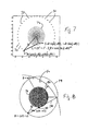
- the geometry of an embodiment of a third generation, four-slice system is shown schematically in Figure 3 .
- Gantry 12 rotates about a z -axis 50.
- Detector 18 surface 52 lies on a cylinder, with four rows, each having 888 detector elements 20.
- Row data represent rays 54 that do not lie in horizontal reconstruction planes.
- a "cone angle" 56 with respect to a gantry plane (which itself is defined as a plane orthogonal to a z-axis that contains the source 14 point and bisects the detector 18 cylinder) represents a degree of inconsistency in cone beam data as compared to two-dimensional CT data. Planes containing a focal spot or point 58 intersect detector surface 52 along arcs 60 that drop off as cos( ⁇ ).
- a ray 62 that passes through voxel V1 hits detector array 18, so that data representing voxel V1 is estimated by interpolation.
- a ray 64 through voxel V2 does not hit detector array 18, so data representing voxel V2 is estimated by extrapolation.
- a compromise is effected between improved image quality and practicality by combining voxel-driven back-projection, data extrapolation, and weighting methods, such as half-scan, underscan, and overscan, to handle data redundancy conditions and smooth out discontinuities at the 0, 2 ⁇ source angle interface for helical trajectories.
- Use of extrapolation allows high scanning pitches to be used by providing a constant number of projection measurements for all voxels for a given source position and by ensuring that no measurement is discarded. Extrapolation thus eliminates cone-angle and detector size-related variable voxel sampling of source positions.
- Source-related data redundancies and associated vanishing weights are used to manage data inconsistencies resulting from the combination of cone-angle and helical scanning.
- HS and HQ pitches are calculated such that at least one ray or two rays, respectively, contribute to a given voxel.
- a Feldkamp (FDK) reconstruction algorithm is modified for use in third-generation multi-slice CT imaging systems.
- FDK is a perturbation of 2-dimensional filtered back-projection (FBP), which calculates a double integral over a fan angle, ⁇ , and a source angle, ⁇ , for each point in a reconstructed image.
- FBP 2-dimensional filtered back-projection
- a contribution of each infinitesimal segment along a source trajectory to a voxel in a reconstruction volume is computed as if the segment were contributing to the 2-dimensional reconstruction in a plane defined by the infinitesimal segment and the point/voxel. Therefore, FDK is derived from 2-dimensional FBP by a change of variables.
- S is a source 14 to isocenter 82 distance;
- S + D is a source 14 to detector 18 distance;
- ⁇ is a source angle, ⁇ t is a source angle in a tilted plane;
- ⁇ is a fan angle;
- ⁇ t is a fan angle in the tilted plane; and
- ⁇ is an angle between a horizontal and a tilted plane.
- r is a radial vector
- r t is a radial vector in the tilted plane under consideration (i.e., tilted with respect to the gantry plane.)
- Embodiments in which flat panel x-ray detectors are used do not require interpolation onto cos( ⁇ ) arcs; i.e., filtering along detector rows is equivalent to filtering co-planar data for such panels. Therefore, the changes of variables differ somewhat in embodiments using a flat panel x-ray detector.
- Plugging (1) and (2) into the 2-dimensional FBP reconstruction formula thus results in an embodiment that exactly implements FDK on a third generation CT imaging system.
- a shift-invariant approximation to a shift-variant kernel (written omitting the superscript t) is written: sin ⁇ ⁇ - ⁇ ⁇ ⁇ ⁇ ⁇ ⁇ ⁇ ⁇ ⁇ ⁇ ⁇ ⁇ 0 ⁇ ⁇ ⁇ ⁇ - ⁇ ⁇ 1 / 2 ⁇ sin ⁇ ⁇ ⁇ - ⁇ ⁇ .
- x-ray source 14 is moved through a trajectory, and a cone beam 16 is projected from x-ray source 14 through an object or patient 22 towards curved detector 18.
- a signal representative of detected x-rays 16 passing through object 22 is processed by imaging system 10, for example, by DAS 32, imaging reconstructor 34, and computer 36, to produce a tomographic image that appears on CRT display 42.
- imaging system 10 for example, by DAS 32, imaging reconstructor 34, and computer 36
- the processing of the signal in accordance with equation 9 comprises applying half scan weights to pre-processed data, prior to reconstruction filtering. These weights account for the fact that several line integrals have been measured twice, while most have been measured only once.
- reconstruction filtering is performed, as represented by the convolution of g and p ⁇ HSW in equation 9.
- back-projection is applied in three-dimensional space, with compensation for x-ray cone beam geometry, by summing contributions from each projection to a given pixel. This back-projection is represented by the integral sum in equation 9.
- a derivation of one embodiment of an FDK algorithm of the present invention approximating FDK for third generation CT imaging systems 10 without cos( ⁇ ) detector interpolation involves two approximations. The approximations are first, that the cone angle is small, so that convolution filtering is possible, and second, that the data are filtered along detector rows (i.e., without interpolation along cos( ⁇ ) arcs).
- Figure 5 is a geometric representation of fan-beam geometry. All angles and distances refer to a central plane of gantry 12, orthogonal to a z -axis. A voxel M is shown projected onto the gantry 12 central plane.
- E t 2 [ E 2 + ⁇ ' 2 ], where ⁇ is measured on detector 18.
- the source to detector distance (as measured on a ray through the z-axis), is changed from E to E t written as:
- E t 2 [ E 2 + ⁇ ' 2 ], where ⁇ ' is measured on the detector.
- Figure 6 is a geometric representation of a third-generation, cone-beam geometry with a cylindrical detector 18.
- a ray 66 with a cone-angle ⁇ with respect to a plane of gantry 12 is shown, the plane being defined by O, x , and y in Figure 6 .
- an associated ray 68 (for the same elevation on detector 18) passing through an axis of rotation z .
- B denotes the overscan angle
- SW( ⁇ , ⁇ ) denotes a weight function that is either an overscan weight function or an underscan weight function
- x-ray source 14 is moved through a trajectory.
- a cone beam 16 is projected from x-ray source 14 through an object or patient 22 towards curved detector 18.
- a signal representative of detected x-rays 16 passing through object 22 is processed by imaging system 10 by, for example, DAS 32, imaging reconstructor 34, and computer 32, to produce a tomographic image that is displayed on CRT display 42.
- the processing of the signal in accordance with equation (16), when SW( ⁇ , ⁇ ) is an underscan weighting function, comprises weighting, filtering, and back-projecting the data, in that order. Back-projection is performed in three-dimensional space, with compensation for x-ray cone beam geometry.
- SW( ⁇ , ⁇ ) is an overscan weighting function
- the weights depend only upon a source angle.
- the weights account for the fact that projection data have been acquired over a range of source angles larger than 2 ⁇ , and accordingly, several line integrals have been measured three times.
- filtering is performed before weighting, and weighting is performed before back-projecting.
- an FDK algorithm is adapted to helical trajectories.
- most imaging is helical.
- Helical scanning is possible by using a modification in which all z distances are calculated with respect to a gantry central plane.
- appropriate attention must be given to obtaining an appropriate number of data samples for each voxel in the reconstructed image and handling of data redundancy.
- Providing at least two samples from the detector using only interpolation leads to very slow pitch and 2 to 3 samples per voxel; on the other hand, handling sampling discrepancy by simply throwing away a third sample is not acceptable from a patient dose standpoint. Therefore, in one embodiment, extrapolation is used to enable faster pitches while taking into account all projection samples.
- Standard weighting techniques are used to handle data redundancy. Specifically, a HQ mode utilizing this embodiment accounts for two or more samples per voxel. Data redundancy from a third sample is handled by employing overscan or underscan weights to smooth away data discrepancies resulting from the helical trajectory. In an HS mode embodiment, one or two samples per voxel are used. Data redundancies associated with the second sample are handled using half-scan weights to feather data inconsistencies resulting from the helical trajectory and cone-angle.
- a 7:1 pitch is used to provide a best cone-artifact abatement measure.
- a modified FDK algorithm given by equation (15) is used with an additional modification making the gantry plane source-angle dependent.
- the back-projection was extended from 2 ⁇ to (8/7+ ⁇ ) ⁇ 2 ⁇ using overscan weights, where ⁇ is a parameter of the method.
- overscan weights avoids data inconsistencies of helical algorithm implementations at source angles 0 and 2 ⁇ relating to a z -motion of the patient with respect to the source.
- ⁇ where x varies between 0 and 1 in the interval considered, and ⁇ is a parameter.
- high pitch reconstructions are implemented by applying 1 ⁇ 2 scan weights to the modified FDK algorithm described above, equation (8).
- the data are back-projected on a three-dimensional Cartesian grid.
- x-ray source 14 is moved through a helical trajectory relative to object 22.
- An x-ray cone beam 16 is projected from source 14 through object 22 to a curved, cylindrical detector 18.
- Processing of detector data to produce CT images in imaging system 10 is provided by DAS 32, imaging reconstructor 34, and computer 36, for example, and an image is displayed on CRT display 42.
- This processing includes determining contributions of segments along the trajectory to voxels in a reconstruction volume of the object, including compensating the determined contributions for curvature of the detector and x-ray cone beam geometry. This determination comprises filtering and back-projecting using a double integral over a fan angle and source angle for each point in the reconstruction volume.
- FIG. 7 Referring to the graphical representation of a polar reconstruction lattice shown in Figure 7 , an exemplary embodiment of the present invention was implemented using a reconstruction done on a polar lattice using MATLAB.
- the dimensions of the axes of Figure 7 are in cm. for the exemplary embodiment.
- Forty-one of 984 source positions 70 are shown.
- An undersampled reconstruction lattice 72 is also shown.
- the image was interpolated onto a Cartesian lattice using MATLAB's cubic interpolation call.
- a polar lattice is an appropriate geometry for a third generation system having a circular source trajectory.
- R is a source trajectory radius and kd ⁇ represents a source angle.
- a pixel under consideration is at a radial distance r and an angle jd ⁇ .
- L a source-pixel distance.
- Pre-computation significantly reduced the algorithm's floating point operation (FLOP) count, and efficiency could also be improved by avoiding back-projection onto every lattice point near the origin. (Selective back-projection onto some points in the polar lattice increases the programming burden.)
- FLOP floating point operation
- FIG. 8 Referring to the geometric representation of third generation and source trajectory shown in Figure 8 , 0 th order extrapolation was used when the required data in the voxel-driven back-projection fell above or below the 8-slice detector. First order or higher order, or non-polynomial methods, might be used for the extrapolation.
- a source trajectory 74 and detector surface 52 are shown.
- a region of reconstruction is shown at 76.
- Half-scan data was collected only between view angles -( ⁇ /2 + ⁇ ) and +( ⁇ /2 + ⁇ ).
- a ray 78 through a point 80 at view angle -( ⁇ /2 + ⁇ ) does not hit detector 18 surface 52 for helical pitches above N slices /2, and hence, data for ray 78 is extrapolated.
- embodiments of the invention are applicable to 8, 16, or other numbers of detector rows.
- embodiments described herein use detector row-to-row interpolation for a given source position.
- further improvement in image quality at small cone angles can be obtained, with somewhat increased implementation complexity, by using conjugate ray interpolation/extrapolation to zero-cone angle.
- the CT system described herein is a "third generation" system in which both the x-ray source and detector rotate with the gantry.
- CT systems including "fourth generation" systems wherein the detector is a full-ring stationary detector and only the x-ray source rotates with the gantry, may be used if individual detector elements are corrected to provide substantially uniform responses to a given x-ray beam.
Description
- This invention relates generally to methods and apparatus for reconstruction of imaging data, and more particularly to cone beam correction for reconstruction of three-dimensional computed tomography imaging data.
- In at least one known computed tomography (CT) imaging system configuration, an x-ray source projects a fan-shaped beam which is collimated to lie within an X-Y plane of a Cartesian coordinate system and generally referred to as the "imaging plane". The x-ray beam passes through the object being imaged, such as a patient. The beam, after being attenuated by the object, impinges upon an array of radiation detectors. The intensity of the attenuated beam radiation received at the detector array is dependent upon the attenuation of the x-ray beam by the object. Each detector element of the array produces a separate electrical signal that is a measurement of the beam attenuation at the detector location. The attenuation measurements from all the detectors are acquired separately to produce a transmission profile.
- In known third generation CT systems, the x-ray source and the detector array are rotated with a gantry within the imaging plane and around the object to be imaged so that the angle at which the x-ray beam intersects the object constantly changes. A group of x-ray attenuation measurements, i.e., projection data, from the detector array at one gantry angle is referred to as a "view". A "scan" of the object comprises a set of views made at different gantry angles, or view angles, during one revolution of the x-ray source and detector. In an axial scan, the projection data is processed to construct an image that corresponds to a two dimensional slice taken through the object. One method for reconstructing an image from a set of projection data is referred to in the art as the filtered back-projection technique. This process converts the attenuation measurements from a scan into integers called "CT numbers" or "Hounsfield units", which are used to control the brightness of a corresponding pixel on a cathode ray tube display.
- In at least one known multi-slice CT system, a "cone angle," or volumetric content of measured data, is very small. Therefore, this system currently processes 3-dimensional data using a 2-dimensional algorithm. By using the Feldkamp (FDK) algorithm, which is a simple perturbation of a 2-dimensional filtered back projection (FBP) algorithm for image reconstruction, excellent image quality is obtained for these relatively small cone angles. The FDK algorithm is not exact, however, and as the number of slices increases (for fixed slice thickness) cone angle and cone beam artifacts increase.
- It would be desirable to extend 2-dimensional CT fan-beam reconstruction algorithms to the cone-beam geometry of a third-generation multi-slice CT imaging system. Such a reconstruction could be based upon a modified FDK algorithm, but the modifications would have to compensate for both a cylindrical (rather than planar) area detector, and a helical (rather than circular) source trajectory. Use of a curved detector array requires data interpolation along curved lines on the detector, the application of a new data filter, and of pre- and post-convolution weights. However, the helical source trajectory complicates voxel-driven back projection in that variable data (projection ray) redundancy conditions are encountered across a reconstructed image. For each voxel in a reconstruction volume, it is necessary to compute, for each source position, a ray passing from the x-ray source through the voxel. Thus, approaches must be found to address the handling of data redundancy and handling the variable number of rays that contribute to voxels.
- Two approaches to addressing the problems of data redundancy and the variable number of rays contributing to voxels are known. In one approach, the helical pitch is limited so that at least two (interpolated) samples are obtained for each voxel. Extra data is thrown away, retaining only 2π worth of projections. The z-resolution available from conjugate rays is ignored to keep the approach simple. However, in patient scanning, this approach is impractical, because it severely limits patient coverage and results in increases radiation dose. A second approach improves on the first by providing better image quality (IQ) and reduced patient dose, while handling any practical pitch. However, a method implementing this approach to handling the above-mentioned problems requires that all data passing through a given voxel (for given source and fan angles) are simultaneously available. As a result, methods based on the second approach are impractical to implement.
- In
US-A-5 430 783 an x-ray computed tomography system for helically scanning a patient translates the patient as projections of the patient at various beam angles are obtained. A cone beam reconstruction method, which accounts for the divergence of the rays of a fan beam of x-rays, is used to reconstruct multiple narrow slices which are combined to provide a larger slice with an improved slice profile. - In "A general cone-beam reconstruction algorithm" by Wang G., Lin T-H., Cheng P. and Shinozaki D. M., IEEE Transactions on Medical Imaging 1993, a modification of the cone-beam reconstruction method of Feldkamp is disclosed which takes the change of the source angle β and source angle differential dβ in the fan beam planes which are tilted with respect to the (not tilted) mid-plane into account (D4: p.488).
- It would therefore be desirable to provide methods and apparatus that provide acceptable compromises between improved image quality and practicality in third generation CT imaging systems.
- According to a first aspect of the invention, there is provided a method for multi-slice, computed tomography imaging, said method comprising: A method for multi-slice, computed tomographic imaging, the method comprising: moving an x-ray source through a trajectory; projecting an x-ray cone beam from the moving x-ray source through an object towards a curved detector; and weighting, filtering, and back-projecting a signal representative of detected x-rays passing through the object to produce a tomographic image. The back-projection is performed in a three-dimensional space, with compensation for x-ray cone-beam geometry. The weighting, filtering, and back-projecting comprises determining a reconstruction image function f (v) written as:

where ⊗ represents convolution; Γ is a maximum fan angle of the fan beam; S is a source to isocenter distance; v is a voxel with cylindrical coordinates (r, ϕ,κ); ξ' =ξ' (v,β) is a z-elevation for a projection of v onto a detector; L is a voxel to source distance (in three-dimensional space); g() denotes a fan-beam reconstruction convolution kernel; p* is data that has been interpolated onto a tilted plane; HSW denotes the half-scan weights; - γ gamma is a fan angle;
- β is a source angle;
- α is an angle between a horizontal plane and the tilted planes.
- According to a second aspect of the invention, there is provided a multi-slice, computed tomography CT imaging system, the imaging system comprising a moveable x-ray source and a curved detector, the system being configured to:
- move an x-ray source through a trajectory; project an x-ray cone beam from the moving x-ray source through an object towards a curved detector; and
- weight, filter, and back-project a signal representative of detected x-rays passing through the object to produce a tomographic image. The system is configured to back-project in a three-dimensional space, with compensation for x-ray cone-beam geometry. The system is further configured to determine a reconstruction image function written as:

- γ gamma is a fan angle;
- β is a source angle;
- α is an angle between a horizontal plane and the tilted planes.
- The above described embodiment and others described in detail herein provide improved image quality in third generation CT imaging systems, even for cylindrical detectors and helical source trajectories. In addition, these embodiments can be implemented within the practicality constraints imposed by CT imaging hardware and patient dosage limitations.
- The invention will now be described in greater detail, by way of example, with reference to the drawings, in which:-
-
Figure 1 is a pictorial view of a CT imaging system. -
Figure 2 is a block schematic diagram of the system illustrated inFigure 1 . -
Figure 3 is a geometric representation of an embodiment of a third generation, four slice CT imaging system. -
Figure 4 is a geometric diagram showing conversion of FDK infinitesimals into third generation geometry. -
Figure 5 is a geometric representation of fan beam geometry. -
Figure 6 is a geometric representation of a third generation, cone-beam geometry with a cylindrical detector. -
Figure 7 is a graphical representation of a polar reconstruction lattice. -
Figure 8 is a geometric representation of a third generation geometry and source trajectory. - Referring to
Figures 1 and 2 , a computed tomograph (CT)imaging system 10 is shown as including agantry 12 representative of a "third generation" CT scanner. Gantry 12 has anx-ray source 14 that projects a beam ofx-rays 16 toward adetector array 18 on the opposite side ofgantry 12.Detector array 18 is formed bydetector elements 20 which together sense the projected x-rays that pass through anobject 22, for example a medical patient.Detector array 18 may be fabricated in a single slice or multi-slice configuration. Eachdetector element 20 produces an electrical signal that represents the intensity of an impinging x-ray beam and hence the attenuation of the beam as it passes throughpatient 22. During a scan to acquire x-ray projection data,gantry 12 and the components mounted thereon rotate about a center ofrotation 24. - Rotation of
gantry 12 and the operation ofx-ray source 14 are governed by acontrol mechanism 26 ofCT system 10.Control mechanism 26 includes anx-ray controller 28 that provides power and timing signals to x-raysource 14 and agantry motor controller 30 that controls the rotational speed and position ofgantry 12. A data acquisition system (DAS) 32 incontrol mechanism 26 samples analog data fromdetector elements 20 and converts the data to digital signals for subsequent processing. Animage reconstructor 34 receives sampled and digitized x-ray data fromDAS 32 and performs high speed image reconstruction. The reconstructed image is applied as an input to acomputer 36 which stores the image in amass storage device 38. -
Computer 36 also receives commands and scanning parameters from an operator viaconsole 40 that has a keyboard. An associated cathoderay tube display 42 allows the operator to observe the reconstructed image and other data fromcomputer 36. The operator supplied commands and parameters are used bycomputer 36 to provide control signals and information toDAS 32,x-ray controller 28 andgantry motor controller 30. In addition,computer 36 operates atable motor controller 44 which controls a motorized table 46 to positionpatient 22 ingantry 12. Particularly, table 46 moves portions ofpatient 22 throughgantry opening 48. - In one embodiment of the present invention, a 2-dimensional CT fan-beam reconstruction method is extended to a cone-beam geometry on a third generation multi-slice CT. A curved, cylindrical detector is used rather than a planar area detector, as is a helical, rather than a circular, source trajectory. The curved detector array produces data that is interpolated along curved lines of the detector by subsequent processing, and a data filter is used to filter the interpolated data using pre- and post-convolution weights. The helical source trajectory produces variable data (projection ray) redundancy conditions across the reconstructed image of the voxel-driven back-projection. Therefore, for each view in the reconstruction volume, a ray passing from the x-ray source through each voxel is computed. The geometry of an embodiment of a third generation, four-slice system is shown schematically in
Figure 3 .Gantry 12 rotates about a z-axis 50.Detector 18surface 52 lies on a cylinder, with four rows, each having 888detector elements 20. Row data representrays 54 that do not lie in horizontal reconstruction planes. A "cone angle" 56 with respect to a gantry plane (which itself is defined as a plane orthogonal to a z-axis that contains thesource 14 point and bisects thedetector 18 cylinder) represents a degree of inconsistency in cone beam data as compared to two-dimensional CT data. Planes containing a focal spot orpoint 58 intersectdetector surface 52 alongarcs 60 that drop off as cos(γ). Aray 62 that passes through voxel V1 hitsdetector array 18, so that data representing voxel V1 is estimated by interpolation. Aray 64 through voxel V2, however, does not hitdetector array 18, so data representing voxel V2 is estimated by extrapolation. - In one embodiment, a compromise is effected between improved image quality and practicality by combining voxel-driven back-projection, data extrapolation, and weighting methods, such as half-scan, underscan, and overscan, to handle data redundancy conditions and smooth out discontinuities at the 0, 2π source angle interface for helical trajectories. Use of extrapolation allows high scanning pitches to be used by providing a constant number of projection measurements for all voxels for a given source position and by ensuring that no measurement is discarded. Extrapolation thus eliminates cone-angle and detector size-related variable voxel sampling of source positions. Source-related data redundancies and associated vanishing weights (half-scan weights in high speed (HS) pitches, overscan or underscan in high quality (HQ) pitches) are used to manage data inconsistencies resulting from the combination of cone-angle and helical scanning. To enable independent projection processing, HS and HQ pitches are calculated such that at least one ray or two rays, respectively, contribute to a given voxel.
- In one embodiment, a Feldkamp (FDK) reconstruction algorithm is modified for use in third-generation multi-slice CT imaging systems. FDK is a perturbation of 2-dimensional filtered back-projection (FBP), which calculates a double integral over a fan angle, γ, and a source angle, β, for each point in a reconstructed image. In FDK, a contribution of each infinitesimal segment along a source trajectory to a voxel in a reconstruction volume is computed as if the segment were contributing to the 2-dimensional reconstruction in a plane defined by the infinitesimal segment and the point/voxel. Therefore, FDK is derived from 2-dimensional FBP by a change of variables. Referring to
Figure 4 and voxel V, S is asource 14 to isocenter 82 distance; S + D is asource 14 todetector 18 distance; β is a source angle, β t is a source angle in a tilted plane; γ is a fan angle; γ t is a fan angle in the tilted plane; and α is an angle between a horizontal and a tilted plane.r is a radial vector, andr t is a radial vector in the tilted plane under consideration (i.e., tilted with respect to the gantry plane.) Embodiments in which flat panel x-ray detectors are used do not require interpolation onto cos(γ) arcs; i.e., filtering along detector rows is equivalent to filtering co-planar data for such panels. Therefore, the changes of variables differ somewhat in embodiments using a flat panel x-ray detector. - After interpolating projection data onto planar sets, projection rays are distributed within the fan according to a fan-beam parameterization written as:

where γt represents the fan angle in the tilted plane, and dβt represents the infinitesimal arc length in the tilted plane indicated byr t as shown inFigure 4 . - Thus,

- Plugging (1) and (2) into the 2-dimensional FBP reconstruction formula thus results in an embodiment that exactly implements FDK on a third generation CT imaging system.
- An approximation leads to an embodiment of a shift-invariant filter that very closely approximates the true, shift-variant filter, but which is simpler and more readily accommodates convolution in the Fourier domain. One embodiment of a reconstruction algorithm of the present invention utilizing an exact shift-variant filter for FDK and its shift-invariant approximation is described as follows.
- A third-generation FDK fan-beam parameterization in tilted planes is given by (3):

- A shift-invariant approximation to a shift-variant kernel (written omitting the superscript t) is written:

- Accordingly, the following equation is written by substituting for η in equation (4) above:

where h() is a parallel kernel and A, B, and K are written as:

- The kernel terms that multiply the expression for the parallel kernel h are written as:

- By replacing the shift-variant kernel g by the shift-invariant approximation above into equation (8), an exact third-generation FDK algorithm embodiment is obtained.
- In another embodiment useful for small cone-angles, such as those associated with current multi-slice scanners, an approximation that directly renders the filtering shift-invariant (and therefore enables convolution) is utilized. This embodiment is useful for high speed mode. For small angles, the convolution is simplified by approximating fan-beam parameterization by:

where α = α(v, β). The reconstruction algorithm is then written as:

where:
⊗ represents convolution;
Γ is a maximum fan angle of the fan beam;
S is a source to isocenter distance;
v is a voxel with cylindrical coordinates (r, ϕ,κ);
ξ' =ξ' (v,β) is a z-elevation for a projection of v onto a detector;
L is a voxel to source distance (in three-dimensional space);
g() denotes a fan-beam reconstruction convolution kernel;
P * is data that has been interpolated onto a tilted plane; and
HSW denotes the half-scan weights. - To process image data in accordance with equation (9),
x-ray source 14 is moved through a trajectory, and acone beam 16 is projected from x-ray
source 14 through an object orpatient 22 towardscurved detector 18. A signal representative of detectedx-rays 16 passing throughobject 22 is processed byimaging system 10, for example, byDAS 32, imaging
reconstructor 34, andcomputer 36, to produce a tomographic image that appears onCRT display 42. (As used herein, the "signal representative of detected x-rays" is intended to be broadly construed. For example, embodiments in which parallel data lines fordetector elements 20 are used to transmit the signal fromdetector 18 toDAS 32 are intended to be included, as are embodiments which multiplex data on a single line.) The processing of the signal in accordance with equation 9 comprises applying half scan weights to pre-processed data, prior to reconstruction filtering. These weights account for the fact that several line integrals have been measured twice, while most have been measured only once. Next, reconstruction filtering is performed, as represented by the convolution of g and p×HSW in equation 9. Next, back-projection is applied in three-dimensional space, with compensation for x-ray cone beam geometry, by summing contributions from each projection to a given pixel. This back-projection is represented by the integral sum in equation 9. - In an embodiment useful for high quality modes, interpolation of projection data along cos(γ) arcs is eliminated. Accordingly, projection data are filtered along detector rows. The parameterization approximation (8) is retained.
- A derivation of one embodiment of an FDK algorithm of the present invention approximating FDK for third generation
CT imaging systems 10 without cos(γ) detector interpolation involves two approximations. The approximations are first, that the cone angle is small, so that convolution filtering is possible, and second, that the data are filtered along detector rows (i.e., without interpolation along cos(γ) arcs).Figure 5 is a geometric representation of fan-beam geometry. All angles and distances refer to a central plane ofgantry 12, orthogonal to a z-axis. A voxel M is shown projected onto thegantry 12 central plane. Considering reconstruction of voxel M with amulti-slice detector 18, a change of geometry from fan-beam to cone-beam results in a source to isocenter distance S changing into a source to z-axis St given by: St = [S 2 + ξ2]1/2, where ξ is measured on the z-axis, and the source to detector distance E = S + D (as measured on a ray through the z-axis) is changed into Et , given by: - E t2 = [E 2 + ξ'2], where ξ is measured on
detector 18. - Starting from a 2D reconstruction equation for fan-beam data, and in the notation of
Figure 5 :
with:

- Using a multi-slice detector, the geometry changes from fan-beam to cone-beam in reconstruction of a voxel M. As a result, a source to isocenter distance S is changed into the source to z-axis distance St written as:
- St = [S 2 + ξ2]1/2, where ξ is measured on the z-axis.
- Also, the source to detector distance (as measured on a ray through the z-axis), is changed from E to Et written as:
- E t
2 = [E 2 + ξ'2], where ξ' is measured on the detector. -
Figure 6 is a geometric representation of a third-generation, cone-beam geometry with acylindrical detector 18. Aray 66 with a cone-angle α with respect to a plane ofgantry 12 is shown, the plane being defined by O, x, and y inFigure 6 . Also shown is an associated ray 68 (for the same elevation on
detector 18) passing through an axis of rotation z. A rotation angle dβ t such that a small rotation dβ around z is equivalent to dβ t around r is written as:
- A fan-angle γ in a plane of the gantry (orthogonal to z) is now replaced by a fan-angle γ t in a tilted surface:

- Accordingly:

- Voxel-dependent geometric weight factor is determined. As data are filtered along detector rows, for a given voxel M, an associated ξ to be used in the calculation of dβ' above is found. Givenκ, and
 ξ', it is thus written:

- Putting all the terms together, an equation for a third-generation FDK reconstruction algorithm is written:

- Alternatively, an equation for an embodiment of a modified FDK algorithm is written as:


where B denotes the overscan angle, and SW(β,γ) denotes a weight function that is either an overscan weight function or an underscan weight function. (For underscan, B=0). - To process image data in accordance with equation (16),
x-ray source 14 is moved through a trajectory. Acone beam 16 is projected fromx-ray source 14 through an object orpatient 22 towardscurved detector 18. A signal representative of detectedx-rays 16 passing throughobject 22 is processed byimaging system 10 by, for example,DAS 32,imaging reconstructor 34, andcomputer 32, to produce a tomographic image that is displayed onCRT display 42. The processing of the signal in accordance with equation (16), when SW(β,γ) is an underscan weighting function, comprises weighting, filtering, and back-projecting the data, in that order. Back-projection is performed in three-dimensional space, with compensation for x-ray cone beam geometry. When SW(β,γ) is an overscan weighting function, the weights depend only upon a source angle. In this case, the weights account for the fact that projection data have been acquired over a range of source angles larger than 2π, and accordingly, several line integrals have been measured three times. Thus, filtering is performed before weighting, and weighting is performed before back-projecting. - In one embodiment, an FDK algorithm is adapted to helical trajectories. In known multi-slice CT systems, most imaging is helical. Helical scanning is possible by using a modification in which all z distances are calculated with respect to a gantry central plane. However, appropriate attention must be given to obtaining an appropriate number of data samples for each voxel in the reconstructed image and handling of data redundancy. Providing at least two samples from the detector using only interpolation leads to very slow pitch and 2 to 3 samples per voxel; on the other hand, handling sampling discrepancy by simply throwing away a third sample is not acceptable from a patient dose standpoint. Therefore, in one embodiment, extrapolation is used to enable faster pitches while taking into account all projection samples. Standard weighting techniques are used to handle data redundancy. Specifically, a HQ mode utilizing this embodiment accounts for two or more samples per voxel. Data redundancy from a third sample is handled by employing overscan or underscan weights to smooth away data discrepancies resulting from the helical trajectory. In an HS mode embodiment, one or two samples per voxel are used. Data redundancies associated with the second sample are handled using half-scan weights to feather data inconsistencies resulting from the helical trajectory and cone-angle.
- In one embodiment, for an eight-slice system, a 7:1 pitch is used to provide a best cone-artifact abatement measure. A modified FDK algorithm given by equation (15) is used with an additional modification making the gantry plane source-angle dependent. Also, the back-projection was extended from 2π to (8/7+ε)×2π using overscan weights, where ε is a parameter of the method.
The use of overscan weights avoids data inconsistencies of helical algorithm implementations at source angles 0 and 2π relating to a z-motion of the patient with respect to the source. (Imaging without handling this inconsistency results in streak artifacts in a direction of the source position at angle 0.) Useful overscan functions include those written as: f(x) = 3x 2 - 2x 3, where x varies between 0 and 1 in the interval considered;

- In one embodiment, high pitch reconstructions are implemented by applying ½ scan weights to the modified FDK algorithm described above, equation (8). In another embodiment, the data are back-projected on a three-dimensional Cartesian grid.
- In one embodiment of the present invention,
x-ray source 14 is moved through a helical trajectory relative to object 22. Anx-ray cone beam 16 is projected fromsource 14 throughobject 22 to a curved,cylindrical detector 18. Processing of detector data to produce CT images inimaging system 10 is provided byDAS 32,imaging reconstructor 34, andcomputer 36, for example, and an image is displayed onCRT display 42. This processing includes determining contributions of segments along the trajectory to voxels in a reconstruction volume of the object, including compensating the determined contributions for curvature of the detector and x-ray cone beam geometry. This determination comprises filtering and back-projecting using a double integral over a fan angle and source angle for each point in the reconstruction volume. - Referring to the graphical representation of a polar reconstruction lattice shown in
Figure 7 , an exemplary embodiment of the present invention was implemented using a reconstruction done on a polar lattice using MATLAB. The dimensions of the axes ofFigure 7 are in cm. for the exemplary embodiment. Forty-one of 984 source positions 70 are shown. Anundersampled reconstruction lattice 72 is also shown. The image was interpolated onto a Cartesian lattice using MATLAB's cubic interpolation call. A polar lattice is an appropriate geometry for a third generation system having a circular source trajectory. An angular lattice increment equal to the angular increment ofCT scanner 10 between views was selected, dθ = dβ = 2π/Nviews, so that dr∼dx, where dx is the size of a pixel of the final image.
Thus, a distance between reconstruction lattice points is roughly dx at outer edges of the FOV, decreasing to zero at the center. The polar lattice simplified programming, and further permitted precomputation of all trigonometric functions used in the back-projection. - In
Figure 7 , R is a source trajectory radius and kdθ represents a source angle. A pixel under consideration is at a radial distance r and an angle jdθ. With this in mind, it is relatively simple to compute L, a source-pixel distance. The only trigonometric functions needed to calculate these distances L are {cos(i dθ)} for i=0, ... (number of views - 1). An extension to a 3d back-projection is also simple, and is given by L 3d =(L 2+dz 2)1/2. Pre-computation significantly reduced the algorithm's floating point operation (FLOP) count, and efficiency could also be improved by avoiding back-projection onto every lattice point near the origin. (Selective back-projection onto some points in the polar lattice increases the programming burden.) Referring to the geometric representation of third generation and source trajectory shown inFigure 8 , 0th order extrapolation was used when the required data in the voxel-driven back-projection fell above or below the 8-slice detector. First order or higher order, or non-polynomial methods, might be used for the extrapolation. Asource trajectory 74 anddetector surface 52 are shown. A region of reconstruction is shown at 76. Half-scan data was collected only between view angles -(π/2 + Γ) and +(π/2 + Γ). Aray 78 through apoint 80 at view angle -(π/2 + Γ) does not hitdetector 18surface 52 for helical pitches above N slices/2, and hence, data forray 78 is extrapolated. However, aconjugate ray 82, collected a view angle 0, is always measured bydetector 18 with cone angle = 0. In one embodiment illustrated inFigure 8 , R = 54.1 cm; D = 40.8 cm; FOV = 48 cm; Γ = 27.4°; z source = pitch × slice width × (π/2 + γ)/(2π); and κ = ray height on detector = -z source × (R + D)/L ∼ 1.06 × pitch × slice width. - From the preceding description of various embodiments of the present invention, it is evident that the embodiments described herein lead to simple changes in data processing that makes reconstruction more robust to large cone angles. Data are filtered "on the fly," with only minor changes to standard reconstruction chains. The embodiments described herein should be contrasted with previously known adaptations of the FDK algorithm to third-generation CT with cylindrical detectors that fail to account for geometry and thus filter non-coplanar data. In addition, the embodiments described herein do not require simultaneous data availability for all rays passing through a
voxel for a given 2D Radon point as does at least one other known reconstruction method. The embodiments described herein also fully use patient dose while providing increased patient coverage. Artifacts are effectively eliminated by the use of over-scan weights or underscan weights (respectively half-scan weights), which, in combination with the use of extrapolation, makes the use of high pitches practical in all imaging modes without wasting patient dose. The embodiments described herein use relatively few views as compared to at least one previously known four slice helical reconstruction algorithm, and accordingly lead to fast reconstruction and improved temporal resolution. It will be recognized by those skilled in the art that the method and apparatus embodiments of the present invention described herein provide acceptable compromises between improved image quality and practicality in third generation CT imaging systems. Moreover, these embodiments can be implemented within the practicality constraints imposed by CT imaging hardware and patient dosage limitations. - Although particular embodiments of the invention have been described and illustrated in detail, it is to be clearly understood that the same is intended by way of illustration and example only and is not to be taken by way of limitation. For example, embodiments of the invention are applicable to 8, 16, or other numbers of detector rows. Also, the embodiments described herein use detector row-to-row interpolation for a given source position. However, further improvement in image quality at small cone angles can be obtained, with somewhat increased implementation complexity, by using conjugate ray interpolation/extrapolation to zero-cone angle. In addition, the CT system described herein is a "third generation" system in which both the x-ray source and detector rotate with the gantry. Many other CT systems including "fourth generation" systems wherein the detector is a full-ring stationary detector and only the x-ray source rotates with the gantry, may be used if individual detector elements are corrected to provide substantially uniform responses to a given x-ray beam.
Claims (5)
- A method for multi-slice, computed tomographic imaging, said method comprising:moving an x-ray source (14) through a trajectory (74);projecting an x-ray cone beam (16) from the moving x-ray source through an object towards a curved detector (20); andweighting, filtering, and back-projecting a signal representative of detected x-rays passing through the object to produce a tomographic image;the back-projection being performed in a three-dimensional space, with compensation for x-ray cone-beam geometry.characterized in that:said weighting, filtering, and back-projecting comprises determining a reconstruction image function f (v) written as:where

⊗ represents convolution;
Γ is a maximum fan angle of the fan beam;
S is a source to isocenter distance;
v is a voxel with cylindrical coordinates (r, ϕ,κ);
ξ' =ξ' (v,β) is a z-elevation for a projection of v onto a detector;
L is a voxel to source distance (in three-dimensional space);
g() denotes a fan-beam reconstruction convolution kernel;
p * is data that has been interpolated onto a tilted plane; and
HSW denotes the half-scan weights;
γ gamma is a fan angle;
β is a source angle;
α is an angle between a horizontal plane and the tilted planes.; - A method in accordance with Claim 1 wherein back-projecting using a signal representative of detected x-rays comprises the step of back-projecting onto a polar reconstruction lattice (72).
- A method in accordance with Claim 1 or 2, wherein said weighting is performed prior to said filtering, and said filtering is performed prior to said back-projection.
- A multi-slice, computed tomography CT imaging system (10), said imaging system comprising a moveable x-ray source (14) and a curved detector (20), said system being configured to:move an x-ray source through a trajectory (74);project an x-ray cone beam (16) from said moving x-ray source through an object towards a curved detector; andweight, filter, and back-project a signal representative of detected x-rays passing through the object to produce a tomographic image;said system being configured to back-project in a three-dimensional space, with compensation for x-ray cone-beam geometry;characterized by:said system being configured to determine a reconstruction image function written as:where

⊗ represents convolution;
Γ is a maximum fan angle of the fan beam;
S is a source to isocenter distance;
v is a voxel with cylindrical coordinates (r, (ϕ,κ);
ξ' =ξ' (v,β) is a z-elevation for a projection of v onto a detector;
L is a voxel to source distance (in three-dimensional space);
g() denotes a fan-beam reconstruction convolution kernel;
p * is data that has been interpolated onto a tilted plane; and
HSW denotes the half-scan weights;
γ gamma is a fan angle;
β is a source angle;
α is an angle between a horizontal plane and the tilted planes.; - A multi-slice, computed tomography CT imaging system (10) in accordance with Claim 4 wherein said system being configured to back-project using a signal representative of detected x-rays comprises said system being configured to back-project onto a polar reconstruction lattice (72).
Applications Claiming Priority (2)
| Application Number | Priority Date | Filing Date | Title |
|---|---|---|---|
| US428183 | 1999-10-27 | ||
| US09/428,183 US6459754B1 (en) | 1999-10-27 | 1999-10-27 | Methods and apparatus for cone beam multislice CT correction |
Publications (2)
| Publication Number | Publication Date |
|---|---|
| EP1096426A1 EP1096426A1 (en) | 2001-05-02 |
| EP1096426B1 true EP1096426B1 (en) | 2009-08-05 |
Family
ID=23697883
Family Applications (1)
| Application Number | Title | Priority Date | Filing Date |
|---|---|---|---|
| EP00309409A Expired - Lifetime EP1096426B1 (en) | 1999-10-27 | 2000-10-25 | Methods and apparatus for cone beam multi-slice CT correction |
Country Status (5)
| Country | Link |
|---|---|
| US (1) | US6459754B1 (en) |
| EP (1) | EP1096426B1 (en) |
| JP (1) | JP4441095B2 (en) |
| DE (1) | DE60042677D1 (en) |
| IL (1) | IL139153A0 (en) |
Families Citing this family (29)
| Publication number | Priority date | Publication date | Assignee | Title |
|---|---|---|---|---|
| US6584166B2 (en) * | 2001-04-03 | 2003-06-24 | Kabushiki Kaisha Toshiba | X-ray computerized tomographic apparatus |
| DE10127269B4 (en) * | 2001-06-05 | 2015-09-24 | Siemens Aktiengesellschaft | Method for computed tomography and computed tomography (CT) device |
| US6490334B1 (en) | 2001-06-29 | 2002-12-03 | Ge Medical Systems Global Technology Company, Llc | Methods and apparatus for high pitch helical computed tomography image reconstruction |
| US6771733B2 (en) * | 2001-08-16 | 2004-08-03 | University Of Central Florida | Method of reconstructing images for spiral and non-spiral computer tomography |
| US6574299B1 (en) * | 2001-08-16 | 2003-06-03 | University Of Central Florida | Exact filtered back projection (FBP) algorithm for spiral computer tomography |
| US7280632B2 (en) * | 2001-08-16 | 2007-10-09 | University Of Central Florida Research Foundation, Inc. | Exact filtered back projection (FBP) algorithm for spiral computer tomography with variable pitch |
| DE10204926A1 (en) * | 2002-02-07 | 2003-08-21 | Philips Intellectual Property | Sequential computed tomography procedure |
| US6850589B2 (en) * | 2002-03-27 | 2005-02-01 | Agilent Technologies, Inc. | Tomography of curved surfaces |
| US6754299B2 (en) * | 2002-08-02 | 2004-06-22 | Ge Medical Systems Global Technology Company, Llc | Methods and apparatus for weighting of computed tomography data |
| JP4030827B2 (en) * | 2002-08-13 | 2008-01-09 | ジーイー・メディカル・システムズ・グローバル・テクノロジー・カンパニー・エルエルシー | Projection data creation method, pixel data creation method, and multi-detector X-ray CT apparatus |
| DE10244180B4 (en) * | 2002-09-23 | 2009-08-27 | Siemens Ag | Method for imaging in computed tomography of a periodically moving examination subject and CT apparatus for performing the method |
| JP2006524059A (en) * | 2002-12-04 | 2006-10-26 | ユニバーシティ・オブ・セントラル・フロリダ・リサーチ・ファウンデーション・インコーポレイテッド | 3PI algorithm for spiral CT |
| DE10304662A1 (en) * | 2003-02-05 | 2004-08-19 | Siemens Ag | Method for generating images in computer tomography using a 3D image reconstruction method |
| AU2003208594A1 (en) * | 2003-02-20 | 2004-09-09 | Koninklijke Philips Electronics N.V. | Asymmetric cone beam |
| JP2004313657A (en) | 2003-04-21 | 2004-11-11 | Ge Medical Systems Global Technology Co Llc | Radiation calculated tomographic image apparatus |
| WO2005009206A2 (en) * | 2003-06-25 | 2005-02-03 | Besson Guy M | Dynamic multi-spectral imaging system |
| US6990167B2 (en) * | 2003-08-29 | 2006-01-24 | Wisconsin Alumni Research Foundation | Image reconstruction method for divergent beam scanner |
| JP4090970B2 (en) * | 2003-09-09 | 2008-05-28 | ジーイー・メディカル・システムズ・グローバル・テクノロジー・カンパニー・エルエルシー | Radiation tomography apparatus, radiation tomography method, image generation apparatus, and image generation method |
| DE10348796B4 (en) * | 2003-10-21 | 2007-09-27 | Siemens Ag | Device for spatial modulation of an X-ray beam and X-ray image system |
| US7480363B2 (en) * | 2004-09-15 | 2009-01-20 | Ge Betz, Inc. | Converting a digital radiograph to an absolute thickness map |
| US7272205B2 (en) * | 2004-11-17 | 2007-09-18 | Purdue Research Foundation | Methods, apparatus, and software to facilitate computing the elements of a forward projection matrix |
| DE102007013417A1 (en) * | 2007-03-20 | 2008-09-25 | Siemens Ag | Method for reworking of digital medical layer image, involves applying two-dimensional smoothing filter on layer image in initial process step, where edge detection filter is applied to smoothed layer image in another process step |
| CN101917906A (en) * | 2008-01-30 | 2010-12-15 | 加利福尼亚大学董事会 | Dose reduction and image enhancement in tomography through the utilization of the object's surroundings as dynamic constraints |
| CN102253061B (en) * | 2011-04-19 | 2013-07-10 | 东南大学 | Vertical cone beam CT (Computed Tomography) imaging calibration system and method applying same |
| DE102012217163B4 (en) * | 2012-09-24 | 2022-06-02 | Siemens Healthcare Gmbh | Method for the reconstruction of CT image data with weighted back projection, including computing unit and CT system for this method |
| WO2014055066A1 (en) * | 2012-10-02 | 2014-04-10 | Analogic Corporation | Detector array comprising energy integrating and photon counting cells |
| CN103792565B (en) * | 2014-01-14 | 2018-03-16 | 北京唯迈医疗设备有限公司 | A kind of photon counting detector |
| US10182194B2 (en) * | 2016-02-19 | 2019-01-15 | Karim S. Karim | Method and apparatus for improved detective quantum efficiency in an X-ray detector |
| CN109875591B (en) * | 2019-03-14 | 2020-05-29 | 浙江大学 | Geometric calibration method of cone beam CT system |
Family Cites Families (6)
| Publication number | Priority date | Publication date | Assignee | Title |
|---|---|---|---|---|
| US5377250A (en) * | 1992-08-07 | 1994-12-27 | General Electric Company | Reconstruction method for helical scanning computed tomography apparatus with multi-row detector array |
| US5430783A (en) | 1992-08-07 | 1995-07-04 | General Electric Company | Reconstruction method for helical scanning computed tomography apparatus with multi-row detector array employing overlapping beams |
| US5400255A (en) | 1994-02-14 | 1995-03-21 | General Electric Company | Reconstruction of images from cone beam data |
| US5960056A (en) | 1997-07-01 | 1999-09-28 | Analogic Corporation | Method and apparatus for reconstructing volumetric images in a helical scanning computed tomography system with multiple rows of detectors |
| US6075836A (en) * | 1997-07-03 | 2000-06-13 | University Of Rochester | Method of and system for intravenous volume tomographic digital angiography imaging |
| US6078638A (en) * | 1998-09-30 | 2000-06-20 | Siemens Corporate Research, Inc. | Pixel grouping for filtering cone beam detector data during 3D image reconstruction |
-
1999
- 1999-10-27 US US09/428,183 patent/US6459754B1/en not_active Expired - Lifetime
-
2000
- 2000-10-19 IL IL13915300A patent/IL139153A0/en not_active IP Right Cessation
- 2000-10-25 EP EP00309409A patent/EP1096426B1/en not_active Expired - Lifetime
- 2000-10-25 DE DE60042677T patent/DE60042677D1/en not_active Expired - Lifetime
- 2000-10-26 JP JP2000326256A patent/JP4441095B2/en not_active Expired - Lifetime
Non-Patent Citations (2)
| Title |
|---|
| FELDKAMP L.A. ET AL: "Practical cone-beam algorithm", JOURNAL OF THE OPTICAL SOCIETY OF AMERICA A (OPTICS AND IMAGE SCIENCE), 1984 - 1984, pages 612 - 619, XP002085783 * |
| WANG G. ET AL: "A general cone-beam reconstruction algorithm", IEEE TRANSACTIONS ON MEDICAL IMAGING, vol. 12, 1993 - 1993, pages 486 - 496, XP000412326 * |
Also Published As
| Publication number | Publication date |
|---|---|
| JP2001161678A (en) | 2001-06-19 |
| JP4441095B2 (en) | 2010-03-31 |
| IL139153A0 (en) | 2001-11-25 |
| US6459754B1 (en) | 2002-10-01 |
| DE60042677D1 (en) | 2009-09-17 |
| EP1096426A1 (en) | 2001-05-02 |
Similar Documents
| Publication | Publication Date | Title |
|---|---|---|
| EP1096426B1 (en) | Methods and apparatus for cone beam multi-slice CT correction | |
| US6324241B1 (en) | Method and apparatus for CT reconstruction | |
| US6411670B1 (en) | Data rebinning to increase resolution in CT image reconstruction | |
| US7203272B2 (en) | Cone-beam filtered backprojection image reconstruction method for short trajectories | |
| EP1113396B1 (en) | Method and apparauts for multislice CT using partial scan | |
| JP4356863B2 (en) | Method and apparatus using generalized helical interpolation algorithm | |
| US6421412B1 (en) | Dual cardiac CT scanner | |
| US6678346B2 (en) | Cone-beam CT scanner with image reconstruction using multiple sub-images | |
| US6990167B2 (en) | Image reconstruction method for divergent beam scanner | |
| US6341154B1 (en) | Methods and apparatus for fast CT imaging helical weighting | |
| JP2006314856A (en) | System of producing tomgraphic image of object, and volume-measuring type computerized tomography system | |
| JPH08509408A (en) | Image reconstruction from cone beam data | |
| EP1828985A1 (en) | Fan-beam and cone-beam image reconstruction using filtered backprojection of differentiated projection data | |
| JPH09285460A (en) | System for generating tomographic image of object | |
| US6381297B1 (en) | High pitch reconstruction of multislice CT scans | |
| JP3851675B2 (en) | System for creating tomographic images of objects | |
| EP0991022B1 (en) | Methods and apparatus for image reconstruction | |
| US6339632B1 (en) | Multi slice single filtering helical weighting method and apparatus to use the same | |
| US7583777B2 (en) | Method and apparatus for 3D reconstruction of images | |
| JP4676641B2 (en) | Method and apparatus for helical reconstruction of multi-slice CT scan | |
| US5546439A (en) | Systems, methods and apparatus for incrementally reconstructing overlapped images in a CT system implementing a helical scan | |
| US6999550B2 (en) | Method and apparatus for obtaining data for reconstructing images of an object | |
| EP1295560B1 (en) | Helical scanning CT-apparatus with multi-row detector array | |
| Besson et al. | Cone-beam correction for 3/sup rd/generation multislice CT |
Legal Events
| Date | Code | Title | Description |
|---|---|---|---|
| PUAI | Public reference made under article 153(3) epc to a published international application that has entered the european phase |
Free format text: ORIGINAL CODE: 0009012 |
|
| AK | Designated contracting states |
Kind code of ref document: A1 Designated state(s): DE NL |
|
| AX | Request for extension of the european patent |
Free format text: AL;LT;LV;MK;RO;SI |
|
| 17P | Request for examination filed |
Effective date: 20011102 |
|
| AKX | Designation fees paid |
Free format text: DE NL |
|
| 17Q | First examination report despatched |
Effective date: 20071213 |
|
| GRAP | Despatch of communication of intention to grant a patent |
Free format text: ORIGINAL CODE: EPIDOSNIGR1 |
|
| GRAS | Grant fee paid |
Free format text: ORIGINAL CODE: EPIDOSNIGR3 |
|
| GRAA | (expected) grant |
Free format text: ORIGINAL CODE: 0009210 |
|
| AK | Designated contracting states |
Kind code of ref document: B1 Designated state(s): DE NL |
|
| REF | Corresponds to: |
Ref document number: 60042677 Country of ref document: DE Date of ref document: 20090917 Kind code of ref document: P |
|
| NLV1 | Nl: lapsed or annulled due to failure to fulfill the requirements of art. 29p and 29m of the patents act | ||
| PG25 | Lapsed in a contracting state [announced via postgrant information from national office to epo] |
Ref country code: NL Free format text: LAPSE BECAUSE OF FAILURE TO SUBMIT A TRANSLATION OF THE DESCRIPTION OR TO PAY THE FEE WITHIN THE PRESCRIBED TIME-LIMIT Effective date: 20090805 |
|
| PLBE | No opposition filed within time limit |
Free format text: ORIGINAL CODE: 0009261 |
|
| STAA | Information on the status of an ep patent application or granted ep patent |
Free format text: STATUS: NO OPPOSITION FILED WITHIN TIME LIMIT |
|
| 26N | No opposition filed |
Effective date: 20100507 |
|
| PGFP | Annual fee paid to national office [announced via postgrant information from national office to epo] |
Ref country code: DE Payment date: 20190918 Year of fee payment: 20 |
|
| REG | Reference to a national code |
Ref country code: DE Ref legal event code: R071 Ref document number: 60042677 Country of ref document: DE |