EP1096390A2 - Two-dimensional orthogonal transformation method - Google Patents
Two-dimensional orthogonal transformation method Download PDFInfo
- Publication number
- EP1096390A2 EP1096390A2 EP20000123881 EP00123881A EP1096390A2 EP 1096390 A2 EP1096390 A2 EP 1096390A2 EP 20000123881 EP20000123881 EP 20000123881 EP 00123881 A EP00123881 A EP 00123881A EP 1096390 A2 EP1096390 A2 EP 1096390A2
- Authority
- EP
- European Patent Office
- Prior art keywords
- data
- orthogonal transformation
- dimensional orthogonal
- matrix
- dimensional
- Prior art date
- Legal status (The legal status is an assumption and is not a legal conclusion. Google has not performed a legal analysis and makes no representation as to the accuracy of the status listed.)
- Withdrawn
Links
Images


Classifications
-
- G—PHYSICS
- G06—COMPUTING OR CALCULATING; COUNTING
- G06F—ELECTRIC DIGITAL DATA PROCESSING
- G06F17/00—Digital computing or data processing equipment or methods, specially adapted for specific functions
- G06F17/10—Complex mathematical operations
- G06F17/14—Fourier, Walsh or analogous domain transformations, e.g. Laplace, Hilbert, Karhunen-Loeve, transforms
Definitions
- the present invention relates to a two-dimensional orthogonal transformation method applicable to a recorder-player (e.g., videotape recorder or videodisk player) for digitally writing and reading a video or audio signal.
- a recorder-player e.g., videotape recorder or videodisk player
- a recorder-player for a moving picture signal compresses, transmits and stores data not just by motion compensation/estimation, orthogonal transformation (e.g., discrete cosine transform (DCT), in particular) and band division but also by variable length coding (VLC) like Huffman coding and arithmetic coding.
- orthogonal transformation e.g., discrete cosine transform (DCT), in particular
- VLC variable length coding
- a macroblock is a coding unit composed of 16 vertical pixels by 16 horizontal pixels, and can be sub-divided into four blocks, each consisting of 8 ⁇ 8 pixels.
- a two-dimensional DCT processor using distributed arithmetic (DA) is disclosed in United States Patent No. 4,791,598.
- the processor applies first-stage (horizontal) one-dimensional DCT to respective row vectors of a matrix that represents one block of input data (i.e., pixel data), thereby obtaining all the elements of an intermediate transform matrix.
- the processor transposes the intermediate transform matrix and then performs second-stage (vertical) one-dimensional DCT on respective row vectors in the transpose of the intermediate transform matrix to yield a two-dimensional transformed matrix representing desired resultant data (transformed data).
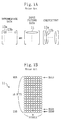
- FIGs 1A and 1B illustrate how the known two-dimensional DCT processor performs the first-stage (horizontal) one-dimensional DCT.
- each pixel data word is supposed to be represented by 16 bits.
- each set of eight horizontal pixels of input picture data (which together form one row) have bits of the same order that are identified by a bit slice BS00 , BS01 or BS15 .
- the bit slice BS00 i.e., a collection of the least significant bits (LSBs) of the eight pixels constituting a first-row vector 11 of the input picture data
- LSBs least significant bits
- bit slice BS01 and the first-column vector 12a of the transform coefficient matrix are multiplied together to obtain another partial product.
- This operation will be performed 16 times, i.e., the number of bits of each pixel data word, and all of these resulting partial products are accumulated to yield a first matrix element 13a of intermediate data.
- a multiply-add operation is performed on the first-row vector 11 of the input picture data and the second-column vector 12b of the transform coefficient matrix to yield a second matrix element 13b of the intermediate data.
- the known two-dimensional DCT processor yields the respective matrix elements of the intermediate data horizontally.
- the second-stage (vertical) one-dimensional DCT cannot be started at least until the 57 th matrix element (i.e., the first element on the eighth row) of the intermediate data is determined.
- the latency which is represented as the number of cycles required after the first pixel data was input and before the first transformed data is output, becomes relatively long.
- a memory for storing the result of the first-stage (horizontal) one-dimensional DCT thereon is indispensable for the known two-dimensional DCT processor.
- IDCT two-dimensional inverse DCT
- the order of processing is changed for the first-stage one-dimensional orthogonal transformation so that a data sequence needed for the second-stage one-dimensional orthogonal transformation can be yielded faster.
- a matrix representing desired resultant data is computed by performing the steps of: obtaining an intermediate matrix by applying a horizontal one-dimensional orthogonal transformation to respective row vectors of a matrix representing input data; and applying a vertical one-dimensional orthogonal transformation to respective column vectors of the intermediate matrix.
- the inventive method is characterized in that the horizontal one-dimensional orthogonal transformation is carried out in such an order that once all elements of one of the column vectors of the intermediate matrix have been obtained, a first element of a next one of the column vectors is obtained.
- the vertical one-dimensional orthogonal transformation can be started.
- the latency caused by the two-dimensional orthogonal transformation can be shortened and no memory is needed to store the result of the first-stage one-dimensional orthogonal transformation thereon.
- Figures 2A and 2B illustrate how to perform the first-stage (horizontal) one-dimensional orthogonal transformation according to the inventive two-dimensional orthogonal transformation method. It should be noted that this method is applicable not only to two-dimensional DCT but also to two-dimensional IDCT.
- each set of eight horizontal pixels of the first-row vector 21a of the input picture data have bits of the same order that are identified by a bit slice BS00 , BS01 or BS15 .
- bit slice BS00 i.e., a collection of the LSBs of the eight pixels constituting the first-row vector 21a of the input picture data
- bit slice BS01 and the first-column vector 22 of the transform coefficient matrix are multiplied together to obtain another partial product.
- This operation will be performed on 16 bits and all of these resulting partial products are accumulated to yield a first matrix element 23a of intermediate data.
- the next operation will be performed in the same way.
- the computation is carried out in a vertical order as opposed to the prior art.
- the multiply-add operation is performed on the second-row vector 21b of the input picture data and the first-column vector 22 of the transform coefficient matrix to yield a second matrix element 23b of the intermediate data. Since the respective matrix elements of the intermediate data are yielded vertically, the second-stage (vertical) one-dimensional DCT can be started as soon as the 8 th matrix element (on the first column) of the intermediate data is obtained.
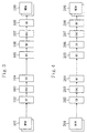
- FIG. 3 illustrates an exemplary arrangement for a two-dimensional DCT processor utilizing the inventive method.
- the processor includes memories (MEMs) 101 and 109 , butterfly operation units (BFs) 102 and 106 , ROM-and-accumulators (RACs) 103 and 107 , shufflers (SHs) 104 and 108 and a bit slicer (BS) 105 .
- MEM 101 can read and write any bit at any address and has already stored macroblock data thereon.
- the macroblock data is read out from MEM 101 one block after another, e.g., on a bit slice basis as shown in Figures 2A and 2B , and passed to BF 102 .
- BF 102 performs a butterfly operation on the bit slice of the data and outputs the result to RAC 103 .
- RAC 103 prepares a table for the butterflied data with respective addresses and accumulates the data using the table. Then, the accumulated data is sent to, and shuffled by, SH 104 . In this manner, the first-stage (horizontal) one-dimensional DCT is completed.
- BS 105 slices the data into respective bit slices, each composed of 8 pixels.
- BF 106 performs a butterfly operation on the bit slices of the data and outputs the result to RAC 107 .
- RAC 107 prepares a table for the butterflied data with respective addresses and accumulates the data using the table. Then, the accumulated data is sent to, and shuffled by, SH 108 . In this manner, the second-stage (vertical) one-dimensional DCT is completed.
- the result of the two-dimensional DCT performed in this manner is stored on MEM 109 .
- FIG. 4 illustrates an exemplary arrangement for a two-dimensional IDCT processor utilizing the inventive method.
- the processor includes memories (MEMs) 201 and 209 , shufflers (SHs) 202 and 206 , ROM-and-accumulators (RACs) 203 and 207 , butterfly operation units (BFs) 204 and 208 and a bit slicer (BS) 205 .
- MEM 201 can read and write any bit at any address and has already stored macroblock data thereon.
- the macroblock data is read out from MEN 201 one block after another, e.g., on a bit slice basis as shown in Figures 2A and 2B , and passed to SH 202 .
- SH 202 shuffles the bit slice of the data and outputs the result to RAC 203 .
- RAC 203 prepares a table for the shuffled data with respective addresses and accumulates the data using the table. Then, the accumulated data is sent to, and butterflied by, BF 204 . In this manner, the first-stage (horizontal) one-dimensional IDCT is completed.
- BS 205 slices the data into respective bit slices, each composed of 8 pixels.
- SH 206 shuffles the bit slices of the data and outputs the result to RAC 207 .
- RAC 207 prepares a table for the shuffled data with respective addresses and accumulates the data using the table. Then, the accumulated data is sent to, and butterflied by, BF 208 . In this manner, the second-stage (vertical) one-dimensional IDCT is completed.
- the result of the two-dimensional IDCT performed in this manner is stored on MEM 209 .
- FIG. 5 illustrates an exemplary arrangement for a two-dimensional DCT/IDCT processor utilizing the inventive method.
- the processor includes memories (MEMs) 301 and 309 , butterfly operation units/shufflers (BFs/SHs) 302 and 306 , ROM-and-accumulators (RACs) 303 and 307 , shufflers/butterfly operation units (SHs/BFs) 304 and 308 and a bit slicer (BS) 305 .
- MEM 301 can read and write any bit at any address and has already stored macroblock data thereon.
- the macroblock data is read out from MEM 301 one block after another, e.g., on a bit slice basis as shown in Figures 2A and 2B , and passed to BF/SH 302 .
- BF/SH 302 performs butterfly operation and shuffling on the bit slice of the data and outputs the result to RAC 303 .
- RAC 303 prepares a table for the butterflied and shuffled data with respective addresses and accumulates the data using the table. Then, the accumulated data is sent to, and shuffled and butterflied by, SH/BF 304 . In this manner, the first-stage (horizontal) one-dimensional DCT/IDCT is completed.
- BS 305 slices the data into respective bit slices, each composed of 8 pixels.
- BF/SH 306 performs butterfly operation and shuffling on the bit slices of the data and outputs the result to RAC 307 .
- RAC 307 prepares a table for the butterflied and shuffled data with respective addresses and accumulates the data using the table. Then, the accumulated data is sent to, and shuffled and butterflied by, SH/BF 308 . In this manner, the second-stage (vertical) one-dimensional DCT/IDCT is completed.
- the result of the two-dimensional DCT/IDCT performed in this manner is stored on MEM 309 .
- FIG. 6 illustrates an exemplary arrangement for another two-dimensional DCT/IDCT processor utilizing the inventive method.
- the processor includes memories (MEMs) 401 and 408 , a butterfly operation unit/shuffler (BF/SH) 402 , ROM-and-accumulators (RACs) 403 and 406 , a butterfly operation unit and shuffler (BF+SH) 404 , a bit slicer (BS) 405 and a shuffler/butterfly operation unit (SH/BF) 407 .
- MEMs memories
- BF/SH butterfly operation unit/shuffler
- RACs ROM-and-accumulators
- BF+SH butterfly operation unit and shuffler
- BS bit slicer
- SH/BF shuffler/butterfly operation unit
- MEM 401 , BF/SH 402 , RAC 403 and BS 405 are the same as the counterparts 301 , 302 , 303 and 305 , respectively, shown in Figure 5 .
- RAC 406 , SH/BF 407 and MEM 408 are the same as the counterparts 307 , 308 and 309 , respectively, shown in Figure 5 .
- SH/BF 304 and BF/SH 306 have totally the same configuration.
- the data may be processed by BF/SH 306 and then by BS 305 , which is opposite to the order illustrated in Figure 5 .
- SH/BF 304 and BF/SH 306 are combined into BF+SH 404 to reduce the circuit size.
- the processor shown in Figure 6 is the same as that shown in Figure 5 .
Landscapes
- Engineering & Computer Science (AREA)
- Physics & Mathematics (AREA)
- General Physics & Mathematics (AREA)
- Mathematical Physics (AREA)
- Theoretical Computer Science (AREA)
- Computational Mathematics (AREA)
- Mathematical Analysis (AREA)
- Mathematical Optimization (AREA)
- Pure & Applied Mathematics (AREA)
- Data Mining & Analysis (AREA)
- Algebra (AREA)
- Software Systems (AREA)
- General Engineering & Computer Science (AREA)
- Databases & Information Systems (AREA)
- Compression Or Coding Systems Of Tv Signals (AREA)
- Compression, Expansion, Code Conversion, And Decoders (AREA)
- Compression Of Band Width Or Redundancy In Fax (AREA)
- Complex Calculations (AREA)
Abstract
First, a multiply-add operation is performed on a first-row
vector of input picture data and a first-column vector of
a transform coefficient matrix to yield a first matrix
element of intermediate data. Next, a multiply-add operation
is performed on a second-row vector of the input picture data
and the first-column vector of the transform coefficient
matrix to obtain a second matrix element of the intermediate
data. In this manner, respective matrix elements are yielded
vertically for the intermediate data in performing the first-stage
(horizontal) one-dimensional orthogonal transformation.
Thus, as soon as the 8th matrix element (of the first column)
has been obtained for the intermediate data, the second-stage
(vertical) one-dimensional orthogonal transformation can be
started. Consequently, desired resultant data of the two-dimensional
orthogonal transformation can be obtained much
faster and no memories are needed to store the result of the
first-stage one-dimensional orthogonal transformation thereon.
Description
- The present invention relates to a two-dimensional orthogonal transformation method applicable to a recorder-player (e.g., videotape recorder or videodisk player) for digitally writing and reading a video or audio signal.
- A recorder-player for a moving picture signal compresses, transmits and stores data not just by motion compensation/estimation, orthogonal transformation (e.g., discrete cosine transform (DCT), in particular) and band division but also by variable length coding (VLC) like Huffman coding and arithmetic coding. For example, according to an MPEG standard, which is one of the international video compression standards, data is supposed to be processed on a macroblock basis to increase a compression rate. A macroblock is a coding unit composed of 16 vertical pixels by 16 horizontal pixels, and can be sub-divided into four blocks, each consisting of 8×8 pixels.
- A two-dimensional DCT processor using distributed arithmetic (DA) is disclosed in United States Patent No. 4,791,598. The processor applies first-stage (horizontal) one-dimensional DCT to respective row vectors of a matrix that represents one block of input data (i.e., pixel data), thereby obtaining all the elements of an intermediate transform matrix. Next, the processor transposes the intermediate transform matrix and then performs second-stage (vertical) one-dimensional DCT on respective row vectors in the transpose of the intermediate transform matrix to yield a two-dimensional transformed matrix representing desired resultant data (transformed data).
- Figures 1A and 1B illustrate how the known two-dimensional DCT processor performs the first-stage (horizontal) one-dimensional DCT. In the illustrated example, each pixel data word is supposed to be represented by 16 bits. In Figure 1B, each set of eight horizontal pixels of input picture data (which together form one row) have bits of the same order that are identified by a bit slice BS00, BS01 or BS15. AS shown in Figure 1A, first, the bit slice BS00 (i.e., a collection of the least significant bits (LSBs) of the eight pixels constituting a first-
row vector 11 of the input picture data) is multiplied by a first-column vector 12a of a transform coefficient matrix to obtain a partial product. Next, the bit slice BS01 and the first-column vector 12a of the transform coefficient matrix are multiplied together to obtain another partial product. This operation will be performed 16 times, i.e., the number of bits of each pixel data word, and all of these resulting partial products are accumulated to yield afirst matrix element 13a of intermediate data. In the same way, a multiply-add operation is performed on the first-row vector 11 of the input picture data and the second-column vector 12b of the transform coefficient matrix to yield asecond matrix element 13b of the intermediate data. - The known two-dimensional DCT processor yields the respective matrix elements of the intermediate data horizontally. Thus, the second-stage (vertical) one-dimensional DCT cannot be started at least until the 57th matrix element (i.e., the first element on the eighth row) of the intermediate data is determined. As a result, the latency, which is represented as the number of cycles required after the first pixel data was input and before the first transformed data is output, becomes relatively long. In addition, a memory for storing the result of the first-stage (horizontal) one-dimensional DCT thereon is indispensable for the known two-dimensional DCT processor. The same statements are also true of a known two-dimensional inverse DCT (IDCT) processor.
- It is therefore an object of the present invention to obtain desired resultant data of a two-dimensional orthogonal transformation much faster without using any memory for storing the result of the first-stage one-dimensional orthogonal transformation thereon.
- To achieve this object, according to the present invention, the order of processing is changed for the first-stage one-dimensional orthogonal transformation so that a data sequence needed for the second-stage one-dimensional orthogonal transformation can be yielded faster.
- Specifically, in an inventive two-dimensional orthogonal transformation method, a matrix representing desired resultant data is computed by performing the steps of: obtaining an intermediate matrix by applying a horizontal one-dimensional orthogonal transformation to respective row vectors of a matrix representing input data; and applying a vertical one-dimensional orthogonal transformation to respective column vectors of the intermediate matrix. The inventive method is characterized in that the horizontal one-dimensional orthogonal transformation is carried out in such an order that once all elements of one of the column vectors of the intermediate matrix have been obtained, a first element of a next one of the column vectors is obtained.
- In one embodiment of the present invention, as soon as a last element of a first one of the column vectors of the intermediate matrix has been obtained, the vertical one-dimensional orthogonal transformation can be started. As a result, the latency caused by the two-dimensional orthogonal transformation can be shortened and no memory is needed to store the result of the first-stage one-dimensional orthogonal transformation thereon.
-
- Figures 1A and 1B schematically illustrate how to perform first-stage one-dimensional orthogonal transformation by a known two-dimensional orthogonal transformation method.
- Figures 2A and 2B schematically illustrate how to perform first-stage one-dimensional orthogonal transformation by an inventive two-dimensional orthogonal transformation method.
- Figure 3 is a block diagram illustrating an exemplary arrangement for a two-dimensional DCT processor utilizing the inventive method.
- Figure 4 is a block diagram illustrating an exemplary arrangement for a two-dimensional IDCT processor utilizing the inventive method.
- Figure 5 is a block diagram illustrating an exemplary arrangement for a two-dimensional DCT/IDCT processor utilizing the inventive method.
- Figure 6 is a block diagram illustrating an exemplary arrangement for another two-dimensional DCT/IDCT processor utilizing the inventive method.
-
- Figures 2A and 2B illustrate how to perform the first-stage (horizontal) one-dimensional orthogonal transformation according to the inventive two-dimensional orthogonal transformation method. It should be noted that this method is applicable not only to two-dimensional DCT but also to two-dimensional IDCT.
- In Figure 2B, each set of eight horizontal pixels of the first-
row vector 21a of the input picture data have bits of the same order that are identified by a bit slice BS00, BS01 or BS15. As shown in Figure 2A, first, the bit slice BS00 (i.e., a collection of the LSBs of the eight pixels constituting the first-row vector 21a of the input picture data) is multiplied by a first-column vector 22 of a transform coefficient matrix to obtain a partial product. Next, the bit slice BS01 and the first-column vector 22 of the transform coefficient matrix are multiplied together to obtain another partial product. This operation will be performed on 16 bits and all of these resulting partial products are accumulated to yield afirst matrix element 23a of intermediate data. The next operation will be performed in the same way. However, according to the present invention, the computation is carried out in a vertical order as opposed to the prior art. Specifically, the multiply-add operation is performed on the second-row vector 21b of the input picture data and the first-column vector 22 of the transform coefficient matrix to yield asecond matrix element 23b of the intermediate data. Since the respective matrix elements of the intermediate data are yielded vertically, the second-stage (vertical) one-dimensional DCT can be started as soon as the 8th matrix element (on the first column) of the intermediate data is obtained. - Figure 3 illustrates an exemplary arrangement for a two-dimensional DCT processor utilizing the inventive method. As shown in Figure 3, the processor includes memories (MEMs) 101 and 109, butterfly operation units (BFs) 102 and 106, ROM-and-accumulators (RACs) 103 and 107, shufflers (SHs) 104 and 108 and a bit slicer (BS) 105. MEM 101 can read and write any bit at any address and has already stored macroblock data thereon.
- The macroblock data is read out from
MEM 101 one block after another, e.g., on a bit slice basis as shown in Figures 2A and 2B, and passed toBF 102. BF 102 performs a butterfly operation on the bit slice of the data and outputs the result toRAC 103. RAC 103 prepares a table for the butterflied data with respective addresses and accumulates the data using the table. Then, the accumulated data is sent to, and shuffled by,SH 104. In this manner, the first-stage (horizontal) one-dimensional DCT is completed. - Next, to perform the second-stage (vertical) one-dimensional DCT,
BS 105 slices the data into respective bit slices, each composed of 8 pixels. BF 106 performs a butterfly operation on the bit slices of the data and outputs the result toRAC 107.RAC 107 prepares a table for the butterflied data with respective addresses and accumulates the data using the table. Then, the accumulated data is sent to, and shuffled by,SH 108. In this manner, the second-stage (vertical) one-dimensional DCT is completed. Eventually, the result of the two-dimensional DCT performed in this manner is stored onMEM 109. - Figure 4 illustrates an exemplary arrangement for a two-dimensional IDCT processor utilizing the inventive method. As shown in Figure 4, the processor includes memories (MEMs) 201 and 209, shufflers (SHs) 202 and 206, ROM-and-accumulators (RACs) 203 and 207, butterfly operation units (BFs) 204 and 208 and a bit slicer (BS) 205.
MEM 201 can read and write any bit at any address and has already stored macroblock data thereon. - The macroblock data is read out from MEN 201 one block after another, e.g., on a bit slice basis as shown in Figures 2A and 2B, and passed to
SH 202.SH 202 shuffles the bit slice of the data and outputs the result toRAC 203.RAC 203 prepares a table for the shuffled data with respective addresses and accumulates the data using the table. Then, the accumulated data is sent to, and butterflied by,BF 204. In this manner, the first-stage (horizontal) one-dimensional IDCT is completed. - Next, to perform the second-stage (vertical) one-dimensional IDCT,
BS 205 slices the data into respective bit slices, each composed of 8 pixels.SH 206 shuffles the bit slices of the data and outputs the result toRAC 207.RAC 207 prepares a table for the shuffled data with respective addresses and accumulates the data using the table. Then, the accumulated data is sent to, and butterflied by,BF 208. In this manner, the second-stage (vertical) one-dimensional IDCT is completed. Eventually, the result of the two-dimensional IDCT performed in this manner is stored onMEM 209. - Figure 5 illustrates an exemplary arrangement for a two-dimensional DCT/IDCT processor utilizing the inventive method. As shown in Figure 5, the processor includes memories (MEMs) 301 and 309, butterfly operation units/shufflers (BFs/SHs) 302 and 306, ROM-and-accumulators (RACs) 303 and 307, shufflers/butterfly operation units (SHs/BFs) 304 and 308 and a bit slicer (BS) 305.
MEM 301 can read and write any bit at any address and has already stored macroblock data thereon. - The macroblock data is read out from
MEM 301 one block after another, e.g., on a bit slice basis as shown in Figures 2A and 2B, and passed to BF/SH 302. BF/SH 302 performs butterfly operation and shuffling on the bit slice of the data and outputs the result toRAC 303.RAC 303 prepares a table for the butterflied and shuffled data with respective addresses and accumulates the data using the table. Then, the accumulated data is sent to, and shuffled and butterflied by, SH/BF 304. In this manner, the first-stage (horizontal) one-dimensional DCT/IDCT is completed. - Next, to perform the second-stage (vertical) one-dimensional DCT/IDCT, BS 305 slices the data into respective bit slices, each composed of 8 pixels. BF/SH 306 performs butterfly operation and shuffling on the bit slices of the data and outputs the result to RAC 307. RAC 307 prepares a table for the butterflied and shuffled data with respective addresses and accumulates the data using the table. Then, the accumulated data is sent to, and shuffled and butterflied by, SH/BF 308. In this manner, the second-stage (vertical) one-dimensional DCT/IDCT is completed. Eventually, the result of the two-dimensional DCT/IDCT performed in this manner is stored on MEM 309.
- Figure 6 illustrates an exemplary arrangement for another two-dimensional DCT/IDCT processor utilizing the inventive method. As shown in Figure 6, the processor includes memories (MEMs) 401 and 408, a butterfly operation unit/shuffler (BF/SH) 402, ROM-and-accumulators (RACs) 403 and 406, a butterfly operation unit and shuffler (BF+SH) 404, a bit slicer (BS) 405 and a shuffler/butterfly operation unit (SH/BF) 407.
- In this case,
MEM 401, BF/SH 402,RAC 403 andBS 405 are the same as thecounterparts BF 304 and BF/SH 306 have totally the same configuration. And the data may be processed by BF/SH 306 and then by BS 305, which is opposite to the order illustrated in Figure 5. Thus, in the example illustrated in Figure 6, SH/BF 304 and BF/SH 306 are combined into BF+SH 404 to reduce the circuit size. In the other respects, the processor shown in Figure 6 is the same as that shown in Figure 5.
Claims (2)
- A two-dimensional orthogonal transformation method for computing a matrix representing desired resultant data by performing the steps of:obtaining an intermediate matrix by applying a horizontal one-dimensional orthogonal transformation to respective row vectors of a matrix representing input data; andapplying a vertical one-dimensional orthogonal transformation to respective column vectors of the intermediate matrix,
characterized in that the horizontal one-dimensional orthogonal transformation is carried out in such an order that once all elements of one of the column vectors of the intermediate matrix have been obtained, a first element of a next one of the column vectors is obtained. - The method of Claim 1, wherein as soon as a last element of a first one of the column vectors of the intermediate matrix has been obtained, the vertical one-dimensional orthogonal transformation is started.
Applications Claiming Priority (2)
| Application Number | Priority Date | Filing Date | Title |
|---|---|---|---|
| JP31073499A JP2001128177A (en) | 1999-11-01 | 1999-11-01 | Two-dimensional orthogonal transformation method |
| JP31073499 | 1999-11-01 |
Publications (1)
| Publication Number | Publication Date |
|---|---|
| EP1096390A2 true EP1096390A2 (en) | 2001-05-02 |
Family
ID=18008852
Family Applications (1)
| Application Number | Title | Priority Date | Filing Date |
|---|---|---|---|
| EP20000123881 Withdrawn EP1096390A2 (en) | 1999-11-01 | 2000-11-02 | Two-dimensional orthogonal transformation method |
Country Status (2)
| Country | Link |
|---|---|
| EP (1) | EP1096390A2 (en) |
| JP (1) | JP2001128177A (en) |
Cited By (2)
| Publication number | Priority date | Publication date | Assignee | Title |
|---|---|---|---|---|
| CN104113758A (en) * | 2014-07-10 | 2014-10-22 | 四川大学 | Measurement matrix optimization method based on matrix elementary transformation |
| CN111611595A (en) * | 2020-04-01 | 2020-09-01 | 北京奇艺世纪科技有限公司 | Data encryption method and device |
Families Citing this family (1)
| Publication number | Priority date | Publication date | Assignee | Title |
|---|---|---|---|---|
| US9554152B2 (en) * | 2013-07-12 | 2017-01-24 | Qualcomm Incorporated | Concurrent processing of horizontal and vertical transforms |
-
1999
- 1999-11-01 JP JP31073499A patent/JP2001128177A/en active Pending
-
2000
- 2000-11-02 EP EP20000123881 patent/EP1096390A2/en not_active Withdrawn
Cited By (3)
| Publication number | Priority date | Publication date | Assignee | Title |
|---|---|---|---|---|
| CN104113758A (en) * | 2014-07-10 | 2014-10-22 | 四川大学 | Measurement matrix optimization method based on matrix elementary transformation |
| CN111611595A (en) * | 2020-04-01 | 2020-09-01 | 北京奇艺世纪科技有限公司 | Data encryption method and device |
| CN111611595B (en) * | 2020-04-01 | 2023-06-30 | 北京奇艺世纪科技有限公司 | Data encryption method and device |
Also Published As
| Publication number | Publication date |
|---|---|
| JP2001128177A (en) | 2001-05-11 |
Similar Documents
| Publication | Publication Date | Title |
|---|---|---|
| US7079698B2 (en) | Image coding and decoding apparatus, method of image coding and decoding, and recording medium for recording program for image coding and decoding | |
| KR940023246A (en) | Predictive encoded video signal reproduction apparatus and method | |
| US5905846A (en) | Image decoding apparatus and process thereof and image reproduction apparatus | |
| JP4688988B2 (en) | Video data compression method and apparatus, and decompression method and apparatus | |
| DE112006002148T5 (en) | Exchange buffer for video processing | |
| EP1096390A2 (en) | Two-dimensional orthogonal transformation method | |
| EP0566184A2 (en) | Picture transformer and television system with a transmitter and a receiver comprising a picture transformer | |
| US6111989A (en) | 1/4 size real time decoding of digital video | |
| US6092920A (en) | Method for arranging pixels to facilitate compression/extension of image data | |
| KR100377084B1 (en) | Discrete cosine conversion circuit, discrete cosine inverse conversion circuit, MPEG video encoder and MPEG video decoder | |
| US20030133507A1 (en) | Adaptive inverse transformation device | |
| US6507673B1 (en) | Method and apparatus for video encoding decision | |
| JPWO1993021731A1 (en) | Image Reproduction Device | |
| JPH0844708A (en) | Two-dimensional discrete cosine transform arithmetic circuit | |
| TW468341B (en) | Video encoder having an integrated scaling mechanism | |
| JP3061125B2 (en) | MPEG image reproducing apparatus and MPEG image reproducing method | |
| JP2000069478A (en) | Image processing apparatus and method, and storage medium | |
| JP4511451B2 (en) | Decoding method and decoding apparatus | |
| JPH07184212A (en) | Memory system | |
| JP4590335B2 (en) | Image processing apparatus and image processing method | |
| US20090110316A1 (en) | Apparatus and method for performing video decoding processes in parallel | |
| US20070065035A1 (en) | Image processing method and two-dimension discrete cosine transformation device using the same | |
| US5905660A (en) | Discrete cosine transform circuit for processing an 8×8 block and two 4×8 blocks | |
| JP2005218055A (en) | Image processing apparatus, image processing method, and image processing program | |
| JP2006503488A (en) | Image resizing method using inverse discrete cosine transform |
Legal Events
| Date | Code | Title | Description |
|---|---|---|---|
| PUAI | Public reference made under article 153(3) epc to a published international application that has entered the european phase |
Free format text: ORIGINAL CODE: 0009012 |
|
| AK | Designated contracting states |
Kind code of ref document: A2 Designated state(s): AT BE CH CY DE DK ES FI FR GB GR IE IT LI LU MC NL PT SE TR |
|
| AX | Request for extension of the european patent |
Free format text: AL;LT;LV;MK;RO;SI |
|
| STAA | Information on the status of an ep patent application or granted ep patent |
Free format text: STATUS: THE APPLICATION HAS BEEN WITHDRAWN |
|
| 18W | Application withdrawn |
Effective date: 20070105 |