EP1096309A1 - A photographic printing apparatus with a web transport assembly for plural media supplies/take-ups - Google Patents
A photographic printing apparatus with a web transport assembly for plural media supplies/take-ups Download PDFInfo
- Publication number
- EP1096309A1 EP1096309A1 EP00203429A EP00203429A EP1096309A1 EP 1096309 A1 EP1096309 A1 EP 1096309A1 EP 00203429 A EP00203429 A EP 00203429A EP 00203429 A EP00203429 A EP 00203429A EP 1096309 A1 EP1096309 A1 EP 1096309A1
- Authority
- EP
- European Patent Office
- Prior art keywords
- media
- roller
- transport assembly
- section
- supply
- Prior art date
- Legal status (The legal status is an assumption and is not a legal conclusion. Google has not performed a legal analysis and makes no representation as to the accuracy of the status listed.)
- Granted
Links
- 230000007246 mechanism Effects 0.000 description 3
- 230000003993 interaction Effects 0.000 description 2
- 238000000034 method Methods 0.000 description 2
- 238000004080 punching Methods 0.000 description 2
- 230000000712 assembly Effects 0.000 description 1
- 238000000429 assembly Methods 0.000 description 1
- 238000010586 diagram Methods 0.000 description 1
- 230000000694 effects Effects 0.000 description 1
- 230000013011 mating Effects 0.000 description 1
- 230000007723 transport mechanism Effects 0.000 description 1
- 238000011144 upstream manufacturing Methods 0.000 description 1
Images




Classifications
-
- G—PHYSICS
- G03—PHOTOGRAPHY; CINEMATOGRAPHY; ANALOGOUS TECHNIQUES USING WAVES OTHER THAN OPTICAL WAVES; ELECTROGRAPHY; HOLOGRAPHY
- G03B—APPARATUS OR ARRANGEMENTS FOR TAKING PHOTOGRAPHS OR FOR PROJECTING OR VIEWING THEM; APPARATUS OR ARRANGEMENTS EMPLOYING ANALOGOUS TECHNIQUES USING WAVES OTHER THAN OPTICAL WAVES; ACCESSORIES THEREFOR
- G03B27/00—Photographic printing apparatus
- G03B27/32—Projection printing apparatus, e.g. enlarger, copying camera
- G03B27/46—Projection printing apparatus, e.g. enlarger, copying camera for automatic sequential copying of different originals, e.g. enlargers, roll film printers
- G03B27/462—Projection printing apparatus, e.g. enlarger, copying camera for automatic sequential copying of different originals, e.g. enlargers, roll film printers in enlargers, e.g. roll film printers
-
- G—PHYSICS
- G03—PHOTOGRAPHY; CINEMATOGRAPHY; ANALOGOUS TECHNIQUES USING WAVES OTHER THAN OPTICAL WAVES; ELECTROGRAPHY; HOLOGRAPHY
- G03B—APPARATUS OR ARRANGEMENTS FOR TAKING PHOTOGRAPHS OR FOR PROJECTING OR VIEWING THEM; APPARATUS OR ARRANGEMENTS EMPLOYING ANALOGOUS TECHNIQUES USING WAVES OTHER THAN OPTICAL WAVES; ACCESSORIES THEREFOR
- G03B27/00—Photographic printing apparatus
- G03B27/32—Projection printing apparatus, e.g. enlarger, copying camera
-
- G—PHYSICS
- G03—PHOTOGRAPHY; CINEMATOGRAPHY; ANALOGOUS TECHNIQUES USING WAVES OTHER THAN OPTICAL WAVES; ELECTROGRAPHY; HOLOGRAPHY
- G03B—APPARATUS OR ARRANGEMENTS FOR TAKING PHOTOGRAPHS OR FOR PROJECTING OR VIEWING THEM; APPARATUS OR ARRANGEMENTS EMPLOYING ANALOGOUS TECHNIQUES USING WAVES OTHER THAN OPTICAL WAVES; ACCESSORIES THEREFOR
- G03B27/00—Photographic printing apparatus
- G03B27/32—Projection printing apparatus, e.g. enlarger, copying camera
- G03B27/52—Details
- G03B27/58—Baseboards, masking frames, or other holders for the sensitive material
- G03B27/587—Handling photosensitive webs
- G03B27/588—Supply rolls; Cutting arrangements
Definitions
- the present invention relates to a printing apparatus which can feed a long strip of media, such as photographic paper more or less continuously from a supply cassette, to a supply section, to a printing section, and thereafter to a take-up section.
- the printing apparatus of the present invention is of a modular design and is configured to provide for vertical twisted web paths while at the same time minimizing web tracking variation.
- a complex shuttle mechanism and complex paper handling are required.
- a web of photosensitive media such as photosensitive paper
- a splicer for the purpose of splicing the photosensitive media at the supply side of a multi-cassette arrangement, it is necessary to divert the paper into a splicer separately for each entry position of the cassette.
- the present invention provides for a printing apparatus having multiple supply cassettes and take-up cassettes which is of a modular design and creates a paper path that follows an exact constraint design.
- the paper path of the printing apparatus of the present invention is configured to accept media from a plurality of supply cassettes and deliver media to a plurality of take-up cassettes.
- the paper path is separated into tensioned web spans which include, for example, a paper supply span, a paper punching span, a write engine span and a paper take-up span.
- the spans can be isolated from each other by motion control slack loops.
- the printing apparatus of the present invention comprises three separable sections, which include a supply section, a center printing section, and a take-up section.
- the breaks between the above sections are preferably located within the supply and the take-up sections, and are the locations in which the web can undergo a vertical twist.
- This vertical twist is the result of a pivoting of the paper path by an angle of between 0-90 degrees, for example, an angle of ⁇ 30 degrees between the plurality of supply cassettes and take-up cassettes.
- the design of the present invention provides for exact constraint web handling while at the same time, minimizing the effect that twisting and frame tolerances have on web tracking.
- the present invention provides for a printing apparatus which comprises a media supply section having a transport assembly and a plurality of media entry openings.
- the transport assembly is rotatable to each of the media entry openings so as to accept media from a selected one of the media entry openings.
- the printing apparatus further comprises a printing section which is adapted to accept the media from the media supply section and a take-up section which is adapted to receive media from the printing section.
- the take-up section includes a take-up assembly and a plurality of media exit openings.
- the take-up assembly is rotatable to each of the media exit openings so as to discharge media through a selected one of the media exit openings.
- the present invention also provides for a printing apparatus which includes a media supply section comprising a first transport assembly that conveys media along a first transport assembly longitudinal axis.
- the first transport assembly is rotatable between a plurality of supply entry ports on the media supply section to selectively accept media from each of the supply entry ports.
- the first transport assembly further comprises at least one first roller which is rotatable with respect to the first transport assembly about the first transport assembly longitudinal axis.
- the printing apparatus further comprises a printing section that receives media from the media supply section.
- the printing section comprises a first guide plate that guides media from the at least one first roller into the printing section.
- the first transport assembly has at least one rotatable position which creates a twist in a media span of the media between the at least one first roller and the first guide plate.
- the present invention further provides for a media supply assembly which comprises a plurality of media entry ports; a transport assembly that is rotatable to each of the media entry ports to receive and convey media entering through the media entry ports along a longitudinal axis; and at least one roller mounted on the transport assembly so as to be rotatable about the longitudinal axis.
- the at least one roller conveys media along the transport assembly toward an exit port of the media supply assembly.
- the present invention further provides for a media take-out assembly that comprises a media entry port; a plurality of media exit ports; a transport assembly that conveys media from the media entry port to one of the media exit ports, with the transport assembly being rotatable to each of the media exit ports; and at least one first roller mounted on the transport assembly so as to rotate about a pivot point which is spaced from a rotational axis of the at least one first roller.
- the present invention further provides for a printing apparatus that comprises a rotatable transport assembly provided at least at one of an input side or output side of a printing section.
- the transport assembly is adapted to twist a web of photosensitive media about a vertical axis as the photosensitive media is conveyed through the printing apparatus.
- Fig. 1 is an overall view of a printing apparatus 15 in accordance with the present invention.
- printing apparatus 15 comprises a media supply section 17 and a media take-up section 19.
- Media supply section 17 is adapted to accommodate a plurality of media supply cassettes 17a-17c
- media take-up section 19 is adapted to accommodate a plurality of media take-up cassettes 19a-19c.
- supply cassettes 17a-17c and take-up cassettes 19a-19c are wheel cassettes, which facilitate the interaction between the cassettes and the corresponding supply section and take-out sections (17, 19), however, the invention is not limited thereto, and the cassettes do not have to be wheeled cassettes.
- supply cassettes 17a-17c can each contain a roll 23 of, for example, photosensitive media that is to be processed through a printing section 21.
- Take-up cassettes 19a-19c on the take-up side are initially empty and each include a shaft 90 adapted to receive a roll of photosensitive media after the web has past through printing section 21.
- supply cassettes 17a-17c and take-up cassettes 19a-19c are provided at three locations and are angularly positioned with respect to each other.
- the invention is not limited thereto, and the cassettes can be located at various angles, while the printing apparatus can include more than three or less than three cassettes at each of the supply and take-up sides.
- supply cassette 17a which is seen in the view of Fig. 3 includes supply roll 23 of media such as, for example, photosensitive media.
- Supply section 17 includes a plurality of entry openings or ports 25 which mate with a corresponding port or opening in supply cassettes 17a-17c to permit a web 100 of photosensitive material to enter into supply section 17. Only one entry port 25 is illustrated in Fig. 3. It is recognized that supply section 17 includes entry ports 25 corresponding in number and location with a respective supply cassette 17a-17c.
- transport assembly 27 which is rotatable to a plurality of positions to mate with each of the media entry ports 25 which correspond to each of the supply cassettes 17a, 17b and 17c.
- a pair of drive rollers. 30 convey the web of photosensitive material into transport assembly 27, where a further arrangement of drive rollers 33 transport the web of photosensitive material through transport assembly 27.
- transport assembly 27 is rotatable between each of the entry ports 25 so as to selectively accept media from each of the supply cassettes 17a, 17b, 17c.
- transport mechanism 27 is simply pivoted or rotated about point 29 to the next appropriate position having a cassette (17a, 17b, 17c) with a supply of photosensitive material.
- a feature of the present invention with respect to the rotatable transport assembly 27 is the creation of a vertical twist at an angle of between 0-90 degrees and preferably approximately ⁇ 30 degrees about a vertical axis in the photosensitive web. More specifically, as illustrated in Figs. 2-6, transport assembly 27 includes a roller 35 which is gimballed. Referring to Fig. 6 which illustrates one mounting example for gimballed roller 35, it is seen that roller 35 can be mounted on a roller support 35a so as to be rotatable with respect to transport assembly 27 about a longitudinal axis 35b of a media span approaching roller 35.
- This arrangement creates a first web span of media which extends from supply roll 23 to gimballed roller 35.
- a lateral position 110 of the span of media from supply roll 23 to gimballed roller 35 is derived by supply roll 23, while an angular position 115 of the media from supply roll 23 to the gimballed roller 35 is derived by gimballed roller 35.
- supply section 17 includes a guiding shoe or plate 37, which helps guide the photosensitive material toward gimballed roller 35.
- gimballed roller 35 when the media is being first supplied from cassette 17a, gimballed roller 35 will pivot to accommodate the twisting of the web. Gimballed roller 35 guides the web or material through an approximately 90 degree bend and then in an upward vertical direction into printing section 21 as illustrated in Figs. 2-4.
- Printing section 21 can include a guiding plate or shoe 39 (Fig. 4) which changes the conveying direction of the web, and a drive and pressure roller arrangement 41. Therefore, the span of the photosensitive material between roller 35 and drive and pressure roller arrangement 41 defines a second span of the photosensitive material passing through printing apparatus 15.
- gimballed roller 35 essentially acts as a hinge between the span of photosensitive material between supply roll 23 and gimballed roller 35, and the span of photosensitive material between gimballed roller 35 and drive and pressure roller arrangement 41.
- This is conceptually illustrated in Fig. 5 of the application.
- Gimballed roller 35 which rotates as a unit with transport assembly 27 will pivot with respect to transport assembly 27 in accordance with the twist of the web between roller 35 and plate 39 as transport assembly 27 is rotated between supply cassettes 17a-17c.
- Printing section 21 can be part of a known laser printer. However, the present invention is not limited thereto and other types of printing systems are possible within the context of the present invention.
- the material can sequentially pass through a first slack loop 43, through a paper punching/marking section 45, through a second slack loop 47, over a print drum 49 where the material can be laser scanned in accordance with image information (obtained separately by scanning a processed film, strip), through a third slack loop 51 and into take-up section 19.
- take-up section 19 includes a pivotable or rotatable transport or take-up assembly 53 which is rotatable about point 55, so as to be in mating engagement with a corresponding media exit opening or ports 57 provided on the take-up section 19.
- take-up section 19 includes the plurality of exit openings 57 which correspond in number and location with take-up cassettes 19a, 19b, 19c.
- Take-up cassettes 19a, 19b, 19c are provided at openings 57, so that the web of photosensitive material is supplied directly to the take-up cassettes.
- transport assembly 53 is rotated about point 55 to the next take-up cassette (19a, 19b, 19c).
- a combination of a shoe or plate 59 and a lateral guide 61 is provided to guide the web towards the exit of printing section 21.
- a gimballed roller 63 is provided at the exit of printing section 21.
- Roller 63 guides the web through an approximately 90 degree bend and is mounted as previously described with respect to gimballed roller 35 and illustrated in Fig. 6.
- Rotatable transport assembly 53 includes a castered roller 65 and a castered and gimballed roller 67. The specifics of castered roller 65 are illustrated in Fig. 9.
- castered roller 65 is pivotally mounted on links 65a which pivot about points 650, 651 and are mounted on support 652.
- the axes of links 65a intersect at a point 654 which defines an upstream pivot or caster axis for roller 65.
- roller 65 rotates about rotational axis 653 and due to the interaction of links 65a rotates about an axis through point 654 which is spaced from and perpendicular to rotational axis 653. This enables roller 65 to self-align to the web.
- Castered and gimballed roller 67 is illustrated in detail in Fig. 10.
- roller 67 is mounted on a support 672 so as to be rotatable about rotational axis 670.
- Roller 67 and support 672 are mounted as a unit on a further support 673 such that roller 67 and support 672 pivot as a unit about pivot point or caster axis 674 relative to further support 673.
- Pivot point 674 is spaced from and perpendicular to rotational axis 670.
- Roller 67 is further rotatable as a unit relative to transport assembly 53 about pivot point or gimbal axis 675 which extends along a longitudinal axis of a media span at roller 67.
- Figures 9 and 10 respectively illustrate examples of mounting rollers in a castered and castered and gimballed manner. It is recognized that the present invention is not limited thereto and that other methods of mounting the rollers in a castered and castered and gimballed manner are possible within the context of the present invention.
- the web After being conveyed by castered and gimballed roller 67, which self-align to the web, the web can be upwardly conveyed to a shoe and lateral guide arrangement 69, and thereafter fed by feeding roller 71 to an appropriate take-up cassette 19a-19c.
- a third span of the photosensitive material is defined between lateral guide 61 and gimballed roller 63
- a lateral position 300 is derived by lateral guide 61, while an angular position 303 is derived from gimballed roller 63.
- a further span is defined between guide arrangement 69 and take-up roll 90.
- a lateral position 305 is derived from guide arrangement 69, while an angular position 307 is derived from take-up roll 90 in take-up cassette (19a-19c). Therefore, as conceptually illustrated in Fig.
- roller 67 is castered and gimballed so as to act as a hinge and provide zero constraint, while roller 67 is castered so as to provide zero constraint.
- a splicer 75 is provided on rotatable transport assembly 27.
- splicer 75 and gimballed roller 35 are rotatable as a unit together with transport assembly 27.
- the arrangement of the present invention permits splicer 75 to be pivotable from one cassette 17a to another cassette 17b to a further cassette 17c. This provides for a straight thrust of the web from each cassette (17a-17c) such that the span from the supply cassette (17a-17c) is always straight.
- the web can be twisted about vertical axis 500 (Fig. 4) between gimballed roller 35 and plate or shoe 39 without appreciable tracking error because the web is two dimensionally stiff at twist angles of less than 90 degrees.
- Splicer 75 serves to splice the end of the material from an empty cassette to begin the paper of a next full cassette.
- reference numeral 83 schematically illustrates the twisted web span entering the printing section 21, while reference numeral 85 schematically illustrates the twisted web span exiting the printing section 21.
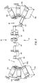
- Each of the web spans are respectively twisted about vertical axis 500 (Fig. 4) and vertical axis 501 (Fig. 7).
- a known cutter 77 is provided on transport assembly 53.
- Cutter 77 along with castered roller 65 and castered and gimballed roller 67 are rotatable as a unit with transport assembly 53.
- the cutter is utilized on the take-up side to cut the paper an appropriate length, at the termination of the roll. Thereafter, transport assembly 53 can be rotated to the next empty take-up cassette (19a- 19c).
- Control of rotatable transport assemblies 27 and 53 can be by way of a computer and/or microprocessor provided in printing apparatus 15, which control a moving mechanism such as a motor and are responsive to signals with respect to, for example, the amount of paper in the cassettes, the position of the web, etc.
- a supply cassette can include sensors which communicate with sensors within the printing section, to indicate when a supply cassette is empty or full
- a take-up cassette can include sensors to indicate the amount of paper in the take-up cassette.
- a sensor such as a counter can be provided along the web path, to count the amount of paper, and utilize this as a reference with respect to the amount of paper within a specific cassette.
- the present invention provides for a printing apparatus that permits a connection of a plurality of supply and take-up cassettes through a controlled path geometry and controlled constraints.
- the web path through the printing apparatus undergoes two approximately 90° bends at each end. At each pair of bends the web is pivoted and undergoes a twist about a vertical line or a line which is colinear to the pivot axis.
- This pivot motion permits the web to be routed to and from a plurality of supply and take-up cassettes so as to merge multiple paper paths into one central path.
- the pivot motion also creates straight feed paths to a splicer and from a cutter and eliminates the need for a complex shuttle mechanism or complicated paper handling.
Landscapes
- Physics & Mathematics (AREA)
- General Physics & Mathematics (AREA)
- Unwinding Webs (AREA)
- Replacement Of Web Rolls (AREA)
- Handling Of Continuous Sheets Of Paper (AREA)
- Rotary Presses (AREA)
- Winding Of Webs (AREA)
- Advancing Webs (AREA)
- Registering, Tensioning, Guiding Webs, And Rollers Therefor (AREA)
Abstract
Description
- The present invention relates to a printing apparatus which can feed a long strip of media, such as photographic paper more or less continuously from a supply cassette, to a supply section, to a printing section, and thereafter to a take-up section. The printing apparatus of the present invention is of a modular design and is configured to provide for vertical twisted web paths while at the same time minimizing web tracking variation.
- Conventionally, when a printing apparatus includes a plurality of supply cassettes and take-up cassettes, a complex shuttle mechanism and complex paper handling are required. For example, in an apparatus which includes a plurality of supply cassettes and take-up cassettes, it is necessary to divert a web of photosensitive media, such as photosensitive paper, through a plurality of loops which requires a complex interface. Furthermore, for the purpose of splicing the photosensitive media at the supply side of a multi-cassette arrangement, it is necessary to divert the paper into a splicer separately for each entry position of the cassette.
- The present invention provides for a printing apparatus having multiple supply cassettes and take-up cassettes which is of a modular design and creates a paper path that follows an exact constraint design. The paper path of the printing apparatus of the present invention is configured to accept media from a plurality of supply cassettes and deliver media to a plurality of take-up cassettes. The paper path is separated into tensioned web spans which include, for example, a paper supply span, a paper punching span, a write engine span and a paper take-up span. The spans can be isolated from each other by motion control slack loops.
- The printing apparatus of the present invention comprises three separable sections, which include a supply section, a center printing section, and a take-up section. The breaks between the above sections are preferably located within the supply and the take-up sections, and are the locations in which the web can undergo a vertical twist. This vertical twist is the result of a pivoting of the paper path by an angle of between 0-90 degrees, for example, an angle of ± 30 degrees between the plurality of supply cassettes and take-up cassettes. The design of the present invention provides for exact constraint web handling while at the same time, minimizing the effect that twisting and frame tolerances have on web tracking.
- The present invention provides for a printing apparatus which comprises a media supply section having a transport assembly and a plurality of media entry openings. The transport assembly is rotatable to each of the media entry openings so as to accept media from a selected one of the media entry openings. The printing apparatus further comprises a printing section which is adapted to accept the media from the media supply section and a take-up section which is adapted to receive media from the printing section. The take-up section includes a take-up assembly and a plurality of media exit openings. The take-up assembly is rotatable to each of the media exit openings so as to discharge media through a selected one of the media exit openings.
- The present invention also provides for a printing apparatus which includes a media supply section comprising a first transport assembly that conveys media along a first transport assembly longitudinal axis. The first transport assembly is rotatable between a plurality of supply entry ports on the media supply section to selectively accept media from each of the supply entry ports. The first transport assembly further comprises at least one first roller which is rotatable with respect to the first transport assembly about the first transport assembly longitudinal axis. The printing apparatus further comprises a printing section that receives media from the media supply section. The printing section comprises a first guide plate that guides media from the at least one first roller into the printing section. The first transport assembly has at least one rotatable position which creates a twist in a media span of the media between the at least one first roller and the first guide plate.
- The present invention further provides for a media supply assembly which comprises a plurality of media entry ports; a transport assembly that is rotatable to each of the media entry ports to receive and convey media entering through the media entry ports along a longitudinal axis; and at least one roller mounted on the transport assembly so as to be rotatable about the longitudinal axis. The at least one roller conveys media along the transport assembly toward an exit port of the media supply assembly.
- The present invention further provides for a media take-out assembly that comprises a media entry port; a plurality of media exit ports; a transport assembly that conveys media from the media entry port to one of the media exit ports, with the transport assembly being rotatable to each of the media exit ports; and at least one first roller mounted on the transport assembly so as to rotate about a pivot point which is spaced from a rotational axis of the at least one first roller.
- The present invention further provides for a printing apparatus that comprises a rotatable transport assembly provided at least at one of an input side or output side of a printing section. The transport assembly is adapted to twist a web of photosensitive media about a vertical axis as the photosensitive media is conveyed through the printing apparatus.
-
- Fig. 1 is a schematic illustration of printing apparatus in accordance with the present invention;
- Fig. 2 is a further view of the printing apparatus of the present invention without certain housing sections to better illustrate the twisted web spans;
- Fig. 3 is a side view of the printing apparatus of the present invention;
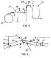
- Fig. 4 is a schematic view detailing features of the supply web section of the present invention;
- Fig. 5 is a schematic top view of features of the supply web illustrated in Fig. 4;
- Fig. 6 is an isolated view of a gimballed roller in accordance with the present invention;
- Fig. 7 is a schematic view of the take-up section of the present invention;
- Fig. 8 is a schematic top view of the take-up section of Fig. 7;
- Fig. 9 is an isolated view of a castered roller in accordance with the present invention; and
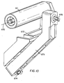
- Fig. 10 is a isolated view of a castered and gimballed roller in accordance with the present invention.
-
- Referring now to the drawings, wherein like references numerals designate identical or corresponding parts throughout the several view, Fig. 1 is an overall view of a
printing apparatus 15 in accordance with the present invention. As illustrated in Fig. 1,printing apparatus 15 comprises amedia supply section 17 and a media take-up section 19.Media supply section 17 is adapted to accommodate a plurality of media supply cassettes 17a-17c, while media take-up section 19 is adapted to accommodate a plurality of media take-up cassettes 19a-19c. As illustrated in Figs. 1-3, supply cassettes 17a-17c and take-up cassettes 19a-19c are wheel cassettes, which facilitate the interaction between the cassettes and the corresponding supply section and take-out sections (17, 19), however, the invention is not limited thereto, and the cassettes do not have to be wheeled cassettes. - On the supply side, supply cassettes 17a-17c can each contain a
roll 23 of, for example, photosensitive media that is to be processed through aprinting section 21. Take-up cassettes 19a-19c on the take-up side are initially empty and each include ashaft 90 adapted to receive a roll of photosensitive media after the web has past throughprinting section 21. - As illustrated in the view of Figs. 1 and 2, supply cassettes 17a-17c and take-up cassettes 19a-19c are provided at three locations and are angularly positioned with respect to each other. However, the invention is not limited thereto, and the cassettes can be located at various angles, while the printing apparatus can include more than three or less than three cassettes at each of the supply and take-up sides.
- Referring to Fig. 3 which illustrates a side view of
printing apparatus 15, it noted that supply cassette 17a which is seen in the view of Fig. 3 includessupply roll 23 of media such as, for example, photosensitive media.Supply section 17 includes a plurality of entry openings orports 25 which mate with a corresponding port or opening in supply cassettes 17a-17c to permit aweb 100 of photosensitive material to enter intosupply section 17. Only oneentry port 25 is illustrated in Fig. 3. It is recognized thatsupply section 17 includesentry ports 25 corresponding in number and location with a respective supply cassette 17a-17c. - Provided within
supply section 17 is atransport assembly 27 which is rotatable to a plurality of positions to mate with each of themedia entry ports 25 which correspond to each of thesupply cassettes transport assembly 27, where a further arrangement ofdrive rollers 33 transport the web of photosensitive material throughtransport assembly 27. As indicated above,transport assembly 27 is rotatable between each of theentry ports 25 so as to selectively accept media from each of thesupply cassettes transport mechanism 27 is simply pivoted or rotated aboutpoint 29 to the next appropriate position having a cassette (17a, 17b, 17c) with a supply of photosensitive material. - A feature of the present invention with respect to the
rotatable transport assembly 27 is the creation of a vertical twist at an angle of between 0-90 degrees and preferably approximately ± 30 degrees about a vertical axis in the photosensitive web. More specifically, as illustrated in Figs. 2-6,transport assembly 27 includes aroller 35 which is gimballed. Referring to Fig. 6 which illustrates one mounting example forgimballed roller 35, it is seen thatroller 35 can be mounted on a roller support 35a so as to be rotatable with respect totransport assembly 27 about alongitudinal axis 35b of a mediaspan approaching roller 35. This is one example of mounting a roller in a gimballed manner and it is recognized that other methods of mounting a roller in a gimballed manner are possible within the context of the present invention. This arrangement creates a first web span of media which extends fromsupply roll 23 to gimballedroller 35. With the arrangement of the present invention, as shown in Fig. 5, alateral position 110 of the span of media fromsupply roll 23 to gimballedroller 35 is derived bysupply roll 23, while anangular position 115 of the media fromsupply roll 23 to thegimballed roller 35 is derived bygimballed roller 35. As further illustrated in Figs. 4 and 5,supply section 17 includes a guiding shoe orplate 37, which helps guide the photosensitive material towardgimballed roller 35. - With the arrangement of the present invention, and as illustrated in, for example, Fig. 2, when the media is being first supplied from cassette 17a,
gimballed roller 35 will pivot to accommodate the twisting of the web.Gimballed roller 35 guides the web or material through an approximately 90 degree bend and then in an upward vertical direction intoprinting section 21 as illustrated in Figs. 2-4.Printing section 21 can include a guiding plate or shoe 39 (Fig. 4) which changes the conveying direction of the web, and a drive andpressure roller arrangement 41. Therefore, the span of the photosensitive material betweenroller 35 and drive andpressure roller arrangement 41 defines a second span of the photosensitive material passing throughprinting apparatus 15. With the arrangement of the present invention,gimballed roller 35 essentially acts as a hinge between the span of photosensitive material betweensupply roll 23 andgimballed roller 35, and the span of photosensitive material betweengimballed roller 35 and drive andpressure roller arrangement 41. This is conceptually illustrated in Fig. 5 of the application.Gimballed roller 35 which rotates as a unit withtransport assembly 27 will pivot with respect to transportassembly 27 in accordance with the twist of the web betweenroller 35 andplate 39 astransport assembly 27 is rotated between supply cassettes 17a-17c. -
Printing section 21 can be part of a known laser printer. However, the present invention is not limited thereto and other types of printing systems are possible within the context of the present invention. After the photosensitive web enters printingsection 21, as illustrated more particularly in Fig. 3, the material can sequentially pass through afirst slack loop 43, through a paper punching/markingsection 45, through asecond slack loop 47, over aprint drum 49 where the material can be laser scanned in accordance with image information (obtained separately by scanning a processed film, strip), through athird slack loop 51 and into take-upsection 19. - Like
supply section 17, take-upsection 19 includes a pivotable or rotatable transport or take-upassembly 53 which is rotatable aboutpoint 55, so as to be in mating engagement with a corresponding media exit opening orports 57 provided on the take-upsection 19. As described with reference to supplysection 17, take-upsection 19 includes the plurality ofexit openings 57 which correspond in number and location with take-upcassettes cassettes openings 57, so that the web of photosensitive material is supplied directly to the take-up cassettes. When a take-up cassette (19a, 19b, 19c) is full of exposed material,transport assembly 53 is rotated aboutpoint 55 to the next take-up cassette (19a, 19b, 19c). - Referring particularly to Fig. 7, at the exit area of
printing section 21, a combination of a shoe orplate 59 and alateral guide 61 is provided to guide the web towards the exit ofprinting section 21. At the exit ofprinting section 21, agimballed roller 63 is provided.Roller 63 guides the web through an approximately 90 degree bend and is mounted as previously described with respect togimballed roller 35 and illustrated in Fig. 6. After the media passes overgimballed roller 63, it is conveyed in a substantially vertical direction within take-outsection 19, and to rotatable transport or take-upassembly 53.Rotatable transport assembly 53 includes acastered roller 65 and a castered andgimballed roller 67. The specifics ofcastered roller 65 are illustrated in Fig. 9. As shown in Fig. 9,castered roller 65 is pivotally mounted onlinks 65a which pivot aboutpoints support 652. The axes oflinks 65a intersect at apoint 654 which defines an upstream pivot or caster axis forroller 65. Thus,roller 65 rotates aboutrotational axis 653 and due to the interaction oflinks 65a rotates about an axis throughpoint 654 which is spaced from and perpendicular torotational axis 653. This enablesroller 65 to self-align to the web. - Castered and
gimballed roller 67 is illustrated in detail in Fig. 10. As shown in Fig. 10,roller 67 is mounted on asupport 672 so as to be rotatable aboutrotational axis 670.Roller 67 andsupport 672 are mounted as a unit on afurther support 673 such thatroller 67 andsupport 672 pivot as a unit about pivot point orcaster axis 674 relative tofurther support 673.Pivot point 674 is spaced from and perpendicular torotational axis 670.Roller 67 is further rotatable as a unit relative to transportassembly 53 about pivot point orgimbal axis 675 which extends along a longitudinal axis of a media span atroller 67. Figures 9 and 10 respectively illustrate examples of mounting rollers in a castered and castered and gimballed manner. It is recognized that the present invention is not limited thereto and that other methods of mounting the rollers in a castered and castered and gimballed manner are possible within the context of the present invention. - With the arrangement as illustrated in Fig. 7, as the web is vertically led in a downward direction from
roller 63 toroller 65, based on the position oftransport assembly 53, for example, when feeding photosensitive material to eithercassettes 19c or 19a, the web is twisted at a specific angle. - After being conveyed by castered and
gimballed roller 67, which self-align to the web, the web can be upwardly conveyed to a shoe andlateral guide arrangement 69, and thereafter fed by feedingroller 71 to an appropriate take-up cassette 19a-19c. - In a feature of the present invention, a third span of the photosensitive material is defined between
lateral guide 61 andgimballed roller 63 In this span, as illustrated in Fig. 8, alateral position 300 is derived bylateral guide 61, while anangular position 303 is derived fromgimballed roller 63. A further span is defined betweenguide arrangement 69 and take-up roll 90. In this further span, alateral position 305 is derived fromguide arrangement 69, while anangular position 307 is derived from take-up roll 90 in take-up cassette (19a-19c). Therefore, as conceptually illustrated in Fig. 8, the span of the web fromroller 63 to guidearrangement 69 essentially acts as a hinge astransport assembly 53 rotates, which permits the feeding of photosensitive material without appreciable lateral tracking of the photosensitive material. Essentially,roller 67 is castered and gimballed so as to act as a hinge and provide zero constraint, whileroller 67 is castered so as to provide zero constraint. - Thus, as
transport assembly 53 rotates between take-up cassettes 19a-19c, the web will be twisted about a vertical axis at an angle of between 0 and 90 degrees, for example, at an angle of ± 30 degrees betweenroller 63 androller 65, which pivot relative to transportassembly 53 to accommodate the twisting while minimizing web tracking variation. In a further feature of the present invention, and referring specifically to the supply side and more specifically to transportassembly 27 atsupply section 17, as illustrated in Figs. 3 and 4, asplicer 75 is provided onrotatable transport assembly 27. Thus,splicer 75 andgimballed roller 35 are rotatable as a unit together withtransport assembly 27. The arrangement of the present invention permitssplicer 75 to be pivotable from one cassette 17a to anothercassette 17b to afurther cassette 17c. This provides for a straight thrust of the web from each cassette (17a-17c) such that the span from the supply cassette (17a-17c) is always straight. - Further, the web can be twisted about vertical axis 500 (Fig. 4) between
gimballed roller 35 and plate orshoe 39 without appreciable tracking error because the web is two dimensionally stiff at twist angles of less than 90 degrees.Splicer 75 serves to splice the end of the material from an empty cassette to begin the paper of a next full cassette. With reference to the diagrams of Figs. 5 and 8,reference numeral 83 schematically illustrates the twisted web span entering theprinting section 21, whilereference numeral 85 schematically illustrates the twisted web span exiting theprinting section 21. Each of the web spans are respectively twisted about vertical axis 500 (Fig. 4) and vertical axis 501 (Fig. 7). - In a further feature of the present invention, and specifically relating to take-up
section 19 and more specifically to transportassembly 53, a knowncutter 77 is provided ontransport assembly 53.Cutter 77 along withcastered roller 65 and castered andgimballed roller 67 are rotatable as a unit withtransport assembly 53. The cutter is utilized on the take-up side to cut the paper an appropriate length, at the termination of the roll. Thereafter,transport assembly 53 can be rotated to the next empty take-up cassette (19a- 19c). - Control of
rotatable transport assemblies printing apparatus 15, which control a moving mechanism such as a motor and are responsive to signals with respect to, for example, the amount of paper in the cassettes, the position of the web, etc. For example, a supply cassette can include sensors which communicate with sensors within the printing section, to indicate when a supply cassette is empty or full, and similarly, a take-up cassette can include sensors to indicate the amount of paper in the take-up cassette. As a further feature, a sensor such as a counter can be provided along the web path, to count the amount of paper, and utilize this as a reference with respect to the amount of paper within a specific cassette. - Accordingly, the present invention provides for a printing apparatus that permits a connection of a plurality of supply and take-up cassettes through a controlled path geometry and controlled constraints. The web path through the printing apparatus undergoes two approximately 90° bends at each end. At each pair of bends the web is pivoted and undergoes a twist about a vertical line or a line which is colinear to the pivot axis. This pivot motion permits the web to be routed to and from a plurality of supply and take-up cassettes so as to merge multiple paper paths into one central path. The pivot motion also creates straight feed paths to a splicer and from a cutter and eliminates the need for a complex shuttle mechanism or complicated paper handling.
Claims (10)
- A printing apparatus (15) comprising:a media supply section (17) having a transport assembly (27) and a plurality of media entry openings (25), said transport assembly being rotatable to each of said media entry openings so as to accept media from a selected one of said media entry openings;a printing section (21) adapted to accept media from the media supply section; anda take-up section (19) which is adapted to receive media from the printing section, said take-up section comprising a take-up assembly (53) and a plurality of media exit openings, said take-up assembly being rotatable to each of said media exit openings so as to discharge media through a selected one of said media exit openings.
- A printing apparatus according to claim 1, wherein said transport assembly comprises a splicing assembly and a first roller which is rotatable, with respect to said transport assembly, about a longitudinal axis of media approaching said first roller, said splicing assembly and said roller being further rotatable as a unit together with said transport assembly.
- A printing apparatus according to claim 1, further comprising at least one media supply cassette having a media supply roll therein and positioned at one of said media entry openings to supply media to said supply section.
- A printing apparatus according to claim 2, further comprising at least one media supply cassette having a media supply roll therein and positioned at one of said media entry points to supply media to said supply section, such that a first media span for a media path through said printing apparatus is defined between said media supply roll and said first roller.
- A printing apparatus comprising:a media supply section comprising a first transport assembly which conveys media along a first transport assembly longitudinal axis, said first transport assembly being rotatable between a plurality of supply entry ports on said media supply section to selectively accept media from each of said supply entry ports, said first transport assembly further comprising at least one first roller which is rotatable with respect to said first transport assembly about said first transport assembly longitudinal axis; anda printing section which receives media from said media supply section, said printing section comprising a first guide plate which guides media from said at least one first roller into said printing section, said first transport assembly being rotatable to least one position which creates a twist in a media span of said media between said at least one first roller and said first guide plate.
- A printing apparatus according to claim 5, wherein said printing section comprises at least one second roller which is rotatable about a longitudinal axis of a media span approaching the at least one second roller.
- A media supply assembly comprising:a plurality of media entry ports;a transport assembly which is rotatable to each of said media entry ports to receive and convey media entering through said media entry ports along a longitudinal axis; andat least one roller mounted on said transport assembly so as to be rotatable about said longitudinal axis, said at least one roller conveying media along said transport assembly toward an exit port of said media supply assembly.
- A media take-up assembly comprisinga media entry port for receiving media therein;a plurality of media exit ports;a transport assembly which conveys media from said media entry port to one of said media exit ports, said transport assembly being rotatable to each of said media exit ports; andat least one first roller mounted on said transport assembly so as to rotate about a pivot point which is spaced from a rotational axis of said at least one first roller.
- A media take-up assembly according to claim 8, further comprising at least one second roller mounted downstream of said at least one first roller, said at least one second roller being adapted to rotate about a pivot point spaced from a rotational axis of said at least one second roller and rotate with respect to said transport assembly about a longitudinal axis of a media span between said at least one first roller and said at least one second roller.
- A printing apparatus comprising:a rotatable transport assembly provided at least at one of an input side or output side of a printing section, said transport assembly being adapted to twist a web of photosensitive media about a vertical axis as said photosensitive media is conveyed through said printing apparatus.
Applications Claiming Priority (2)
| Application Number | Priority Date | Filing Date | Title |
|---|---|---|---|
| US418230 | 1999-10-14 | ||
| US09/418,230 US6227731B1 (en) | 1999-10-14 | 1999-10-14 | Printing apparatus |
Publications (2)
| Publication Number | Publication Date |
|---|---|
| EP1096309A1 true EP1096309A1 (en) | 2001-05-02 |
| EP1096309B1 EP1096309B1 (en) | 2004-01-14 |
Family
ID=23657242
Family Applications (1)
| Application Number | Title | Priority Date | Filing Date |
|---|---|---|---|
| EP00203429A Expired - Lifetime EP1096309B1 (en) | 1999-10-14 | 2000-10-03 | A photographic printing apparatus with a web transport assembly for plural media supplies/take-ups |
Country Status (4)
| Country | Link |
|---|---|
| US (2) | US6227731B1 (en) |
| EP (1) | EP1096309B1 (en) |
| JP (1) | JP2001146348A (en) |
| DE (1) | DE60007706T2 (en) |
Cited By (2)
| Publication number | Priority date | Publication date | Assignee | Title |
|---|---|---|---|---|
| EP1267302A3 (en) * | 2001-05-25 | 2006-11-02 | Eastman Kodak Company | Media width detecting system for an imaging apparatus |
| CN111231466A (en) * | 2020-01-14 | 2020-06-05 | 浙江绿禾生态科技股份有限公司 | Degradable biodegradable film and preparation method thereof |
Families Citing this family (15)
| Publication number | Priority date | Publication date | Assignee | Title |
|---|---|---|---|---|
| US6227731B1 (en) * | 1999-10-14 | 2001-05-08 | Eastman Kodak Company | Printing apparatus |
| DE19960649B4 (en) * | 1999-12-16 | 2011-06-22 | Goss Contiweb B.V. | Device for correcting the lateral position of a printing material web in a web-fed rotary printing press |
| USD490460S1 (en) | 2002-02-01 | 2004-05-25 | Datacard Corporation | Front panel and hood of a module of a card personalization system |
| CN1578614B (en) * | 2003-06-30 | 2010-04-21 | 山洋电气株式会社 | Axial fan unit and heating element cooling unit |
| US7295289B2 (en) * | 2003-07-11 | 2007-11-13 | Baker Hughes Incorporated | Continuous paper feed system |
| US7478895B2 (en) | 2003-12-05 | 2009-01-20 | Eastman Kodak Company | Backprinting assembly for a photographic printer |
| US8052832B2 (en) * | 2005-06-07 | 2011-11-08 | Sony Corporation | Splicing assembly and method |
| US20070210502A1 (en) * | 2006-03-09 | 2007-09-13 | Gamsky Joseph E | Apparatus For Handling Rolled Material |
| JP5280235B2 (en) * | 2009-02-05 | 2013-09-04 | 株式会社セイコーアイ・インフォテック | Recording method |
| US20110128337A1 (en) * | 2009-11-30 | 2011-06-02 | Muir Christopher M | Media transport system for non-contacting printing |
| US20110278389A1 (en) * | 2010-05-12 | 2011-11-17 | Armbruster Randy E | Media transport system drive module |
| JP5776875B2 (en) * | 2011-02-15 | 2015-09-09 | セイコーエプソン株式会社 | Recording device |
| EP2765460A1 (en) * | 2013-02-07 | 2014-08-13 | Xeikon IP BV | Image application unit for use with liquid toner and digital printing unit comprising same |
| JP5980750B2 (en) * | 2013-09-13 | 2016-08-31 | 株式会社ミヤコシ | Label paper processing equipment |
| US10239726B2 (en) | 2016-06-15 | 2019-03-26 | Dynamex Corporation | Ribbon self-orienting device for traversed rolls |
Citations (7)
| Publication number | Priority date | Publication date | Assignee | Title |
|---|---|---|---|---|
| US4091979A (en) * | 1976-03-29 | 1978-05-30 | Bell & Howell Company | Methods and apparatus for precision guiding a web |
| US4919354A (en) * | 1987-11-06 | 1990-04-24 | Agfa-Gevaert Aktiengesellschaft | Apparatus for replacing rolls of customer films in copying machines |
| JPH0511357A (en) * | 1991-05-01 | 1993-01-22 | Fuji Photo Film Co Ltd | Photographic film guiding device |
| US5335045A (en) * | 1992-05-22 | 1994-08-02 | Gretag Imaging Ag | Photographic printing machine for copying originals on sheet-like copy material |
| US5337118A (en) * | 1991-11-20 | 1994-08-09 | Gretag Imaging Ag | Photographic copying apparatus and process of operation |
| US5436688A (en) * | 1992-10-30 | 1995-07-25 | Fuji Photo Film Co., Ltd. | Automatic photofinishing apparatus |
| US5553808A (en) * | 1993-07-09 | 1996-09-10 | Eastman Kodak Company | Feeding of a machine with a turret supporting removable magazines distributing strips by means of an external source |
Family Cites Families (28)
| Publication number | Priority date | Publication date | Assignee | Title |
|---|---|---|---|---|
| US4008957A (en) | 1975-05-27 | 1977-02-22 | Xerox Corporation | Reproduction machine control |
| IT7920640U1 (en) | 1979-01-29 | 1980-07-29 | Falomo Lodovico | DEVICE FOR SIMULTANEOUS TRANSFER OF PHOTOGRAPHIC PAPER IN STRIPS FROM ROLL CASSETTES TO DEVELOPERS. |
| DE2923469A1 (en) | 1979-06-09 | 1980-12-11 | Olympia Werke Ag | Photocopier with copy supply in roll form - has several rolls on pivoting carrier with ratchet location |
| US4421228A (en) * | 1981-08-17 | 1983-12-20 | Eastman Kodak Company | Periodically aligning an endless web |
| DE3150495A1 (en) | 1981-12-19 | 1983-06-30 | Agfa-Gevaert Ag, 5090 Leverkusen | CASSETTE FOR WINDING AND UNWINDING PHOTOGRAPHIC MATERIAL IN TAPE SHAPE |
| IT1188062B (en) * | 1985-11-19 | 1987-12-30 | Pittacus Sa | DISTRIBUTOR FOR THE AUTOMATIC FEEDING OF FILMS OF DIFFERENT CHARACTERISTICS TO A PACKAGING MACHINE |
| DE3609086A1 (en) * | 1986-03-18 | 1987-10-01 | Wifag Maschf | DEVICE FOR BE- OR. UNLOADING A ROLLING STAND OF A ROLLING ROTATION PRINTING MACHINE WITH OR OF PAPER ROLLS |
| US4878067A (en) | 1986-04-22 | 1989-10-31 | Minolta Camera Kabushiki Kaisha | Laser recorder with stable film feed auxiliary scanning |
| US4814793A (en) | 1986-04-22 | 1989-03-21 | Minolta Camera Kabushiki Kaisha | Film handling means for a laser recorder |
| US4725050A (en) * | 1986-07-22 | 1988-02-16 | Tokyo Kikai Seisakusho | Multi-section folding apparatus for rotary press |
| DE3713171C2 (en) | 1987-04-17 | 1995-12-14 | Agfa Gevaert Ag | Photographic device for processing photographic material that can be accommodated in mobile cassettes |
| US4891653A (en) | 1987-04-27 | 1990-01-02 | Minolta Camera Kabushiki Kaisha | Image recorder with microstep driven motor transport |
| US4996541A (en) | 1989-04-19 | 1991-02-26 | Minolta Camera Kabushiki Kaisha | Film conveying apparatus |
| JP2638291B2 (en) * | 1990-11-26 | 1997-08-06 | 三田工業株式会社 | Paper transport joint mechanism |
| US5368285A (en) * | 1991-02-28 | 1994-11-29 | Canon Kabushiki Kaisha | Automatic sheet feeding apparatus |
| DE59107083D1 (en) | 1991-06-24 | 1996-01-25 | Gretag Imaging Ag | Photographic copier |
| DE4141895C2 (en) | 1991-12-18 | 1995-03-30 | Agfa Gevaert Ag | Method and device for positioning the tail of a trailing belt |
| JPH08451B2 (en) * | 1992-07-22 | 1996-01-10 | 株式会社東京機械製作所 | Rotary press and paper feeding unit of the rotary press |
| CA2075880A1 (en) * | 1992-08-12 | 1994-02-13 | Shigehiro Hano | Electrophotographic apparatus and method |
| IT1258093B (en) | 1992-12-15 | 1996-02-20 | San Marco Imaging Srl | DEVICE APPLICABLE IN THE PHOTOGRAPHIC FIELD ON PRINTING MACHINES FOR THE ADVANCE AND POSITIONING IN THE PRINTING STATION OF SLICES OF VARIOUS SIZES OF PHOTOSENSITIVE PAPER TAPES OF VARIOUS SIZES AND THEIR SUBSEQUENT SENDING TO THE NEXT DEVICE. |
| US5326093A (en) * | 1993-05-24 | 1994-07-05 | Xerox Corporation | Universal interface module interconnecting various copiers and printers with various sheet output processors |
| DE59309909D1 (en) | 1993-06-17 | 2000-01-27 | Gretag Imaging Ag | Winding spool for band-shaped photographic material |
| JP3239323B2 (en) | 1993-08-04 | 2001-12-17 | 富士写真フイルム株式会社 | Photosensitive material processing equipment |
| US5397289A (en) * | 1993-09-28 | 1995-03-14 | Eastman Kodak Company | Gimballed roller for web material |
| US5558263A (en) * | 1994-07-26 | 1996-09-24 | Eastman Kodak Company | Apparatus and method for non-contact active tensioning and steering of moving webs |
| IT1280161B1 (en) | 1995-04-19 | 1998-01-05 | San Marco Imaging Srl | PHOTOGRAPHIC PRINTER AND RELATED PRINTING PROCEDURE |
| FR2766472B1 (en) * | 1997-07-22 | 1999-10-29 | Heidelberger Druckmasch Ag | BACKUP DEVICE IN THE EVENT OF PAPER WEB BREAKAGE IN A ROTARY PRINTING MACHINE IN OPERATION |
| US6227731B1 (en) * | 1999-10-14 | 2001-05-08 | Eastman Kodak Company | Printing apparatus |
-
1999
- 1999-10-14 US US09/418,230 patent/US6227731B1/en not_active Expired - Fee Related
-
2000
- 2000-10-03 DE DE60007706T patent/DE60007706T2/en not_active Withdrawn - After Issue
- 2000-10-03 EP EP00203429A patent/EP1096309B1/en not_active Expired - Lifetime
- 2000-10-12 JP JP2000312304A patent/JP2001146348A/en active Pending
-
2001
- 2001-04-05 US US09/826,653 patent/US6435743B2/en not_active Expired - Fee Related
Patent Citations (7)
| Publication number | Priority date | Publication date | Assignee | Title |
|---|---|---|---|---|
| US4091979A (en) * | 1976-03-29 | 1978-05-30 | Bell & Howell Company | Methods and apparatus for precision guiding a web |
| US4919354A (en) * | 1987-11-06 | 1990-04-24 | Agfa-Gevaert Aktiengesellschaft | Apparatus for replacing rolls of customer films in copying machines |
| JPH0511357A (en) * | 1991-05-01 | 1993-01-22 | Fuji Photo Film Co Ltd | Photographic film guiding device |
| US5337118A (en) * | 1991-11-20 | 1994-08-09 | Gretag Imaging Ag | Photographic copying apparatus and process of operation |
| US5335045A (en) * | 1992-05-22 | 1994-08-02 | Gretag Imaging Ag | Photographic printing machine for copying originals on sheet-like copy material |
| US5436688A (en) * | 1992-10-30 | 1995-07-25 | Fuji Photo Film Co., Ltd. | Automatic photofinishing apparatus |
| US5553808A (en) * | 1993-07-09 | 1996-09-10 | Eastman Kodak Company | Feeding of a machine with a turret supporting removable magazines distributing strips by means of an external source |
Non-Patent Citations (1)
| Title |
|---|
| PATENT ABSTRACTS OF JAPAN vol. 017, no. 273 (P - 1545) 26 May 1993 (1993-05-26) * |
Cited By (2)
| Publication number | Priority date | Publication date | Assignee | Title |
|---|---|---|---|---|
| EP1267302A3 (en) * | 2001-05-25 | 2006-11-02 | Eastman Kodak Company | Media width detecting system for an imaging apparatus |
| CN111231466A (en) * | 2020-01-14 | 2020-06-05 | 浙江绿禾生态科技股份有限公司 | Degradable biodegradable film and preparation method thereof |
Also Published As
| Publication number | Publication date |
|---|---|
| DE60007706T2 (en) | 2004-12-02 |
| US6227731B1 (en) | 2001-05-08 |
| JP2001146348A (en) | 2001-05-29 |
| US20010010774A1 (en) | 2001-08-02 |
| US6435743B2 (en) | 2002-08-20 |
| DE60007706D1 (en) | 2004-02-19 |
| EP1096309B1 (en) | 2004-01-14 |
Similar Documents
| Publication | Publication Date | Title |
|---|---|---|
| EP1096309B1 (en) | A photographic printing apparatus with a web transport assembly for plural media supplies/take-ups | |
| US5467179A (en) | Turnover device for a web-shaped recording medium | |
| US5947617A (en) | Skew correction mechanism for a roll paper | |
| US5092573A (en) | Auxiliary paper feeding apparatus for high speed computer printers | |
| US4843430A (en) | Apparatus for processing photosensitive material from mobile cassettes | |
| US5579099A (en) | Document conveying device and document reading device operable therewith | |
| US5384619A (en) | Image forming apparatus having re-feeding unit | |
| JP3464831B2 (en) | Magnetic ticket reader | |
| AU610209B2 (en) | Device for feeding several paper webs to a printer | |
| US4475677A (en) | Transport apparatus for conveying a perforated recording medium to a _platen or the like | |
| US6239864B1 (en) | Image forming apparatus with a paper positioning device | |
| EP0311821B1 (en) | Device for transporting documents | |
| US5018889A (en) | Sheet conveying apparatus for a printer | |
| JP2002193510A (en) | Device for generating gap of carried flexible flat article | |
| JPS60102362A (en) | Sheet feeder | |
| KR100208115B1 (en) | Film winder | |
| JPH11263467A (en) | Money conveying device | |
| US6026948A (en) | Conveying and feeding method and apparatus for film in a film cartridge | |
| EP0829751A2 (en) | A photographic processor comprising a picture detecting sensor and a notcher for frame positioning | |
| US5966198A (en) | Printer/processor | |
| US11924388B2 (en) | Image recording apparatus and feed tray that includes a side guide inside a pair of sidewalls for roll paper | |
| JP2864487B2 (en) | Passbook handling device | |
| JP7645105B2 (en) | Hoop material connection device | |
| EP1199875A2 (en) | Original sheet reading apparatus | |
| JP3533731B2 (en) | Printer |
Legal Events
| Date | Code | Title | Description |
|---|---|---|---|
| PUAI | Public reference made under article 153(3) epc to a published international application that has entered the european phase |
Free format text: ORIGINAL CODE: 0009012 |
|
| AK | Designated contracting states |
Kind code of ref document: A1 Designated state(s): DE FR GB |
|
| AX | Request for extension of the european patent |
Free format text: AL;LT;LV;MK;RO;SI |
|
| 17P | Request for examination filed |
Effective date: 20011010 |
|
| 17Q | First examination report despatched |
Effective date: 20011206 |
|
| AKX | Designation fees paid |
Free format text: DE FR GB |
|
| GRAP | Despatch of communication of intention to grant a patent |
Free format text: ORIGINAL CODE: EPIDOSNIGR1 |
|
| GRAS | Grant fee paid |
Free format text: ORIGINAL CODE: EPIDOSNIGR3 |
|
| GRAA | (expected) grant |
Free format text: ORIGINAL CODE: 0009210 |
|
| AK | Designated contracting states |
Kind code of ref document: B1 Designated state(s): DE FR GB |
|
| REG | Reference to a national code |
Ref country code: GB Ref legal event code: FG4D |
|
| REF | Corresponds to: |
Ref document number: 60007706 Country of ref document: DE Date of ref document: 20040219 Kind code of ref document: P |
|
| ET | Fr: translation filed | ||
| PLBE | No opposition filed within time limit |
Free format text: ORIGINAL CODE: 0009261 |
|
| STAA | Information on the status of an ep patent application or granted ep patent |
Free format text: STATUS: NO OPPOSITION FILED WITHIN TIME LIMIT |
|
| 26N | No opposition filed |
Effective date: 20041015 |
|
| PGFP | Annual fee paid to national office [announced via postgrant information from national office to epo] |
Ref country code: GB Payment date: 20050914 Year of fee payment: 6 |
|
| PGFP | Annual fee paid to national office [announced via postgrant information from national office to epo] |
Ref country code: FR Payment date: 20051006 Year of fee payment: 6 |
|
| PGFP | Annual fee paid to national office [announced via postgrant information from national office to epo] |
Ref country code: DE Payment date: 20051031 Year of fee payment: 6 |
|
| PG25 | Lapsed in a contracting state [announced via postgrant information from national office to epo] |
Ref country code: DE Free format text: LAPSE BECAUSE OF THE APPLICANT RENOUNCES Effective date: 20060221 |
|
| GBPC | Gb: european patent ceased through non-payment of renewal fee |
Effective date: 20061003 |
|
| REG | Reference to a national code |
Ref country code: FR Ref legal event code: ST Effective date: 20070629 |
|
| PG25 | Lapsed in a contracting state [announced via postgrant information from national office to epo] |
Ref country code: GB Free format text: LAPSE BECAUSE OF NON-PAYMENT OF DUE FEES Effective date: 20061003 |
|
| PG25 | Lapsed in a contracting state [announced via postgrant information from national office to epo] |
Ref country code: FR Free format text: LAPSE BECAUSE OF NON-PAYMENT OF DUE FEES Effective date: 20061031 |