BACKGROUND OF THE INVENTION
Field of the Invention
The present invention relates to an optical
apparatus and an optical apparatus driving unit adapted
for use in a television camera, a video camera system
or the like, and more particularly to a zoom lens
apparatus adapted for use in an ENG camera system and a
driving unit therefor.
Related Background Art
The zoom drive control utilizing a zoom control
switch or a zoom demand in an optical apparatus such as
the conventional zoom lens or video lens is disclosed
for example in the Japanese Patent Application Laid-open
No. 51-40924.
Such zoom drive control is achieved by servo means
consisting of a drive system such as a motor and a
control system for controlling the function of the
drive system, and a zoom control switch or a zoom
demand is utilized for providing the control system of
such servo means with a command signal. In the actual
zooming operation, the zooming speed can be adjusted
from a low speed to a high speed as desired by the
operator, by the amount of manipulation of the zoom
control switch or a thumb ring provided in the zoom
demand.
In the image taking operation with the television
camera or the video camera, there are employed various
image taking techniques and various functions are
proposed for realizing such image taking techniques in
a simpler and exact manner.
Among such functions, there is known a position
preset drive control function, in which an arbitrary
zoom position is memorized in advance as a preset
position, and the optical system of the zoom lens is
moved to such preset position by turning on a preset
zoom switch in the course of an image taking operation.
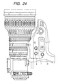
Such function will be explained with reference to
Fig. 24 which is an upper external view of a zoom lens
for use in an ENG camera and Fig. 25 which is a lateral
external view thereof.
As shown in Figs. 24 and 25, on a lens-barrel
portion (main body portion) of the zoom lens for the
ENG camera, there is mounted a lens drive unit 31
incorporating therein motors for electrical zooming,
focusing and iris control, position sensors, control
circuits etc.
The drive unit 31 is also provided with a zoom
control switch 1 for controlling the electrical
zooming, a zoom speed controlling variable resistor 3
for variably setting the drive speed of the zooming
optical system in relation to the manipulation amount
of the zoom control switch 1, a memory switch 8 for
instructing the memory of the preset position of the
zoom lens, and a preset zoom switch 7 for instructing
the start of the preset operation.
In the following there will be explained the
setting of the preset position and the presetting
operation in the actual use of the preset function.
The setting of the preset position is executed by
the operator by moving the zoom lens to a desired
preset position and turning on the memory switch 8,
whereby the position of the zoom lens in such state is
memorized as a preset position.
Also the preset operation is executed by the
operator by turning on the preset zoom switch 7,
whereby the zoom lens is electrically driven to the
present position. The drive speed of the zoom lens in
this operation is determined by the set position of the
zoom speed controlling variable resistor 3.
The above-described conventional drive unit 31 is
however associated with the following drawbacks, since
the drive speed of the zoom lens in the preset
operation is determined by the set position of the zoom
speed controlling variable resistor 3, which variably
setting the drive speed of the zoom lens in relation to
the manipulation amount of the zoom control switch 1.
For example in case the operator wishes to execute
the zoom lens drive with the maximum speed in case of
operation with the zoom control switch 1 but with a
medium speed in the preset operation, it is necessary
to set the zoom speed controlling variable resistor 3
at the maximum speed during the manipulation of the
zoom control switch 1, then to change the setting of
the zoom speed controlling variable resistor 3 to a
medium speed prior to the start of the preset
operation, and to set the zoom speed controlling
variable resistor 3 again at the maximum speed after
the preset operation is completed.
Also the operability of the zoom control switch 1
may be deteriorated if the lower limit of the setting
of the zoom speed controlling variable resistor 3 is
selected excessively low. For this reason, the lower
limit of setting of the zoom speed controlling variable
resistor 3 is inevitably limited, so that the drive
speed of the zoom lens in the preset operation cannot
be made very low.
On the other hand, in taking the image with the
television camera or the video camera, there is known a
technique of taking the image while executing zooming
at a constant low speed. Such image taking technique
may be utilized repeatedly in the course of image
taking.
Such zooming operation has been achieved by
maintaining a constant manipulation amount of the zoom
control switch or the thumb ring provided in the zoom
demand.
It is however not easy for the operator to
maintain such constant manipulation amount of the zoom
control switch or the like during the course of zooming
operation. Particularly, as the zoom drive speed
becomes lower, there is required a longer time for
maintaining the constant manipulation amount of the
zoom control switch etc., so that it is very difficult
to maintain the constant manipulation amount. It is
also difficult to repeatedly reproduce the same zoom
drive speed.
SUMMARY OF THE INVENTION
In consideration of the foregoing, a first
invention of the present application provides an
optical apparatus provided with an optical member or an
optical apparatus driving unit to be mounted on or
connected to the main body of the optical apparatus,
comprising:
Also a second invention of the present application
provides an optical apparatus provided with an optical
member or an optical apparatus driving unit to be
mounted on or connected to the main body of the optical
apparatus, comprising:
In a preferred embodiment, when the optical member
is driven and the memory instructing operation means is
operated, the control means causes the memory means to
memorize, as the preset speed information, the actual
drive speed of the optical member at the operation of
the memory instructing operation means.
In a preferred embodiment, there is provided drive
instructing operation means to be operated for
generating a drive speed command for the optical member
corresponding to an operation amount, and, when the
drive instructing operation means and the memory
instructing operation means are both operated, the
control means causes the memory means to memorize, as
the preset speed information, the drive speed command
at the operation of the memory instructing operation
means.
In a preferred embodiment, in the course of the
above-mentioned preset drive control, the control means
compares the actual drive speed of the optical member
with the drive speed corresponding to the preset speed
information, and increases or decreases the actual
drive speed of the optical member in such a manner that
the above-mentioned two speed substantially coincide.
In a preferred embodiment, there is provided
display means for displaying that the above-mentioned
preset drive control is being executed.
In a preferred embodiment, there is provided speed
selecting operation means to be operated for selecting
either the drive speed corresponding to the preset
speed information or a maximum drivable speed for the
drive speed of the optical member, and the control
means is adapted to drive the optical member with the
drive speed selected by the operation of the speed
selecting operation means.
In a preferred embodiment, there is provided
control starting operation means to be operated for
starting the above-mentioned preset drive control.
In a preferred embodiment, the control means is
adapted to interrupt the preset drive control in
response to an operation on the control starting
operation means in the course of the preset drive
control.
In a preferred embodiment, there is provided drive
instructing operation means to be operated for
generating a drive command for the optical member
according to at least either of the operation amount
and the operation direction, and the control means is
adapted to interrupt the preset drive control in
response to an operation of the drive instructing
operation means in the course of the preset drive
control.
In a preferred embodiment, there is provided
position detection means for detecting the actual drive
position of the optical member, and the control means
is adapted, in response to an operation of the memory
instructing operation means, to cause the memory means
to memorize, as the preset position information, the
actual drive position of the optical member detected by
the position detection means.
In a preferred embodiment, there is provided
control starting operation means to be operated for
starting the preset drive control, and, in response to
the operations of the memory instructing operation
means and the control starting operation means, the
control means is adapted to cause the memory means to
memorize, as the preset position information, the
actual drive position of the optical member detected by
the position detection means.
In a preferred embodiment, the control means is
adapted, in response to the operation of the control
starting operation means while the memory instructing
operation means is operated or simultaneously with the
operation thereof, to cause the memory means to
memorized, as the preset position information, the
actual drive position of the optical member detected by
the position detection means.
In a preferred embodiment, when the optical member
is driven and the memory instructing operation means is
operated, the control means is adapted to cause the
memory means to memorize, as the preset direction
information, the actual drive direction of the optical
member at the operation of the memory instructing
operation means.
In a preferred embodiment, there is provided drive
instructing operation means to be operated for
generating a drive direction command for the optical
member corresponding to the operating direction, and
the control means is adapted, when the drive
instructing operation means and the memory instructing
operation means are both operated, to cause the memory
means to memorize, as the preset direction information,
the drive direction command at the operation of the
memory instructing operation means.
In a preferred embodiment, there is provided a
camera system consisting of an optical apparatus
according to any of the foregoing embodiments, or an
optical apparatus driving unit according to any of the
foregoing embodiments and a main body of the optical
apparatus, and a camera on which such optical apparatus
is mounted.
BRIEF DESCRIPTION OF THE DRAWINGS
Fig. 1 is a view showing the configuration of a
lens apparatus constituting a first embodiment of the
present invention;
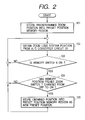
Fig. 2 is a memory setting flow chart for a preset
position to be employed in the preset memory position
zoom control in the above-mentioned lens apparatus;
Fig. 3 is a memory setting flow chart for a preset
speed to be employed in the preset memory position zoom
control in the above-mentioned lens apparatus;
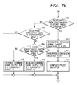
Fig. 4, which is comprised of Figs. 4A and 4B, and
Fig. 5 are process flow charts of the preset memory
position zoom control in the above-mentioned lens
apparatus;
Fig. 6 is a view showing the configuration of a
lens apparatus constituting a second embodiment of the
present invention;
Fig. 7, which is comprised of Figs. 7A and 7B, and
Fig. 8 are process flow charts of the preset memory
position zoom control in the second embodiment;
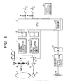
Fig. 9 is a view showing the configuration of a
lens apparatus constituting a third embodiment of the
present invention;
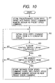
Fig. 10 is a memory setting flow chart for a
preset speed to be employed in the preset memory
position zoom control in the lens apparatus of the
third embodiment;
Figs. 11 and 12 are process flow charts in the
preset memory position zoom control in the lens
apparatus of the third embodiment;
Fig. 13 is a view showing the configuration of a
lens apparatus constituting a fourth embodiment of the
present invention;
Fig. 14 is a memory setting flow chart for a
preset speed and a preset direction to be employed in
the preset memory position zoom control in the above-mentioned
lens apparatus;
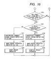
Fig. 15, which is comprised of Figs. 15A and 15B,
and Fig. 16 are process flow charts in the preset speed
zoom control in the above-mentioned lens apparatus;
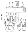
Fig. 17 is a view showing the configuration of a
lens apparatus constituting a fifth embodiment of the
present invention;
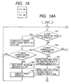
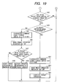
Fig. 18, which is comprised of Figs. 18A and 18B,
and Fig. 19 are process flow charts in the preset speed
zoom control in the lens apparatus of the fifth
embodiment;
Fig. 20 is a view showing the configuration of a
lens apparatus constituting a sixth embodiment of the
present invention;
Fig. 21 is a memory setting flow chart for a
preset speed (direction) to be employed in the preset
speed zoom control in the sixth embodiment;
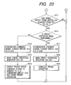
Figs. 22 and 23 are process flow charts in the
preset speed zoom control in the lens apparatus of the
sixth embodiment;
Fig. 24 is a plan view of a conventional lens
drive unit; and
Fig. 25 is a lateral view of a conventional lens
drive unit.
DETAILED DESCRIPTION OF THE PREFERRED EMBODIMENTS
[First embodiment]
Fig. 1 shows the configuration of a lens apparatus
(optical apparatus) constituting a first embodiment of
the present invention, wherein components equivalent in
function to those shown in Figs. 24 and 25 are
represented by symbols same as in Figs. 24 and 25.
A zoom control switch (instructing operation
means) 1 is to be operated by the photographer or
operator. A command signal generation circuit 2
generates a command signal for instructing a drive
direction and a drive speed (which may also be a drive
amount or a drive position) corresponding to the
operation amount of the zoom control switch 1 in order
to electrically drive a zooming optical system (optical
adjustment means) 9 for executing the zooming
adjustment of the lens apparatus.
A zoom speed controlling variable resistor 3
changes the drive speed of the zooming optical system 9
corresponding to the operation amount of the zoom
control switch 1. A command signal calculation circuit
4 executes signal level shifting on the command signal
for fetching in an A/D conversion circuit 5. An A/D
conversion circuit 5 converts the analog signal
outputted from the command signal calculation circuit 4
into a digital signal.
A CPU 6 controls the functions of the present lens
apparatus and is provided therein with a memory (memory
means) 6a capable of memorizing a preset position
(preset position information) and a preset speed
(preset speed information). The CPU 6 also executes
"preset memory position zoom control (preset
position/speed drive control)" for executing drive to
the preset position memorized in the memory 6a with the
memorized preset speed.
A memory switch (memory instructing operation
means) 8 is used for providing the CPU 6 with an
instruction for memory of the preset position and the
preset speed to be employed in the "preset memory
position zoom control".
A preset memory position zoom switch (control
starting operation means) 7 has a position memorizing
function for causing the memory 6a to memorized the
preset position upon being turned on after or
simultaneous with the turning-on of the memory switch
8, and a function of instructing the start (and
interruption) of the control operation upon being
turned on after the memory of the preset position.
There are also provided a D/A converting circuit
10 for converting the digital command signal, outputted
for driving the zooming optical system 9 into an analog
signal; a CPU command signal calculation circuit 11 for
shifting the signal level of the command signal
outputted from the D/A converting circuit 10; and a
command signal selector switch 12 for selecting whether
the zooming optical system 9 is driven by the zoom
control switch 1 or by the CPU 1.
There are also provided a power amplifier circuit
13 for activating a motor 14 for driving the zooming
optical system 9; a speed detector 15 for outputting a
speed signal corresponding to the drive speed of the
zooming optical system 9; a speed signal calculation
circuit 16 for shifting the signal level of the speed
signal for fetching into an A/D conversion circuit 17;
and an A/D conversion circuit 17 for converting the
analog signal, outputted from the speed signal
calculation circuit 16, into a digital signal.
There are also provided a position signal detector
(position detection means) 18 for outputting a position
signal according to the position of the zooming optical
system 9; a position signal calculation circuit 19 for
shifting the signal level of the position signal for
fetching into an A/D conversion circuit 20; and an A/D
conversion circuit 20 for converting the analog signal,
outputted from the position signal calculation circuit
19, into a digital signal.
A preset operation indicator 21 provides visual
indication whether the "preset memory position zoom
control" executed.
The preset memory position zoom switch 7 and the
memory switch 8 may be provided integrally in the main
body of the lens apparatus having the zooming optical
system 9 and an unrepresented focusing optical system,
or in a zoom demand (external control unit) which is
connected to the main body of the lens apparatus for
example through a cable and is provided for example
with a thumb ring functioning in place for the zoom
control switch 1.
Also the above-described components other than the
zooming optical system 9, namely the zoom control
switch 1, circuits such as the CPU 6, motor 14, speed
detector 15, position detector 18, preset memory
position zoom switch 7 and memory switch 8, may be
provided in a lens drive unit (optical apparatus
driving unit) which is to be mounted on or connected to
the main body of the lens apparatus of handy type, as
shown in Figs. 24 and 25.
In the lens apparatus or the lens drive unit of
the above-described configuration, it is necessary to
motor drive the zooming optical system 9 to the preset
position as a preliminary operation for memorizing the
preset position, or to motor drive in advance the
zooming optical system 9 for memorizing the preset
speed.
In the following there will be explained the drive
control for the zooming optical system from the zoom
control switch 1. When the zoom control switch 1 is
operated, the command signal generation circuit 2
generates a command signal for instructing the drive
direction and the drive speed (which may also be drive
amount or drive position), corresponding to the
operation amount of the switch. The command signal is
entered into the power simplifying circuit 13 through
the zoom speed controlling variable resistor 3, which
varies the drive speed of the zooming optical system 9
according to the operation amount of the zoom control
switch 1, and the side A of the command signal selector
switch 12, and is then entered into the motor 14 after
amplification to a predetermined level by the power
amplifying circuit 13, whereby the motor 14 is
activated to drive the zooming optical system 9.
The position of the zooming optical system 9
required for memorizing the preset position can be
detected by the entry of the output of the position
detector 18 into the CPU 6 through the position signal
calculation circuit 19 and the A/D conversion circuit
20.
Also the actual drive speed of the zooming optical
system 9, required for memorizing the preset speed, can
be detected by the entry of the output of the speed
detector 15 into the CPU 6 through the speed signal
calculation circuit 16 and the A/D conversion circuit
17.
Also the discrimination whether the zoom control
switch 1 is operated, required in memorizing the preset
speed, can be achieved by the entry of the command
signal, outputted from the command signal generation
circuit 2 according to the operation amount of the zoom
control switch 1, into the CPU 6 through the zoom speed
controlling variable resistor 3, the command signal
calculation circuit 4 and the A/D conversion circuit 5.
In the following there will be explained a memory
setting sequence for the preset position and the preset
speed, required in executing the "preset memory
position zoom control".
At first there will be explained the memory
setting sequence for the preset position. In this
memory setting sequence, the operator in advance moves
the zooming optical system 9 to a desired preset
position and, after turning on the memory switch 8,
shifts the preset memory position zoom switch 7 from
the off-state to the on-state, whereby the CPU 6
memorizes, as the preset position, the position of the
zooming optical system 9 (actual position detected
through the position detector 18) when the preset
memory position zoom switch 7 is shifted from the off-state
to the on-state.
The process of the CPU 6 in the above-described
sequence will be explained with reference to Fig. 2.
At first, as an initialization, a predetermined zoom
position, such as the wide angle end, is memorized as a
preset position in a preset position memory area
provided in the memory 6a (step S101). The preset
position in such initialization may also be the
position of the zooming optical system 9 when the power
supply of the lens apparatus is turned on, or a
position of the zooming optical system 9 desired by the
operator, or a position of the zooming optical system 9
selected while the lens apparatus is powered previous
time.
Then the position of the zooming optical system 9
is acquired from the A/D conversion circuit 20 (step
S102). Then there is discriminated whether the memory
switch 8 is turned on (step S103), and, if not turned
on, the position of the zooming optical system 9 is
acquired again from the A/D conversion circuit 20 (step
S102).
If the memory switch 8 is turned on, there is
discriminated whether the preset memory position zoom
switch 7 has been shifted from the off-state to the on-state
(step S104), and, if not shifted, the sequence
returns to the step S102.
If the preset memory position zoom switch 7 has
been shifted from the off-state to the on-state, the
position of the zooming optical system 9 acquired in
the step S102 is memorized as a new preset position in
the preset position memory area (step S105).
In the following there will be explained the
memory setting sequence for the preset speed. In this
memory setting sequence, the operator operates the zoom
control switch 1 to drive the zooming optical system 9
at a speed desired for presetting, and shifts the
memory switch 8 from the off-state to the on-state in
such drive state, whereupon the CPU 6 memorizes the
drive speed of the zooming optical system 9 (actual
drive speed of the zooming optical system 9 detected
through the speed detector 15) as the preset speed.
The process of the CPU 6 in the above-described
sequence will be explained with reference to Fig. 2.
At first, as an initialization, a predetermined zoom
drive speed, such as the maximum speed, is memorized as
a preset speed in a preset speed memory area provided
in the memory 6a (step S201). The preset speed in such
initialization may also be a zoom drive speed desired
by the operator, or a zoom drive speed set in the
course of power supply of the lens apparatus previous
time.
Then the drive speed of the zooming optical system
9 is acquired from the A/D conversion circuit 17 (step
S202). Then there is discriminated whether the zoom
control switch 1 is operated by acquiring the data of
the A/D conversion circuit 5 (step S203), and, if not
operated, the zoom speed is acquired again from the A/D
conversion circuit 17 (step S202).
If the zoom control switch 1 is operated, there is
discriminated whether the memory switch 8 has been
shifted from the off-state to the on-state (step S204),
and, if not shifted, the sequence returns to the step
S202.
If the memory switch 8 has been shifted from the
off-state to the on-state, the speed of the zooming
optical system 9 acquired in the step S202 is memorized
as a new preset speed in the preset speed memory area
(step S205).
In the following there will be explained the
operation of the "preset memory position zoom control"
(hereinafter simply called "preset operation"). In
such preset operation, the zooming optical system 9 is
controlled by the entry of the command signal from the
CPU 6 into the motor 14 through the D/A conversion
circuit 10, the CPU command signal calculation circuit
11, the side B of the command signal selector switch 12
and the power amplifying circuit 13, whereby the
zooming optical system 9 is driven to the preset
position to the preset speed.
The process of the CPU 6 in the above-described
sequence will be explained with reference to Figs. 4A,
4B and 5. At first, there is discriminated whether the
zoom control switch 1 is operated (step S401), and, if
operated, the command signal selector switch 12 is
shifted to the side A in order to control the zooming
optical system 9 from the zoom control switch 1 (step
S402).
Then there is discriminated whether the preset
operation is executed (step S403), and, if not
executed, the sequence returns to the discrimination
whether the zoom control switch is operated (step
S401).
In case the step S403 identifies that the preset
operation is executed, the preset operation indicator
21 is turned off (step S404) and the preset operation
is thereafter terminated (interrupted) (step S405).
Then the sequence returns to the discrimination whether
the zoom control switch is operated (step S401).
On the other hand, in case the step S401
identifies that the zoom control switch 1 is not
operated, there is discriminated whether the preset
operation is executed (step S406), and, if not, the
sequence proceeds to a step S417.
In case the step S406 identifies that the preset
operation is executed, the speed of the zooming optical
system 9 is acquired from the A/D conversion circuit 17
(step S407), and the position of the zooming optical
system 9 is acquired from the A/D conversion circuit 20
(step S408).
Then there is discriminated whether the zoom
position acquired in the step S408 is equal to the
preset position memorized in advance in the memory 6a
by the flow shown in Fig. 2 (step S409), and, if equal,
the command signal selecting switch 12 is shifted to
the side A (step S410) and the preset operation
indicator 21 is turned off (step S411) whereupon the
preset operation is terminated (step S412).
In case the step S409 identifies that the zoom
position is not equal to the preset position, there is
discriminated whether the zoom speed acquired in the
step S407 is equal to the preset speed memorized in
advance in the memory 6a by the flow shown in Fig. 3
(more specifically whether the zoom speed is within a
predetermined tolerance with respect to the preset
speed) (step S413).
In case the zoom speed is not equal to the preset
speed, there is discriminated whether the preset speed
is larger than the zoom speed (step S414), and, if
larger, the command signal output to the D/A conversion
circuit 10 is increased (step S416). Also in case the
preset speed is smaller than the zoom speed, the
command signal output to the D/A conversion circuit 10
is decreased (step S415).
After the above-described processes, there is
discriminated whether the preset memory position zoom
switch 7 (represented as preset zoom switch in Figs.
4A, 4B and 5) has been shifted from the off-state to
the on-state (step S417), and, if not shifted, the
sequence returns to the discrimination whether the zoom
control switch 1 is operated (step S401).
On the other hand if the preset memory position
zoom switch 7 has been shifted from the off-state to
the on-state, there is discriminated whether the preset
operation is executed (step S418), and, if not
executed, the command signal selector switch 12 is
shifted to the side B (step S419) and the preset
operation indicator 21 is turned on (step S420). Then
the preset operation is initiated with the preset speed
memorized in the memory 6a by the flow shown in Fig. 3
(step S421).
Thereafter, when the zooming optical system 9
reaches the preset position (step S409), the command
signal selector switch 12 is shifted to the side A
(step S410) and the preset operation indicator 21 is
turned off (step S411) whereupon the preset operation
is terminated (step S412).
On the other hand, in case the step S418
identifies that the preset operation is executed, the
command signal selector switch 12 is shifted to the
side A (step S422) and the preset operation indicator
21 is turned off (step S423) whereupon the preset
operation is terminated (interrupted) (step S424).
In the present embodiment, as explained in the
foregoing, there is enabled a preset operation (preset
memory position zoom control) of arbitrarily selecting
the drive speed, for driving the zooming optical system
9 to the preset position, by the operation of the
memory switch 8 as the preset speed to be memorized in
the memory 6a. The function of such preset operation
enables, without complicated speed setting operations,
to achieve a change in the drive speed such as driving
the zooming optical system 9 with a high speed for
example during the ordinary zoom drive control and with
a medium speed during the preset operation.
Besides, since the preset speed is set by
detecting the actual drive speed of the zooming optical
system 9, the preset speed can be set considerably low
without affecting the operability of the zoom control
switch 1.
Also in the present embodiment, the preset
operation indicator is turned on in case of executing
the preset operation, thereby enabling the operator to
clearly recognize whether the preset operation is being
executed even in the course of a preset operation at a
low speed.
[Second embodiment]
In the foregoing first embodiment, there has been
explained the "preset memory position zoom control" of
executing the preset operation with the preset speed to
the preset position. It is however possible to realize
a more effective preset function and to expand the
range of the image taking techniques in television or
video image taking, by adding a selection function for
selecting whether the zooming optical system is driven,
in the preset operation, with the preset speed or with
the maximum speed drivable by the lens apparatus or the
drive unit therefor.
Fig. 6 is a view showing the configuration of a
lens apparatus of the present embodiment, wherein
components equivalent to those in the first embodiment
are represented by symbols same as those in the first
embodiment.
In the present embodiment, the configuration of
the first embodiment is additionally provided with a
preset mode selector switch (speed selecting operation
means) 22 for selecting the drive speed of the zooming
optical system 9 during the preset operation either at
the preset speed or at the maximum speed.
The preset memory position zoom switch 7, the
memory switch 8 and the preset mode selector switch 22
may be provided integrally in the main body of the lens
apparatus having the zooming optical system 9 and an
unrepresented focusing optical system, or in a zoom
demand (external control unit) which is connected to
the main body of the lens apparatus for example through
a cable and is provided for example with a thumb ring
functioning in place for the zoom control switch 1.
Also the above-described components other than the
zooming optical system 9, namely the zoom control
switch 1, circuits such as the CPU 6, motor 14, speed
detector 15, position detector 18, preset memory
position zoom switch 7, memory switch 8 and preset mode
selector switch 22, may be provided in a lens drive
unit (optical apparatus driving unit) which is to be
mounted on or connected to the main body of the lens
apparatus of handy type, as shown in Figs. 24 and 25.
In the lens apparatus or the lens drive unit of
the above-described configuration, it is necessary to
motor drive the zooming optical system 9 to the preset
position as a preliminary operation for memorizing the
preset position, or to motor drive in advance the
zooming optical system 9 for memorizing the preset
speed, as in the first embodiment.
Also the method of drive control for the zooming
optical system from the zoom control switch 1, the
method of detecting the position of the zooming optical
system 9, required for memorizing the preset position,
the method of detecting the drive speed of the zooming
optical system 9, required for memorizing the preset
speed, and the method of discriminating whether the
zoom control switch 1 is operated, required for
memorizing the preset speed, are same as those in the
first embodiment.
In the following there will be explained the
preset operation in the present embodiment. Also the
control of the zooming optical system 9 in the preset
operation of the present embodiment is similar to that
of the first embodiment in that such control is
executed by the supply of the command signal from the
CPU 6 to the motor 14 through the D/A converting
circuit 10, the CPU command signal calculation circuit
11, the side B of the command signal selector switch
12, and the power amplifying circuit 13, but is
different in that a preset mode in which the CPU 6
outputs a command signal for driving the zooming
optical system 6 with the preset speed or a maximum
speed mode in which the CPU 6 outputs a command signal
for driving with the maximum speed is selectively set
according to the state of the preset mode selector
switch 22. However, in either mode, the drive is
executed to the preset position.
The process of the CPU 6 in the above-described
sequence will be explained with reference to Figs. 7A,
7B and 8. At first there is discriminated whether the
zoom control switch 1 is operated (step S501), and, if
operated, the command signal selector switch 12 is
shifted to the side A in order to control the zooming
optical system 9 from the zoom control switch 1 (step
S502).
Then there is discriminated whether the preset
operation is executed (step S503), and, if not
executed, the sequence returns again to the
discrimination whether the zoom control switch 1 is
operated (step S501).
In case the step S503 identifies that the preset
operation is executed, the preset operation indicator
21 is turned off (step S504) and the preset operation
is thereafter terminated (interrupted) (step S505),
whereupon the sequence returns to the discrimination
whether the zoom control switch 1 is operated (step
S501).
On the other hand if the step S501 identifies that
the zoom control switch 1 is not operated, there is
discriminated whether the preset operation is executed
(step S506), and, if not executed, the sequence
proceeds to a step S518.
In case the step S506 identifies that the preset
operation is executed, the speed of the zooming optical
system 9 is acquired from the A/D conversion circuit 17
(step S507), and then the position of the zooming
optical system 9 is acquired from the A/D conversion
circuit 20 (step S508).
Then there is discriminated whether the zoom
position acquired in the step S508 is equal to the
preset position memorized in advance in the memory 6a
by the flow shown in Fig. 2 (step S509), and, if equal,
the command signal selector switch 12 is shifted to the
side A (step S510) and the preset operation indicator
21 is turned off (step S511), whereupon the preset
operation is terminated (step S512).
In case the step S509 identifies that the zoom
position is equal to the preset position, there is
discriminated whether the preset mode selector switch
22 selects the preset mode (step S513).
In case the preset mode is selected, there is
discriminated whether the zoom speed acquired in the
step S607 is equal to the preset speed memorized in
advance in the memory 6a by the flow shown in Fig. 3
and explained in the first embodiment (more
specifically whether the zoom speed is within a
predetermined tolerance with respect to the preset
speed) (step S514).
In case the zoom speed is not equal to the preset
speed, there is discriminated whether the preset speed
is larger than the zoom speed (step S515), and, if
larger, the command signal output to the D/A conversion
circuit 10 is increased (step S517). Also in case the
preset speed is smaller than the zoom speed, the
command signal output to the D/A conversion circuit 10
is decreased (step S516).
In case the preset mode is not selected or in case
the zoom speed is equal to the preset speed, the
sequence proceeds to a step S518.
After the above-described processes, there is
discriminated whether the preset memory position zoom
switch 7 (represented as preset zoom switch in Figs.
7A, 7B and 8) has been shifted from the off-state to
the on-state (step S518), and, if not shifted, the
sequence returns to the discrimination whether the zoom
control switch 1 is operated (step S501).
On the other hand, if the preset memory position
zoom switch 7 has been shifted from the off-state to
the on-state, there is discriminated whether the preset
operation is executed (step S519), and, if not
executed, the command signal selector switch 12 is
shifted to the side B (step S523) and the preset
operation indicator 21 is turned on (step S524). Then
there is discriminated whether the preset mode is
selected by the preset mode selector switch 22 (step
S525), and, if not selected, the preset operation is
initiated with the drivable maximum speed (step S526).
Also if the preset mode is not selected, the preset
operation is initiated with the preset speed (step
S527).
Thereafter, when the zooming optical system 9
reaches the preset position (step S509), the command
signal selector switch 12 is shifted to the side A
(step S510) and the preset operation indicator 21 is
turned off (step S511) whereupon the preset operation
is terminated (step S512).
On the other hand, in case the step S519
identifies that the preset operation is executed, the
command signal selector switch 12 is shifted to the
side A (step S520) and the preset operation indicator
21 is turned off (step S521) whereupon the preset
operation is terminated (interrupted) (step S522).
In the present embodiment, as explained in the
foregoing, the operator is rendered capable of
arbitrarily selecting whether to execute the preset
operation with the preset speed or with the maximum
speed drivable in the lens apparatus or the like, in
addition to the effects obtainable in the first
embodiment, thereby realizing a more effective preset
function and expanding the range of the image taking
techniques in television or video image taking.
In the foregoing first and second embodiments
there has been explained a case of obtaining the preset
speed, to be used in the preset operation, from the
actual drive speed of the zooming optical system 9, but
the preset speed may also be obtained from a speed
command signal corresponding to the operation of the
zoom control switch 1.
Also in the foregoing first and second embodiments
there has been explained a case of detecting the drive
speed of the zooming optical system 9 from a speed
signal outputted from the speed detector 15, but the
drive speed may also be detected by acquiring the
position signal outputted from the position detector at
a constant interval.
[Third embodiment]
In the foregoing first embodiment, there has been
explained the "preset memory position zoom control" or
the preset operation in which the preset speed to be
used therein is obtained from the actual drive speed of
the zooming optical system 9 and the actual drive speed
of the zooming optical system 9 is increased or
decreased so as to become equal to the preset speed,
but it is also possible to achieve simpler control with
a simpler circuit configuration, by obtaining the
preset speed (command) from a speed command signal
corresponding to the operation amount of the zoom
control switch 1 and dispensing with the above-mentioned
speed increasing/decreasing control. In this
manner the speed detector 15, speed signal calculation
circuit 16 and A/D conversion circuit 17 in the first
embodiment can be dispensed with.
Fig. 9 shows the configuration of a lens apparatus
of the present embodiment, wherein components
equivalent to those in the first embodiment are
represented by symbols same as those in the first
embodiment.
The configuration of the present embodiment is
composed by eliminating the speed detector 15, the
speed signal calculation circuit 16 and the A/D
conversion circuit 17 are eliminated from the
configuration of the first embodiment.
The preset memory position zoom switch 7 and the
memory switch 8 may be provided integrally in the main
body of the lens apparatus having the zooming optical
system 9 and an unrepresented focusing optical system,
or in a zoom demand (external control unit) which is
connected to the main body of the lens apparatus for
example through a cable and is provided for example
with a thumb ring functioning in place for the zoom
control switch 1.
Also the above-described components other than the
zooming optical system 9, namely the zoom control
switch 1, circuits such as the CPU 6, motor 14,
position detector 18, preset memory position zoom
switch 7 and memory switch 8, may be provided in a lens
drive unit (optical apparatus driving unit) which is to
be mounted on or connected to the main body of the lens
apparatus of handy type, as shown in Figs. 24 and 25.
In the lens apparatus or the lens drive unit of
the above-described configuration, it is necessary to
motor drive the zooming optical system 9 to the preset
position as a preliminary operation for memorizing the
preset position, or to motor drive in advance the zoom
control switch 1 for memorizing the preset speed.
Also the method of drive control for the zooming
optical system 9 from the zoom control switch 1 and the
method of detecting the position of the zooming optical
system 9, required for memorizing the preset position
are same as those in the first embodiment.
Also the detection, required in memorizing the
preset speed, of the speed command signal outputted
from the command signal generation circuit 2 according
to the operation amount of the zoom control switch 1
can be achieved by the supply of the speed command
signal to the CPU 6 through the zoom speed controlling
variable resistor 3, command signal calculation circuit
4 and A/D conversion circuit 5. Also there can be
similarly discriminated whether the zoom control switch
1 is operated.
The memory setting sequence (process of the CPU 6)
for the preset speed in the present embodiment will be
explained with reference to Fig. 10. At first, as an
initialization, a predetermined zoom driving speed,
such as the maximum speed, is memorized as a preset
speed command in a preset speed command memory area
provided in the memory 6a (step S601).
Then the speed command signal is acquired from the
A/D conversion circuit 5 (step S602). Then there is
discriminated whether the zoom control switch 1 is
operated (step S603), and, if not operated, the speed
command signal is acquired again from the A/D
conversion circuit 5 (step S602).
In case the zoom control switch 1 is operated,
there is discriminated whether the memory switch 8 has
been shifted from the off-state to the on-state (step
S604), and, if not shifted, the sequence returns to the
step S602.
In case the memory switch 8 has been shifted from
the off-state to the on-state, the speed command signal
acquired in the step S602 is memorized as a new preset
speed command in the preset speed command memory area
(step S605).
In the following there will be explained the
preset operation in the present embodiment. Also in
the preset operation of the present embodiment, the
zooming optical system 9 is controlled by the supply of
the command signal from the CPU 6 to the motor 14
through the D/A conversion circuit 10, the CPU command
signal calculation circuit 11, the side B of the
command signal selector switch 12 and the power
amplifying circuit 13, whereby the zooming optical
system 9 is driven to the preset position with the
speed corresponding to the preset speed command.
The process of the CPU 6 in the above-described
preset operation will be explained with reference to
Figs. 11 and 12. At first, there is discriminated
whether the zoom control switch 1 is operated (step
S701), and, if operated, the command signal selector
switch 12 is shifted to the side A in order to control
the zooming optical system 9 from the zoom control
switch 1 (step S702). Then there is discriminated
whether the preset operation is executed (step S703),
and, if not executed, the sequence returns to the
discrimination whether the zoom control switch is
operated (step S701).
In case the step S703 identifies that the preset
operation is executed, the preset operation indicator
21 is turned off (step S704) and the preset operation
is thereafter terminated (interrupted) (step S705).
Then the sequence returns to the discrimination whether
the zoom control switch is operated (step S701).
On the other hand, in case the step S701
identifies that the zoom control switch 1 is not
operated, there is discriminated whether the preset
operation is executed (step S706), and, if not, the
sequence proceeds to a step S712.
In case the step S706 identifies that the preset
operation is executed, the position of the zooming
optical system 9 is acquired from the A/D conversion
circuit 20 (step S707).
Then there is discriminated whether the zoom
position acquired in the step S707 is equal to the
preset position memorized in advance by the flow shown
in Fig. 2 (step S708), and, if equal, the command
signal selecting switch 12 is shifted to the side A
(step S709) and the preset operation indicator 21 is
turned off (step S710) whereupon the preset operation
is terminated (step S711).
In case the zoom position is not equal to the
preset position, the sequence proceeds to a step S712.
After the above-described processes, there is
discriminated whether the preset memory position zoom
switch 7 has been shifted from the off-state to the on-state
(step S712), and, if not shifted, the sequence
returns to the discrimination whether the zoom control
switch 1 is operated (step S701).
On the other hand, if the preset memory position
zoom switch 7 has been shifted from the off-state to
the on-state, there is discriminated whether the preset
operation is executed (step S713), and, if not
executed, the command signal selector switch 12 is
shifted to the side B (step S714) and the preset
operation indicator 21 is turned on (step S715). Then
the preset speed command memorized in advance by the
flow shown in Fig. 8 is outputted to the D/A conversion
circuit 10, and the preset operation is initiated with
a speed corresponding to the preset speed command (step
S716).
Thereafter, when the zooming optical system 9
reaches the preset position (step S708), the command
signal selector switch 12 is shifted to the side A
(step S709) and the preset operation indicator 21 is
turned off (step S710) whereupon the preset operation
is terminated (step S711).
On the other hand, in case the step S713
identifies that the preset operation is executed, the
command signal selector switch 12 is shifted to the
side A (step S717) and the preset operation indicator
21 is turned off (step S718) whereupon the preset
operation is terminated (interrupted) (step S719).
In the present embodiment, as explained in the
foregoing, there is enabled a preset operation (preset
memory position zoom control) of arbitrarily selecting
the drive speed, for driving the zooming optical system
9 to the preset position, by the operation of the
memory switch 8 as the preset speed to be memorized in
the memory 6a. The function of such preset operation
enables, without complicated speed setting operations,
to achieve a change in the drive speed such as driving
the zooming optical system 9 with a high speed for
example during the ordinary zoom drive control and with
a medium speed during the preset operation.
Besides, since the preset speed is set by
detecting the speed command signal generated
corresponding to the operation of the zoom control
switch 1, the preset speed can be set considerably low
without affecting the operability of the zoom control
switch 1.
Also in the present embodiment, the preset
operation indicator 21 is turned on in case of
executing the preset operation, thereby enabling the
operator to clearly recognize whether the preset
operation is being executed even in the course of a
preset operation at a low speed.
In the foregoing first to third embodiments there
has been explained a case of memorizing the preset
speed after discriminating that the zoom control switch
1 is operated, but it is also possible to execute the
memory of the preset speed upon discrimination of the
zooming optical system 9 for example through a change
in the position signal released from the position
detector.
Also in the foregoing embodiments, the preset
position is memorized by shifting the preset memory
position switch 7 from the off-state to the on-state
while the memory switch 8 is turned on, but it is also
possible to memorize the preset position when the
memory switch 8 and the preset memory position switch 7
are simultaneously turned on.
Also in the foregoing first to third embodiments,
there has been explained a case where the memory switch
8 is composed of a single switch, but it is also
possible to utilize the two memory switches constructed
as a single set for avoiding erroneous operation and to
memorize the preset information in response to the
operation of such memory switches.
Also in the foregoing first to third embodiments,
there has been explained a case of executing the preset
drive control relating to the zooming optical system,
but the present invention is likewise applicable to the
preset drive control of optical adjustment means other
than the zooming optical system, such as a focusing
optical system or an iris.
[Fourth embodiment]
Fig. 13 shows the configuration of a lens
apparatus (optical apparatus) constituting a fourth
embodiment of the present invention.
Referring to Fig. 13, a zoom control switch
(instructing operation means) 1001 is to be operated by
the photographer or operator. A command signal
generation circuit 1002 generates a command signal for
instructing a drive direction and a drive speed (which
may also be a drive amount or a drive position)
corresponding to the operation amount of the zoom
control switch 1 in order to electrically drive a
zooming optical system (optical adjustment means) 1009
for executing the zooming adjustment of the lens
apparatus.
A zoom speed controlling variable resistor 1003
changes the drive speed of the zooming optical system
1009 in relation to the operation amount of the zoom
control switch 1001. A command signal calculation
circuit 1004 executes signal level shifting on the
command signal for fetching in an A/D conversion
circuit 1005. An A/D conversion circuit 1005 converts
the analog signal outputted from the command signal
calculation circuit 1004 into a digital signal.
A CPU 1006 controls the functions of the present
lens apparatus and is provided therein with a memory
(memory means) 1006a capable of memorizing a preset
speed (preset speed information) and a preset direction
(preset direction information). The CPU 1006 also
executes "preset speed zoom control (speed/direction
drive control)" for executing drive in the preset
direction memorized in the memory 1006a with the
memorized preset speed.
A memory switch (memory instructing operation
means) 1008 is used for providing the CPU 1006 with an
instruction for memory of the preset speed and the
preset direction to be employed in the "preset speed
zoom control".
A preset speed zoom switch (control starting
operation means) 1007 has a memorizing function for
causing the memory 1006a to memorize the preset speed
and the preset direction upon being turned on while the
zooming optical system 1009 is driven, and a function
of instructing the start (and interruption) of the
control operation upon being turned on after the memory
of the preset speed and the preset direction.
There are also provided a D/A converting circuit
1010 for converting the digital command signal,
outputted from the CPU 1006 for driving the zooming
optical system 1009 into an analog signal; a CPU
command signal calculation circuit 1011 for shifting
the signal level of the command signal outputted from
the D/A converting circuit 1010; and a command signal
selector switch 1012 for selecting whether the zooming
optical system 1009 is driven by the zoom control
switch 1001 or by the CPU 1006.
There are also provided a power amplifier circuit
1013 for activating a motor 1014 for driving the
zooming optical system 1009; a speed detector 1015 for
outputting a speed signal corresponding to the drive
speed of the zooming optical system 1009; a speed
signal calculation circuit 1016 for shifting the signal
level of the speed signal for fetching into an A/D
conversion circuit 1017; and an A/D conversion circuit
1017 for converting the analog signal, outputted from
the speed signal calculation circuit 1016, into a
digital signal.
There are also provided a position signal detector
(position detection means) 1018 for outputting a
position signal corresponding to the position of the
zooming optical system 1009; a position signal
calculation circuit 1019 for shifting the signal level
of the position signal for fetching into an A/D
conversion circuit 1020; and an A/D conversion circuit
1020 for converting the analog signal, outputted from
the position signal calculation circuit 1019, into a
digital signal.
A preset operation indicator 1021 provides visual
indication whether the "preset speed zoom control" is
executed.
The preset speed zoom switch 1007 and the memory
switch 1008 may be provided integrally in the main body
of the lens apparatus having the zooming optical system
1009 and an unrepresented focusing optical system, or
in a zoom demand (external control unit) which is
connected to the main body of the lens apparatus for
example through a cable and is provided for example
with a thumb ring functioning in place for the zoom
control switch 1001.
Also the above-described components other than the
zooming optical system 1009, namely the zoom control
switch 1001, circuits such as the CPU 1006, motor 1014,
speed detector 1015, position detector 1018, preset
speed zoom switch 1007 and memory switch 1008, may be
provided in a lens drive unit (optical apparatus
driving unit) which is to be mounted on or connected to
the main body of the lens apparatus of handy type.
In the lens apparatus or the lens drive unit of
the above-described configuration, it is necessary to
motor drive the zooming optical system 1009 in advance,
in order to memorize the preset speed and the preset
direction.
In the following there will be explained the drive
control for the zooming optical system 1009 from the
zoom control switch 1001. When the zoom control switch
1001 is operated, the command signal generation circuit
1002 generates a command signal for instructing the
drive direction and the drive speed (which may also be
drive amount or drive position), corresponding to the
operation amount of the switch. The command signal is
entered into the power amplifying circuit 1013 through
the zoom speed controlling variable resistor 1003,
which varies the drive speed of the zooming optical
system 1009 according to the operation amount of the
zoom control switch 1001, and the side A of the command
signal selector switch 1012, and is then entered into
the motor 1014 after amplification to a predetermined
level by the power amplifying circuit 1013, whereby the
motor 1014 is activated to drive the zooming optical
system 1009.
The actual drive speed and the actual drive
direction of the zooming optical system 1009, required
for memorizing the preset speed and the preset
direction, can be detected by the entry of the output
of the speed detector 1013 into the CPU 1006 through
the speed signal calculation circuit 1016 and the A/D
conversion circuit 1017.
Also the discrimination whether the zoom control
switch 1001 is operated, required in memorizing the
preset speed and the preset direction, can be achieved
by the entry of the output of the command signal
generation circuit 1002, corresponding to the operation
amount of the zoom control switch 1001, into the CPU
1006 through the zoom speed controlling variable
resistor 1003, the command signal calculation circuit
1004 and the A/D conversion circuit 1005.
Also the actual drive position of the zooming
optical system 1009 can be detected by the entry of the
output of the position detector 1018 into the CPU 1006
through the position signal calculation circuit 1019
and the A/D conversion circuit 1020.
In the following there will be explained a memory
setting sequence for the preset speed and the preset
direction, required in executing the "preset speed zoom
control".
In this memory setting sequence, the operator in
advance moves the zooming optical system 1009 with a
speed desired for presetting and a direction desired
for presetting by operating the zoom control switch
1001, and, in such state, shifts the memory switch 1008
from the off-state to the on-state, whereby the CPU
1006 memorizes, as the preset speed and the preset
direction, the drive speed and drive direction of the
zooming optical system 1009 (actual drive speed and
actual drive direction detected through the speed
detector 1015) when the memory switch 1008 is shifted
from the off-state to the on-state.
The process of the CPU 1006 in the above-described
sequence will be explained with reference to Fig. 14.
At fist, as an initialization, a predetermined zoom
drive speed, such as the maximum speed, is memorized as
a preset speed in a preset speed memory area provided
in the memory 1006a (step S1101). The preset speed in
such initialization may be the zoom drive speed desired
by the operator, or a zoom drive speed selected while
the lens apparatus is powered previous time.
Also as an initialization, a predetermined zoom
drive direction, such as the telephoto side or wide
angle side, is memorized as a preset direction in a
preset direction memory area provided in the memory
1006a (step S1102). The preset direction in such
initialization may be the zoom drive direction desired
by the operator, or a zoom drive direction selected
while the lens apparatus is powered previous time.
Then the drive speed and drive direction of the
zooming optical system 1009 are acquired from the A/D
conversion circuit 1017 (step S1103). Then there is
discriminated whether the zoom control switch 1001 is
operated by acquiring the data of the A/D conversion
circuit 1005 (step S1104), and, if not operated, the
zoom speed and the zoom direction are acquired again
from the A/D conversion circuit 1017 (step S1103).
If the zoom control switch 1001 is turned on,
there is discriminated whether the memory switch 1008
has been shifted from the off-state to the on-state
(step S1105), and, if not shifted, the sequence returns
to the step S1103.
If the memory switch 1008 has been shifted from
the off-state to the on-state, the drive speed acquired
in the step S1103 is memorized as a new preset speed in
the preset speed memory area (step S1106). Also the
drive direction acquired in the step S1103 is memorized
as a new preset direction in the preset direction
memory area (step S1107).
In the following there will be explained the
operation of the "preset speed zoom control"
(hereinafter simply called "preset operation"). In
such preset operation, the zooming optical system 1009
is controlled by the entry of the command signal from
the CPU 1006 into the motor 1014 through the D/A
conversion circuit 1010, the CPU command signal
calculation circuit 1011, the side B of the command
signal selector switch 1012 and the power amplifying
circuit 1013, whereby the zooming optical system 1009
is driven in the preset direction and with the preset
speed to an end of the movable range of the zooming
optical system 1009 (or to a position of interruption
in case the preset speed zoom control is interrupted).
The process of the CPU 1006 in the above-described
sequence will be explained with reference to Figs. 15A,
15B and 16. At first, there is discriminated whether
the zoom control switch 1001 is operated (step S1201),
and, if operated, the command signal selector switch
1012 is shifted to the side A in order to control the
zooming optical system 1009 from the zoom control
switch 1001 (step S1202).
Then there is discriminated whether the preset
operation is executed (step S1203), and, if not
executed, the sequence returns to the discrimination
whether the zoom control switch 1001 is operated (step
S1201).
In case the step S1203 identifies that the preset
operation is executed, the preset operation indicator
1021 is turned off (step S1204) and the preset
operation is thereafter terminated (interrupted) (step
S1205). Then the sequence returns to the
discrimination whether the zoom control switch is
operated (step S1201).
On the other hand, in case the step S1201
identifies that the zoom control switch 1001 is not
operated, there is discriminated whether the preset
operation is executed (step S1206), and, if not, the
sequence proceeds to a step S1219.
In case the step S1206 identifies that the preset
operation is executed, the speed and direction of the
zooming optical system 1009 are acquired from the A/D
conversion circuit 1017 (step S1207), and the position
of the zooming optical system 1009 is acquired from the
A/D conversion circuit 1020 (step S1208).
Then there is discriminated whether the zoom
position acquired in the step S1208 has reached the end
of the movable range in the lens apparatus (step
S1209), and, if the zoom position has reached the end
of the movable range, the command signal selector
switch 1012 is shifted to the side A (step S1210) and
the preset operation indicator 1021 is turned off (step
S1211) whereupon the preset operation is terminated
(step S1212).
In case the step S1209 identifies that the zoom
position has not reached the end of the movable range,
there is discriminated whether the zoom speed acquired
in the step S1207 is equal to the preset speed
memorized in advance in the memory 1006a by the flow
shown in Fig. 14 (more specifically whether the zoom
speed is within a predetermined tolerance with respect
to the preset speed) (step S1213).
In case the zoom speed is not equal to the preset
speed, there is discriminated whether the preset speed
is larger than the zoom speed (step S1214), and, if
larger, the command signal output to the D/A conversion
circuit 10101 is increased (step S1216). Also in case
the preset speed is smaller than the zoom speed, the
command signal output to the D/A conversion circuit
1010 is decreased (step S1215).
Then there is discriminated whether the zoom
direction acquired in the step S1207 is equal to the
preset direction memorized in advance (step S1217),
and, if not equal, the zooming optical system 1009 is
driven in a direction opposite to the current zoom
direction (step S1218).
After the above-described processes, there is
discriminated whether the preset speed zoom switch 1007
(represented as preset zoom switch 1007 in Figs. 15A,
15B and 16) has been shifted from the off-state to the
on-state (step S1219), and, if not shifted, the
sequence returns to the discrimination whether the zoom
control switch 1001 is operated (step S1201).
On the other hand, if the preset speed zoom switch
1007 has been shifted from the off-state to the on-state,
there is discriminated whether the preset
operation is executed (step S1220), and, if not
executed, the command signal selector switch 1012 is
shifted to the side B (step S1221) and the preset
operation indicator 1021 is turned on (step S1222).
Then the preset operation is initiated in the preset
direction and with the preset speed memorized in the
memory 6a by the flow shown in Fig. 14 (step S1223).
Thereafter, when the zooming optical system 1009
reaches the end of the movable range (step S1209), the
command signal selector switch 1012 is shifted to the
side A (step S1210) and the preset operation indicator
1021 is turned off (step S1211) whereupon the preset
operation is terminated (step S1212).
On the other hand, in case the step S1220
identifies that the preset operation is executed, the
command signal selector switch 1012 is shifted to the
side A (step S1224) and the preset operation indicator
1021 is turned off (step S1225) whereupon the preset
operation is terminated (interrupted) (step S1226).
In the present embodiment, as explained in the
foregoing, there is enabled a preset operation of
driving the zooming optical system 1009 in the
direction and with the speed which are arbitrary
selected by the operator in advance for example by the
operation of the memory switch 1008 and memorized in
the memory 1006a, whereby the zooming optical system
1009 can be driven with a constant speed by an
extremely simple operation. Also the constant speed
drive of the zooming optical system 1009 can be exactly
reproduced with a same speed, by merely turning on the
preset speed zoom switch 1007.
Also in the present embodiment, the preset
operation indicator 1021 is turned on in case of
executing the preset operation, thereby enabling the
operator to clearly recognize whether the preset
operation is being executed even in the course of a
preset operation at a low speed.
[Fifth embodiment]
In the foregoing fourth embodiment, there has been
explained the "preset speed zoom control" of executing
the preset operation with the preset speed and in the
preset direction. It is however possible to realize a
more effective preset function and to expand the range
of the image taking techniques in television or video
image taking, by adding a selection function for
selecting whether the zooming optical system 1009 is
driven, in the preset operation, with the preset speed
or with the maximum speed drivable by the lens
apparatus or the drive unit therefor.
Fig. 17 is a view showing the configuration of a
lens apparatus of the present embodiment, wherein
components equivalent to those in the fourth embodiment
are represented by symbols same as those in the fourth
embodiment.
In the present embodiment, the configuration of
the fourth embodiment is additionally provided with a
preset mode selector switch (speed selecting operation
means) 1022 for selecting the drive speed of the
zooming optical system 1009 during the preset operation
either at the preset speed or at the maximum speed.
The preset speed zoom switch 1007, the memory
switch 1008 and the preset mode selector switch 1022
may be provided integrally in the main body of the lens
apparatus having the zooming optical system 1009 and an
unrepresented focusing optical system, or in a zoom
demand (external control unit) which is connected to
the main body of the lens apparatus for example through
a cable and is provided for example with a thumb ring
functioning in place for the zoom control switch 1001.
Also the above-described components other than the
zooming optical system 1009, namely the zoom control
switch 1001, circuits such as the CPU 1006, motor 1014,
speed detector 1015, position detector 1018, preset
speed zoom switch 1007, memory switch 1008 and preset
mode selector switch 1022, may be provided in a lens
drive unit (optical apparatus driving unit) which is to
be mounted on or connected to the main body of the lens
apparatus of handy type.
In the lens apparatus or the lens drive unit of
the above-described configuration, it is necessary to
motor drive the zooming optical system 1009 in advance,
in order to memorize the preset speed and the preset
direction, as in the fourth embodiment.
Also the method of drive control for the zooming
optical system 1009 from the zoom control switch 1001,
the method of detecting the drive speed and drive
direction of the zooming optical system 1009, required
for memorizing the preset speed and the preset
direction, and the method of discriminating whether the
zoom control switch 1001 is operated, required in
memorizing the preset speed and the preset direction,
are same as those in the fourth embodiment.
In the following there will be explained the
preset operation in the present embodiment. Also the
control of the zooming optical system 1009 in the
preset operation of the present embodiment is similar
to that of the fourth embodiment in that such control
is executed by the supply of the command signal from
the CPU 1006 to the motor 1014 through the D/A
converting circuit 1010, the CPU command signal
calculation circuit 1011, the side B of the command
signal selector switch 1012, and the power amplifying
circuit 1013, but is different in that a preset mode in
which the CPU 1006 outputs a command signal for driving
the zooming optical system 1009 with the preset speed
or a maximum speed mode in which the CPU 1006 outputs a
command signal for driving with the maximum speed is
selectively set according to the state of the preset
mode selector switch 1022. However, in either mode,
the drive is executed to the end of the movable range
of the zooming optical system 1009 (or to a position of
interruption in case the preset speed zoom control is
interrupted).
The process of the CPU 1006 in the above-described
sequence will be explained with reference to Figs. 18A,
18B and 19. At first there is discriminated whether
the zoom control switch 1001 is operated (step S1401),
and, if operated, the command signal selector switch
1012 is shifted to the side A in order to control the
zooming optical system 1009 from the zoom control
switch 1001 (step S1402).
Then there is discriminated wither the preset
operation is executed (step S1403), and, if not
executed, the sequence returns again to the
discrimination whether the zoom control switch 1001 is
operated (step S1401).
In case the step S1403 identifies that the preset
operation is executed, the preset operation indicator
1021 is turned off (step S1404) and the preset
operation is thereafter terminated (interrupted) (step
S1405), whereupon the sequence returns to the
discrimination whether the zoom control switch 1001 is
operated (step S1401).
On the other hand, if the step S1401 identifies
that the zoom control switch 1001 is not operated,
there is discriminated whether the preset operation is
executed (step S1406), and, if not executed, the
sequence proceeds to a step S1420.
In case the step S1406 identifies that the preset
operation is executed, the speed and the direction of
the zooming optical system 1009 are acquired from the
A/D conversion circuit 1017 (step S1407), and then the
position of the zooming optical system 1009 is acquired
from the A/D conversion circuit 1020 (step S1408).
Then there is discriminated whether the zoom
position acquired in the step S1408 has reached an end
of the movable range in the lens apparatus (step
S1409), and, if the zoom position has reached the end
of the movable range, the command signal selector
switch 1012 is shifted to the side A (step S1410) and
the preset operation indicator 1021 is turned off (step
S1411), whereupon the preset operation is terminated
(step S1412).
In case the step S1409 identifies that the zoom
position has not reached the end of the movable range,
there is discriminated whether the preset mode selector
switch 1022 selects the preset mode (step S1413).
In case the preset mode is selected, there is
discriminated whether the zoom speed acquired in the
step S1407 is equal to the preset speed memorized in
advance in the memory 1006a by the flow shown in Fig.
14 and explained in the fourth embodiment (more
specifically whether the zoom speed is within a
predetermined tolerance with respect to the preset
speed) (step S1414).
In case the zoom speed is not equal to the preset
speed, there is discriminated whether the preset speed
is larger than the zoom speed (step S1415), and, if
larger, the command signal output to the D/A conversion
circuit 1010 is increased (step S1417). Also in case
the preset speed is smaller than the zoom speed, the
command signal output to the D/A conversion circuit
1010 is decreased (step S1416).
Then there is discriminated whether the zoom
direction acquired in the step S1407 is equal to the
preset direction memorized in advance (step S1418),
and, if not equal, the zooming optical system 1009 is
driven in a direction opposite to the current zoom
direction (step S1419).
In case the preset mode is not selected or in case
the zoom speed is equal to the preset speed, the
sequence proceeds to a step S1418.
After the above-described processes, there is
discriminated whether the preset speed zoom switch 1007
(represented as preset zoom switch in Figs. 18A, 18B
and 19) has been shifted from the off-state to the on-state
(step S1420), and, if not shifted, the sequence
returns to the discrimination whether the zoom control
switch 1001 is operated (step S1401).
On the other hand, if the preset speed zoom switch
1007 has been shifted from the off-state to the on-state,
there is discriminated whether the preset
operation is executed (step S1421), and, if not
executed, the command signal selector switch 1012 is
shifted to the side B (step S1425) and the preset
operation indicator 1021 is turned on (step S1426).
Then there is discriminated whether the preset mode is
selected by the preset mode selector switch 1022 (step
S1427), and, if not selected, the preset operation is
initiated with the maximum drivable speed (step S1428).
Also if the preset mode is selected, the preset
operation is initiated with the preset speed (step
S1429).
Thereafter, when the zooming optical system 1009
reaches the end of the movable range (step S1409), the
command signal selector switch 1012 is shifted to the
side A (step S1410) and the preset operation indicator
1021 is turned off (step S1411) whereupon the preset
operation is terminated (step S1412).
On the other hand, in case the step S1421
identifies that the preset operation is executed, the
command signal selector switch 1012 is shifted to the
side A (step S1422) and the preset operation indicator
1021 is turned off (step S1423) whereupon the preset
operation is terminated (interrupted) (step S1424).
In the present embodiment, as explained in the
foregoing, the operator is rendered capable of
arbitrarily selecting whether to execute the preset
operation with the preset speed or with the maximum
speed drivable in the lens apparatus, in addition to
the effects obtainable in the fourth embodiment,
thereby realizing a more effective preset function and
expanding the range of the image taking techniques in
television or video image taking.
In the foregoing fourth and fifth embodiments
there has been explained a case of obtaining the preset
speed, to be used in the preset operation, from the
actual drive speed of the zooming optical system 1009,
but the preset speed may also be obtained from a speed
command signal corresponding to the operation of the
zoom control switch 1001.
Also in the foregoing fourth and fifth embodiments
there has been explained a case of detecting the drive
speed and the drive direction of the zooming optical
system 1009 from a speed signal outputted from the
speed detector 1015, but the drive speed and the drive
direction may also be detected by acquiring the
position signal outputted from the position detector at
a constant interval.
[Sixth embodiment]
In the foregoing fourth embodiment, there has been
explained the "preset speed zoom control" or the preset
operation in which the preset speed and the preset
direction to be used therein are obtained from the
actual drive speed and the actual drive direction of
the zooming optical system 1009 and the actual drive
speed of the zooming optical system 1009 is increased
or decreased so as to become equal to the preset speed,
but it is also possible to achieve simpler control with
a simpler circuit configuration, by obtaining the
preset speed (command) and the preset direction
(command) from a speed command signal corresponding to
the operation amount of the zoom control switch 1001
and a command signal corresponding to the direction of
operation of the zoom control switch 1001 while
dispensing with the above-mentioned speed
increasing/decreasing control. In this manner the
speed detector 1015, speed signal calculation circuit
1016 and A/D conversion circuit 1017 in the fourth
embodiment can be dispensed with.
Fig. 21 shows the configuration of a lens
apparatus of the present embodiment, wherein components
equivalent to those in the fourth embodiment are
represented by symbols same as those in the fourth
embodiment.
The configuration of the present embodiment is
composed by eliminating the speed detector 1015, the
speed signal calculation circuit 1016 and the A/D
conversion circuit 1017 are eliminated from the
configuration of the fourth embodiment.
The preset memory position zoom switch 1007 and
the memory switch 1008 may be provided integrally in
the main body of the lens apparatus having the zooming
optical system 1009 and an unrepresented focusing
optical system, or in a zoom demand (external control
unit) which is connected to the main body of the lens
apparatus for example through a cable and is provided
for example with a thumb ring functioning in place for
the zoom control switch 1001.
Also the above-described components other than the
zooming optical system 1009, namely the zoom control
switch 1001, circuits such as the CPU 1006, motor 1014,
position detector 1018, preset speed zoom switch 1007
and memory switch 1008, may be provided in a lens drive
unit (optical apparatus driving unit) which is to be
mounted on or connected to the main body of the lens
apparatus of handy type.
In the lens apparatus or the lens drive unit of
the above-described configuration, it is necessary to
operate the zoom control switch 1001 and to motor drive
the zooming optical system 1009 in advance for
memorizing the preset speed and the preset direction,
as in the fourth embodiment.
Also the method of drive control for the zooming
optical system 1009 from the zoom control switch 1001
is same as that in the fourth embodiment.
Also the detection, required in memorizing the
preset speed, of the speed command signal outputted
from the command signal generation circuit 1002
according to the operation amount of the zoom control
switch 1001 can be achieved by the supply of the speed
command signal to the CPU 1006 through the zoom speed
controlling variable resistor 1003, command signal
calculation circuit 1004 and A/D conversion circuit
1005. In the present embodiment, the speed command
signal contains the direction command signal
corresponding to the operating direction of the zoom
control switch 1001. Also there can be similarly
discriminated whether the zoom control switch 1001 is
operated.
The memory setting sequence (process of the CPU
1006) for the preset speed (and preset direction) in
the present embodiment will be explained with reference
to Fig. 21.
At first, as an initialization, a predetermined
zoom driving speed, such as the maximum speed in the
telephoto direction, is memorized as a preset speed
command including the direction command in a preset
speed command memory area provided in the memory 1006a
(step S1501).
Then the speed command signal is acquired from the
A/D conversion circuit 1005 (step S1502). Then there
is discriminated whether the zoom control switch 1001
is operated (step S1503), and, if not operated, the
speed command signal is acquired again from the A/D
conversion circuit 1005 (step S1502).
In case the zoom control switch 1001 is operated,
there is discriminated whether the memory switch 1008
has been shifted from the off-state to the on-state
(step S1504), and, if not shifted, the sequence returns
to the step S1502.
In case the memory switch 1008 has been shifted
from the off-state to the on-state, the speed command
signal including the direction command acquired in the
step S1502 is memorized as a new preset speed command
in the preset speed command memory area (step S1505).
In the following there will be explained the
preset operation in the present embodiment. Also in
the preset operation of the present embodiment, the
zooming optical system 1009 is controlled by the supply
of the command signal from the CPU 1006 to the motor
1014 through the D/A conversion circuit 1010, the CPU
command signal calculation circuit 1011, the side B of
the command signal selector switch 1012 and the power
amplifying circuit 1013, whereby the zooming optical
system 1009 is driven with the speed and direction
corresponding to the preset speed command.
The process of the CPU 1006 in the above-described
preset operation will be explained with reference to
Figs. 22 and 23. At first, there is discriminated
whether the zoom control switch 1001 is operated (step
S1601), and, if operated, the command signal selector
switch 1012 is shifted to the side A in order to
control the zooming optical system 1009 from the zoom
control switch 1001 (step S1602). Then there is
discriminated whether the preset operation is executed
(step S1603), and, if not executed, the sequence
returns to the discrimination whether the zoom control
switch is operated (step S1601).
In case the step S1603 identifies that the preset
operation is executed, the preset operation indicator
1021 is turned off (step S1604) and the preset
operation is thereafter terminated (interrupted) (step
S1605). Then the sequence returns to the
discrimination whether the zoom control switch is
operated (step S1601).
On the other hand, in case the step S1601
identifies that the zoom control switch 1001 is not
operated, there is discriminated whether the preset
operation is executed (step S1606), and, if not, the
sequence proceeds to a step S1612.
In case the step S1606 identifies that the preset
operation is executed, the zoom position is acquired
from the A/D conversion circuit 1020 (step S1607).
Then there is discriminated whether the zoom
position acquired in the step S1607 has reached an end
position in the movable range in the present lens
apparatus (step S1608), and, if the end position has
been reached, the command signal selecting switch 1012
is shifted to the side A (step S1609) and the preset
operation indicator 1021 is turned off (step S1610)
whereupon the preset operation is terminated (step
S1611).
In case the step S1609 identifies that the zoom
position has not reached the end position of the
movable range, the sequence proceeds to a step S1612.
After the above-described processes, there is
discriminated whether the preset speed zoom switch 1007
has been shifted from the off-state to the on-state
(step S1612), and, if not shifted, the sequence returns
to the discrimination whether the zoom control switch
1001 is operated (step S1601).
On the other hand, if the preset memory position
zoom switch 1007 has been shifted from the off-state to
the on-state, there is discriminated whether the preset
operation is executed (step S1613), and, if not
executed, the command signal selector switch 1012 is
shifted to the side B (step S1614) and the preset
operation indicator 1021 is turned on (step S1615).
Then the preset speed command memorized in advance by
the flow shown in Fig. 21 is outputted to the D/A
conversion circuit 1010, and the preset operation is
initiated with a speed and a direction corresponding to
the preset speed command (step S1616).
Thereafter, when the zooming optical system 1009
reaches the end of the movable range (step S1608), the
command signal selector switch 1012 is shifted to the
side A (step S1609) and the preset operation indicator
1021 is turned off (step S1610) whereupon the preset
operation is terminated (step S1611).
On the other hand, in case the step S1613
identifies that the preset operation is executed, the
command signal selector switch 1012 is shifted to the
side A (step S1617) and the preset operation indicator
1021 is turned off (step S1618) whereupon the preset
operation is terminated (interrupted) (step S1619).
In the present embodiment, as explained in the
foregoing, there is enabled a preset operation of
driving the zooming optical system 1009 with the speed
and direction arbitrarily selected by the operator for
example by the operation of the memory switch 1008 and
memorized in the memory 1006a, whereby the zooming
optical system 1009 can be driven with a constant speed
by an extremely simple operation. Also the constant
speed drive of the zooming optical system 1009 can be
exactly reproduced with a same speed by merely turning
on the preset speed zoom switch 1007.
Also in the present embodiment, the preset
operation indicator 1021 is turned on in case of
executing the preset operation, thereby enabling the
operator to clearly recognize whether the preset
operation is being executed even in the course of a
preset operation at a low speed.
In the foregoing fourth to sixth embodiments there
has been explained a case of obtaining both the preset
speed and the preset direction from the actual drive
state of the zooming optical system 1009 or from the
drive command generated in response to the operation of
the zoom control switch 1001, but it is also possible
to obtain either of the preset speed and the preset
direction from the actual drive state and the other
from the drive command.
Also in the foregoing fourth to sixth embodiments,
the preset speed is memorized after discriminating that
the zoom control switch 1001 is operated, but it is
also possible to memorize the preset speed after
discriminating that the zooming optical system 1009 is
drive for example through a change in the position
signal outputted from position detector.
Also in the foregoing fourth to sixth embodiments,
there has been explained a case where the memory switch
1008 is composed of a single switch, but it is also
possible to utilize the two memory switches constructed
as a single set for avoiding erroneous operation and to
memorized the preset information in response to the
operation of such memory switches.
Also in the foregoing fourth to sixth embodiments,
there has been explained a case of executing the preset
drive control relating to the zooming optical system,
but the present invention is likewise applicable to the
preset drive control of optical adjustment means other
than the zooming optical system, such as a focusing
optical system or an iris.
Also in the foregoing embodiments, the memory of
the preset position is executed by shifting the preset
memory position switch 7 from the off-state to the on-state
while the memory switch 8, but such memory of the
preset position may also be executed in response to the
simultaneous turning-on of the memory switch 8 and the
preset memory position switch 7.
Also in the foregoing first to third embodiments,
there has been explained a case where the memory switch
1008 is composed of a single switch, but it is also
possible to utilize the two memory switches constructed
as a single set for avoiding erroneous operation and to
memorized the preset information in response to the
operation of such memory switches.
Also in the foregoing first to third embodiments,
there has been explained a case of executing the preset
drive control relating to the zooming optical system,
but the present invention is likewise applicable to the
preset drive control of optical adjustment means other
than the zooming optical system, such as a focusing
optical system or an iris.
According to the first invention of the present
application, as explained in the foregoing, there is
realized preset position/speed drive control capable of
setting the drive speed, for driving the optical
adjustment means to a position corresponding to the
preset position information, at the speed arbitrarily
selected and memorized by the operator with the
operation of the memory instructing operation means,
whereby there can be dispensed with the complex speed
changing operation which is conventionally required in
the use of the conventional preset position drive
controlling function, and there can be resolved the
conventional drawback that the drive speed of the
optical adjustment means cannot be set very low in the
execution of the preset position drive control.
Also the presence of display means for visual
judgment that the preset position/speed drive control
is executed allows the operator of the optical
apparatus or the drive unit, rendered capable of the
preset drive control of the optical adjustment means at
a lower speed, to clearly recognize that the preset
position/speed drive control is being executed.
Also in a preferred embodiment of the first
invention, it is rendered possible to select the drive
speed of the optical adjustment means either at the
drive speed corresponding to the preset speed
information or at the maximum drivable speed, whereby
the range of the image taking techniques utilizing the
preset position/speed drive control can be widened and
the preset drive control function can be made more
efficient.
Also according to the second invention, there is
realized preset position/speed drive control capable of
executing the drive with the speed and direction
arbitrarily selected and memorized by the operator with
the operation of the memory instructing operation
means, whereby the optical adjustment means can be
driven with a constant speed by an extremely simple
operation. Besides the constant speed drive can be
exactly reproduced with a same speed.
Also the presence of display means for visual
judgment that the preset position/speed drive control
is executed allows, in case of the preset
speed/direction drive control of the optical adjustment
means particularly at a low speed, the operator to
clearly recognize that the preset position/speed drive
control is being executed.
Also in a preferred embodiment of the second
invention, there is provided speed selecting operation
means for selecting the drive speed of the optical
adjustment means either at the drive speed
corresponding to the preset speed information or at the
maximum drivable speed and the optical adjustment means
is driven with the drive speed selected by such speed
selecting operation means, so that the range of the
image taking techniques utilizing the preset
position/speed drive control can be widened and the
preset drive control function can be made more
efficient.