EP1096279A1 - Optical fiber - Google Patents
Optical fiber Download PDFInfo
- Publication number
- EP1096279A1 EP1096279A1 EP99929737A EP99929737A EP1096279A1 EP 1096279 A1 EP1096279 A1 EP 1096279A1 EP 99929737 A EP99929737 A EP 99929737A EP 99929737 A EP99929737 A EP 99929737A EP 1096279 A1 EP1096279 A1 EP 1096279A1
- Authority
- EP
- European Patent Office
- Prior art keywords
- optical fiber
- fiber
- diameter
- refractive index
- wavelength
- Prior art date
- Legal status (The legal status is an assumption and is not a legal conclusion. Google has not performed a legal analysis and makes no representation as to the accuracy of the status listed.)
- Withdrawn
Links
Images




Classifications
-
- G—PHYSICS
- G02—OPTICS
- G02B—OPTICAL ELEMENTS, SYSTEMS OR APPARATUS
- G02B6/00—Light guides; Structural details of arrangements comprising light guides and other optical elements, e.g. couplings
- G02B6/02—Optical fibres with cladding with or without a coating
- G02B6/028—Optical fibres with cladding with or without a coating with core or cladding having graded refractive index
-
- G—PHYSICS
- G02—OPTICS
- G02B—OPTICAL ELEMENTS, SYSTEMS OR APPARATUS
- G02B6/00—Light guides; Structural details of arrangements comprising light guides and other optical elements, e.g. couplings
- G02B6/02—Optical fibres with cladding with or without a coating
- G02B6/036—Optical fibres with cladding with or without a coating core or cladding comprising multiple layers
- G02B6/03616—Optical fibres characterised both by the number of different refractive index layers around the central core segment, i.e. around the innermost high index core layer, and their relative refractive index difference
- G02B6/03661—Optical fibres characterised both by the number of different refractive index layers around the central core segment, i.e. around the innermost high index core layer, and their relative refractive index difference having 4 layers only
- G02B6/03666—Optical fibres characterised both by the number of different refractive index layers around the central core segment, i.e. around the innermost high index core layer, and their relative refractive index difference having 4 layers only arranged - + - +
-
- G—PHYSICS
- G02—OPTICS
- G02B—OPTICAL ELEMENTS, SYSTEMS OR APPARATUS
- G02B6/00—Light guides; Structural details of arrangements comprising light guides and other optical elements, e.g. couplings
- G02B6/02—Optical fibres with cladding with or without a coating
-
- G—PHYSICS
- G02—OPTICS
- G02B—OPTICAL ELEMENTS, SYSTEMS OR APPARATUS
- G02B6/00—Light guides; Structural details of arrangements comprising light guides and other optical elements, e.g. couplings
- G02B6/02—Optical fibres with cladding with or without a coating
- G02B6/02004—Optical fibres with cladding with or without a coating characterised by the core effective area or mode field radius
- G02B6/02009—Large effective area or mode field radius, e.g. to reduce nonlinear effects in single mode fibres
- G02B6/02014—Effective area greater than 60 square microns in the C band, i.e. 1530-1565 nm
- G02B6/02019—Effective area greater than 90 square microns in the C band, i.e. 1530-1565 nm
-
- G—PHYSICS
- G02—OPTICS
- G02B—OPTICAL ELEMENTS, SYSTEMS OR APPARATUS
- G02B6/00—Light guides; Structural details of arrangements comprising light guides and other optical elements, e.g. couplings
- G02B6/02—Optical fibres with cladding with or without a coating
- G02B6/02214—Optical fibres with cladding with or without a coating tailored to obtain the desired dispersion, e.g. dispersion shifted, dispersion flattened
- G02B6/02219—Characterised by the wavelength dispersion properties in the silica low loss window around 1550 nm, i.e. S, C, L and U bands from 1460-1675 nm
- G02B6/02228—Dispersion flattened fibres, i.e. having a low dispersion variation over an extended wavelength range
- G02B6/02238—Low dispersion slope fibres
- G02B6/02242—Low dispersion slope fibres having a dispersion slope <0.06 ps/km/nm2
-
- G—PHYSICS
- G02—OPTICS
- G02B—OPTICAL ELEMENTS, SYSTEMS OR APPARATUS
- G02B6/00—Light guides; Structural details of arrangements comprising light guides and other optical elements, e.g. couplings
- G02B6/02—Optical fibres with cladding with or without a coating
- G02B6/02214—Optical fibres with cladding with or without a coating tailored to obtain the desired dispersion, e.g. dispersion shifted, dispersion flattened
- G02B6/02219—Characterised by the wavelength dispersion properties in the silica low loss window around 1550 nm, i.e. S, C, L and U bands from 1460-1675 nm
- G02B6/02252—Negative dispersion fibres at 1550 nm
- G02B6/02257—Non-zero dispersion shifted fibres, i.e. having a small negative dispersion at 1550 nm, e.g. ITU-T G.655 dispersion between - 1.0 to - 10 ps/nm.km for avoiding nonlinear effects
-
- G—PHYSICS
- G02—OPTICS
- G02B—OPTICAL ELEMENTS, SYSTEMS OR APPARATUS
- G02B6/00—Light guides; Structural details of arrangements comprising light guides and other optical elements, e.g. couplings
- G02B6/02—Optical fibres with cladding with or without a coating
- G02B6/02214—Optical fibres with cladding with or without a coating tailored to obtain the desired dispersion, e.g. dispersion shifted, dispersion flattened
- G02B6/02219—Characterised by the wavelength dispersion properties in the silica low loss window around 1550 nm, i.e. S, C, L and U bands from 1460-1675 nm
- G02B6/02252—Negative dispersion fibres at 1550 nm
- G02B6/02261—Dispersion compensating fibres, i.e. for compensating positive dispersion of other fibres
-
- G—PHYSICS
- G02—OPTICS
- G02B—OPTICAL ELEMENTS, SYSTEMS OR APPARATUS
- G02B6/00—Light guides; Structural details of arrangements comprising light guides and other optical elements, e.g. couplings
- G02B6/02—Optical fibres with cladding with or without a coating
- G02B6/02214—Optical fibres with cladding with or without a coating tailored to obtain the desired dispersion, e.g. dispersion shifted, dispersion flattened
- G02B6/02219—Characterised by the wavelength dispersion properties in the silica low loss window around 1550 nm, i.e. S, C, L and U bands from 1460-1675 nm
- G02B6/02266—Positive dispersion fibres at 1550 nm
-
- G—PHYSICS
- G02—OPTICS
- G02B—OPTICAL ELEMENTS, SYSTEMS OR APPARATUS
- G02B6/00—Light guides; Structural details of arrangements comprising light guides and other optical elements, e.g. couplings
- G02B6/02—Optical fibres with cladding with or without a coating
- G02B6/028—Optical fibres with cladding with or without a coating with core or cladding having graded refractive index
- G02B6/0281—Graded index region forming part of the central core segment, e.g. alpha profile, triangular, trapezoidal core
-
- G—PHYSICS
- G02—OPTICS
- G02B—OPTICAL ELEMENTS, SYSTEMS OR APPARATUS
- G02B6/00—Light guides; Structural details of arrangements comprising light guides and other optical elements, e.g. couplings
- G02B6/02—Optical fibres with cladding with or without a coating
- G02B6/036—Optical fibres with cladding with or without a coating core or cladding comprising multiple layers
- G02B6/03605—Highest refractive index not on central axis
- G02B6/03611—Highest index adjacent to central axis region, e.g. annular core, coaxial ring, centreline depression affecting waveguiding
-
- G—PHYSICS
- G02—OPTICS
- G02B—OPTICAL ELEMENTS, SYSTEMS OR APPARATUS
- G02B6/00—Light guides; Structural details of arrangements comprising light guides and other optical elements, e.g. couplings
- G02B6/02—Optical fibres with cladding with or without a coating
- G02B6/036—Optical fibres with cladding with or without a coating core or cladding comprising multiple layers
- G02B6/03616—Optical fibres characterised both by the number of different refractive index layers around the central core segment, i.e. around the innermost high index core layer, and their relative refractive index difference
- G02B6/03622—Optical fibres characterised both by the number of different refractive index layers around the central core segment, i.e. around the innermost high index core layer, and their relative refractive index difference having 2 layers only
- G02B6/03627—Optical fibres characterised both by the number of different refractive index layers around the central core segment, i.e. around the innermost high index core layer, and their relative refractive index difference having 2 layers only arranged - +
-
- G—PHYSICS
- G02—OPTICS
- G02B—OPTICAL ELEMENTS, SYSTEMS OR APPARATUS
- G02B6/00—Light guides; Structural details of arrangements comprising light guides and other optical elements, e.g. couplings
- G02B6/02—Optical fibres with cladding with or without a coating
- G02B6/036—Optical fibres with cladding with or without a coating core or cladding comprising multiple layers
- G02B6/03616—Optical fibres characterised both by the number of different refractive index layers around the central core segment, i.e. around the innermost high index core layer, and their relative refractive index difference
- G02B6/03622—Optical fibres characterised both by the number of different refractive index layers around the central core segment, i.e. around the innermost high index core layer, and their relative refractive index difference having 2 layers only
- G02B6/03633—Optical fibres characterised both by the number of different refractive index layers around the central core segment, i.e. around the innermost high index core layer, and their relative refractive index difference having 2 layers only arranged - -
Definitions
- the present invention relates to an optical fiber which is suitable as an optical transmission line in wavelength division multiplexing (WDM) transmission systems.
- WDM wavelength division multiplexing
- WDM transmission lines which enable optical transmissions, those of a large capacity and high speed in particular, mainly utilize optical fibers. Recently, however, the deterioration in light signals caused by nonlinear optical phenomena such as four-wave mixing among individual light signals occurring in an optical fiber has become problematic in such WDM transmission systems. Therefore, in the WDM transmission systems, it is important that the occurrence of nonlinear optical phenomena be suppressed, and to this aim, it is necessary that the mode field diameter or effective area of the optical fiber be increased, so as to lower the optical energy density per unit cross-sectional area.
- Japanese Patent Application Laid-Open No. HEI 8-248251 discloses an optical fiber having an effective area (70 ⁇ m 2 or more) which is greater than that of normal dispersion-shifted fibers.
- microbend characteristics deteriorate as the mode field diameter or the effective area increases, whereby the microbend loss caused by cabling becomes greater.
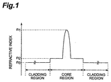
- Fig. 1 is a chart showing the refractive index profile of a dispersion-shifted fiber having a double core structure.
- the core region is constituted by an inner core having a refractive index n1 and an outer core having a refractive index n2 ( ⁇ n1), whereas a single cladding layer having a refractive index n3 ( ⁇ n2 ⁇ is provided on the outer periphery of the core region.
- Fig. 2 is a graph showing the relationship between the mode field diameter and the increase in loss caused by microbend at a wavelength of 1.55 ⁇ m (1550 nm) concerning this optical fiber having the refractive index profile of a double core structure.
- the mode field diameter refers to Petermann-I mode field diameter.
- r is the radial positional variable from the core center taken as the origin
- E is the electric field amplitude and is a function of the positional variable r.
- the microbend loss is defined by the amount of increase in loss when an optical fiber having a length of 250 m is wound at a tension of 100 g around a bobbin having a barrel diameter of 280 mm whose surface is wrapped with a JIS #1000 sandpaper sheet.
- R is the radius of curvature of microbending applied to the optical fiber
- k is the wave number
- n1 is the refractive index of the core region
- Lc is the correlation length of the microbending applied to the optical fiber.
- microbend loss increases as the mode field diameter MFD1 is greater.
- the conventional optical fibers are designed in view of macrobend loss, no consideration has been given to microbend loss.
- microbend loss increases upon cabling.
- an object of the present invention to provide an optical fiber having, at least, a structure which can effectively suppress the increase in microbend loss.
- the optical fiber according to the present invention comprises a core region extending along a predetermined axis and a cladding region provided on the outer periphery of the core region, these core and cladding regions being constituted by at least three layers of glass regions having respective refractive indices different from each other. Also, this optical fiber is substantially insured its single mode with respect to light at a wavelength in use, e.g., in a 1.55- ⁇ m wavelength band (1500 nm to 1600 nm), and has a fiber diameter of 140 ⁇ m or more but 200 ⁇ m or less.
- the fiber diameter is 140 ⁇ m or more, the rigidity of the optical fiber according to the present invention is high even when the mode field diameter is large, whereby the increase in microbend loss is suppressed.
- the fiber diameter is not greater than 200 ⁇ m, the probability of the optical fiber breaking due to bending stresses is practically unproblematic.
- the optical fiber according to the present invention when the 1.55- ⁇ m wavelength band is employed as the wavelength band in use for WDM transmissions, it is preferred in the optical fiber according to the present invention that the absolute value of chromatic dispersion at a wavelength of 1550 nm be 5 ps/nm/km or less. Also, it is preferred that the Petermann-I mode field diameter be 11 ⁇ m or more. It is because of the fact that, if the mode field diameter is 11 ⁇ m or more, then the optical energy density per unit cross-sectional becomes smaller even when WDM signals are transmitted, whereby the occurrence of nonlinear optical phenomena can effectively be suppressed.
- optical fiber according to the present invention can be employed as a single-mode optical fiber such as dispersion-shifted fiber, dispersion-flattened fiber, dispersion-compensating fiber, or the like.
- the optical fiber according to the present invention when employed as a dispersion-flattened fiber, it is preferable for the optical fiber to have, for at least one wave length with in the wavelength band in use, a dispersion slope of 0.02 ps/nm 2 /km or less and an effective area of 50 ⁇ m 2 or more. More preferably, in particular, the dispersion slope is 0.02 ps/nm 2 /km or less in terms of absolute value.
- the optical fiber according to the present invention when employed as a dispersion-compensating fiber, it is preferable for the optical fiber to have, for at least one wavelength within the wavelength band in use, a chromatic dispersion of -18 ps/nm/km or less and an effective area of 17 ⁇ m 2 or more.
- the optical fiber according to the present invention when employed as an optical fiber having an enlarged effective area, it is preferable for the optical fiber to have, for at least one wavelength within the wavelength band in use, an effective area of 110 ⁇ m 2 or more.
- the optical energy density per unit cross-sectional area can be kept low in this optical fiber as well, whereby the occurrence of nonlinear optical phenomena can be suppressed effectively.
- the fiber diameter is 140 ⁇ m or more but 200 ⁇ m or less.
- its fiber diameter is preferably 150 ⁇ m or more but 200 ⁇ m or less since its microbend characteristics are likely to deteriorate in particular.
- the optical fiber according to the present invention When the optical fiber according to the present invention is employed in an optical cable, it is preferable for the optical fiber to have, for at least one wavelength within the wavelength band in use, an effective area of 17 ⁇ m 2 or more and a chromatic dispersion value of -83 ps/nm/km or more, and have a fiber diameter of 140 ⁇ m or more but 200 ⁇ m or less.
- Such an optical fiber aimed at cabling can be employed as a single-mode optical fiber such as dispersion-shifted fiber, dispersion-flattened fiber, dispersion-compensating fiber, or the like as well.
- the optical fiber according to the present invention is preferably an optical fiber which has a fiber diameter of 140 ⁇ m or more but 200 ⁇ m or less, and also has, for at least one wavelength within the wavelength band in use, an effective area of 17 ⁇ m 2 or more and a chromatic dispersion value of -83 ps/nm/km or more; and, further, preferably is an optical fiber which has a fiber diameter of 140 ⁇ m or more but 200 ⁇ m or less, and also has, for at least one wavelength within the wavelength band in use, an effective area of 17 ⁇ m 2 or more and a chromatic dispersion value of -48 ps/nm/km or more. Also, depending on the kind of optical fiber employed, the fiber diameter thereof is preferably 150 ⁇ m or more but 200 ⁇ m or less.
- the optical fiber 100 comprises a core region 110 extending along a predetermined axis and having an outside diameter a, and a cladding region 120 provided on the outer periphery of the core region 110 and having an outside diameter b (coinciding with the fiber diameter), whereas the core and cladding regions are constituted by at least three layers of glass regions having respective refractive indices different from each other in embodiments which will be explained in the following.
- the absolute value of chromatic dispersion at a wavelength of 1.55 ⁇ m (1550 nm) is 5 ps/nm/km or less
- the Petermann-I mode field diameter is 11 ⁇ m or more
- the fiber diameter b is 140 ⁇ m or more but 200 ⁇ m or less.
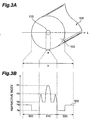
- optical fibers according to the first to third embodiments have a refractive index profile of double core structure identical to that shown in Fig. 1, whereas the optical fiber according to the fourth embodiment has a refractive index profile of a segmented core/depressed cladding structure as shown in Fig. 3B.
- each of the optical fibers according to the first to third embodiments is an optical fiber which is constituted by three glass layers (the inner core, outer core, and single cladding) and is insured its single mode in a wavelength band in use.
- the optical fiber according to the fourth embodiment is an optical fiber having a refractive index profile 500 of a segmented core/depressed cladding structure as shown in Fig. 3B, whereas the refractive index profile 500 also indicates the refractive index in each part on the line L in Fig. 3A.
- parts 510 and 520 indicate a core region having an outside diameter a and a cladding region having an outside diameter b, respectively.
- the core region is constituted by an inner core having a refractive index n1, an intermediate core provided on the outer periphery of the inner core and having a refractive index n2 ( ⁇ n1), and an outer core provided on the outer periphery of the intermediate core and having a refractive index n3 (>n2).
- the cladding region is constituted by an inner cladding provided on the outer periphery of the outer core and having a refractive index n4 ( ⁇ n3), and an outer cladding provided on the outer periphery of the inner cladding and having a refractive index n5 (> n4).
- the optical fiber according to the fourth embodiment is an optical fiber which is constituted by five layers of glass (the inner core, intermediate core, outer core, inner cladding, and outer cladding) and is insured its single mode in a wavelength band in use.
- optical fibers according to the first to fourth embodiments having the refractive index profiles mentioned above will now be explained successively.
- Fig. 4 is a table listing characteristics of each of the four kinds of samples 1a to 1d prepared as prototypes for explaining the optical fiber according to the first embodiment.
- the fiber diameter b is about 125 ⁇ m in sample 1a, about 140 ⁇ m in sample 1b, about 150 ⁇ m in sample 1c, and about 160 ⁇ m in sample 1d.
- each of the Petermann-I mode field diameter MFD1 (11.73 to 11.88 ⁇ m) given by the above-mentioned expressions (1a) and (1b), effective area (69.7 to 72.1 ⁇ m 2 ), chromatic dispersion value (-2.2 to -1.9 ps/nm/km), and cutoff wavelength (1.50 to 1.53 ⁇ m) is substantially the same among the four kinds of samples 1a to 1d.
- Such four kinds of samples 1a to 1d having respective values of fiber diameter b different from each other are obtained by preparing four kinds of preforms, which use core members having an identical diameter, whose outside diameter ratios between core member and cladding member differ from each other, and drawing them. Further, the periphery of each of the four kinds of samples 1a to 1d is provided with a coating layer, made of the same material, having an outside diameter of 250 ⁇ m.
- the values of the mode field diameter MFD1, effective area, and chromatic dispersion are those measured at a wavelength of 1.55 ⁇ m (1550 nm).
- FIG. 5 is a graph showing the respective results of evaluation of the four kinds of samples prepared as prototypes for explaining the optical fiber according to the first embodiment. It is seen from this graph that the amount of increase in loss, i.e., microbend loss, becomes smaller as the fiber diameter b is greater.
- the microbend loss increases upon cabling. For preventing this phenomenon from occurring, it is necessary that the microbend loss be suppressed to about 1 dB/km or less. Therefore, as can be seen from Fig. 5, it is necessary for the fiber diameter b to become 140 ⁇ m or more when the effective area is about 70 ⁇ m 2 .
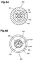
- Fig. 6A is a view showing the cross-sectional structure of an optical fiber unit
- Fig. 6B is a view showing the cross-sectional structure of an optical cable in which this optical fiber unit 200 is employed.
- optical fibers 100 each having a UV-curable resin 150 coated thereon as a coating layer are integrated with each other about a tension member 151 with a UV-curable resin 152. Further, the periphery of the UV-curable resin 152 is coated with a UV-curable resin 153, so that the optical fiber unit 200 is obtained.
- An optical cable 300 employing the optical fiber unit 200 is obtained by accommodating into a copper tube 253 the optical fiber unit 200 successively covered with a three-part pipe 250 made of a steel and tension piano wires 252 by way of a water-running prevention compound 251, and then successively covering the outer periphery of the copper tube 253 with a low-density polyethylene 254 and a high-density polyethylene 255.
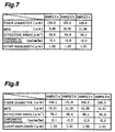
- Fig. 7 is a table listing characteristics of each of three kinds of samples 2a to 2c prepared as prototypes for explaining the optical fiber according to the second embodiment.
- sample 2a is a conventional optical fiber which has already been verified to be free from the problem caused by cabling.
- the fiber diameter b is about 125 ⁇ m in samples 2a and 2b, and about 140 ⁇ m in sample 2c.
- the Petermann-I mode field diameter MFD1 given by the above-mentioned expressions (1a) and (1b) is about 10 ⁇ m in sample 2a, and about 11 ⁇ m in samples 2b and 2c.
- the effective area is about 55 ⁇ m 2 in sample 2a, and about 65 ⁇ m 2 in samples 2b and 2c.
- each of the chromatic dispersion value (-2.2 to -2.0 ps/nm/km) and cutoff wavelength (1.51 to 1.53 ⁇ m) is substantially the same value among the three kinds of samples 2a to 2c.
- each of the three samples 2a to 2c is provided with a coating layer, made of the same material, having an outside diameter of 250 ⁇ m.
- the values of the mode field diameter MFD1, effective area, and chromatic dispersion are those measured at a wavelength of 1.55 ⁇ m.
- the optical fiber unit 200 having the cross-sectional structure shown in Figs. 6A and 6B was made.
- a hydraulic pressure of 100 atmospheres was applied to thus obtained optical fiber unit 200, so as to simulate the external pressure applied to the optical fiber unit 200 upon cabling.
- the amount of increase in loss, i.e., microbend loss, in sample 2b having a fiber diameter b of about 125 ⁇ m and an effective area of about 65 ⁇ m 2 was 20 mdB/km.
- the amount of increase in loss, i.e., microbend loss, in sample 2c having a fiber diameter b of about 140 ⁇ m and an effective area of about 65 ⁇ m 2 was not greater than 0.5 mdB/km, which was the limit of measurement, whereby this sample yielded a characteristic equivalent to that of the conventional sample 2a which had already been verified to be free from the problem caused by cabling.
- Fig. 8 is a table listing characteristics of each of four kinds of samples 3a to 3d prepared as prototypes for explaining the optical fiber according to the third embodiment.
- the fiber diameter b is about 150 ⁇ m in samples 3a and 3c, and about 170 ⁇ m in samples 3b and 3d.
- the Petermann-I mode field diameter MFD1 given by the above-mentioned expressions (1a) and (1b) is about 13.2 ⁇ m in samples 3a and 3b, and about 14.2 ⁇ m in samples 3c and 3d.
- the effective area is about 80 ⁇ m 2 in samples 3a and 3b, and about 90 ⁇ m 2 in samples 3c and 3d.
- each of the chromatic dispersion value (-2.0 to -2.2 ps/nm/km) and cutoff wavelength (1.50 to 1.53 ⁇ m) is substantially the same value among the four kinds of samples 3a to 3d.
- each of the four samples 3a to 3d is provided with a coating layer, made of the same material, having an outside diameter of 250 ⁇ m.
- the values of the mode field diameter MFD1, effective area, and chromatic dispersion are those measured at a wavelength of 1.55 ⁇ m.
- Fig. 9 is a graph showing respective results of evaluation of the four kinds of samples prepared as prototypes for explaining the optical fiber according to the third embodiment. As can be seen from this graph, when the effective area is about 80 ⁇ m 2 , the microbend loss can be suppressed to its target value of about 1 dB/km or less if the fiber diameter b is about 150 ⁇ m or more. On the other hand, when the effective area is about 90 ⁇ m 2 , the microbend loss can be suppressed to its target value of 1 dB/km or less if the fiber diameter b is about 170 ⁇ m or more.
- the microbend loss of an optical fiber is generated when an external force applied to the optical fiber causes random minute curvatures in the longitudinal direction in the core region of the optical fiber.
- This microbend loss is proportional to the square mean of the reciprocals of the radii of curvature of the minute curvatures.
- the external force applied to the optical fiber is constant, then the minute curvatures occurring in the optical fiber can be suppressed by increasing the rigidity of the optical fiber.
- D be the fiber diameter b of the optical fiber
- F 1-exp - L ⁇ Np ⁇ 1+ ⁇ s ⁇ p n ⁇ ts tp m /( n +1) -1
- L the optical fiber length to which a stress is applied in the state of its actual use
- Np the number of breaks per unit length at the time of screening test
- ⁇ s the stress upon its actual use
- ⁇ p the stress at the time of screening
- ts the time of actual use
- tp is the screening time
- n is the fatigue coefficient
- m is a parameter representing the gradient of a Weibull plot.
- Fig. 10 is a graph showing the relationship between the fiber diameter b and the probability of breaking according to above-mentioned expression (4) on the foregoing assumption. As can be seen from this graph, the probability of breaking becomes higher as the fiber diameter is greater. If the fiber diameter is 200 ⁇ m or less, however, then the probability of breaking is 10 -5 or lower, whereby there is no problem in practice.
- the refractive index n1 of the inner core, the refractive index n2 of the intermediate core, the refractive index n3 of the outer core, the refractive index n4 of the inner cladding, and the refractive index n5 of the outer cladding have relationships of n1 > n2, n3 > n2, and n5 > n4.
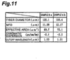
- Fig. 11 is a table listing characteristics of each of the two kinds of samples prepared as prototypes for explaining the optical fiber according to the fourth embodiment.
- the fiber diameter b is about 125 ⁇ m in sample 4a, and about 150 ⁇ m in sample 4b.
- each of the Petermann-I mode field diameter MFD1 (11.98 and 12.17 ⁇ m) given by the above-mentioned expressions (1a) and (1b), effective area (69.7 and 72.1 ⁇ m 2 ), chromatic dispersion value (-2.1 and -2.2 ps/nm/km), and cutoff wavelength (1.53 and 1.51 ⁇ m) is substantially the same value between the two kinds of samples 4a and 4b.
- the two kinds of samples 4a and 4b having respective values of fiber diameter b different from each other as such were obtained by preparing two kinds of preforms, which used core members having an identical diameter, whose outside diameter ratios between core member and cladding member differed from each, other, and drawing them. Further, the periphery of each of the two kinds of samples 4a and 4b is provided with a coating layer, made of the same material, having an outside diameter of 250 ⁇ m.
- the values of the mode field diameter MFD1, effective area, and chromatic dispersion are those measured at a wavelength of 1.55 ⁇ m.
- microbend loss was measured by a method similar to that in the case of the first embodiment.
- the microbend loss of sample 4a having a fiber diameter b of about 125 ⁇ was 4.12 dB/km
- the microbend loss of sample 4b having a fiber diameter b of about 150 ⁇ was 0.74 dB/km, whereby the latter was able to achieve the target value of microbend loss of about 1 dB/km or less, by which no increase in loss would be generated by cabling.
- Fig. 12 is a chart showing the refractive index profile in the fifth embodiment of the optical fiber according to the present invention.
- the optical fiber according to the fifth embodiment is a dispersion-flattened fiber, in which the core region 110 having an outside diameter a is constituted by an inner core having a refractive index n1 and an outside diameter of 3.75 ⁇ m, and an outside core provided on the outer periphery of the inner core and having a refractive index n2 (>n1) and an outside diameter of 8.25 ⁇ m.
- the refractive index profile 600 shown in Fig. 12 indicates the refractive index of each part on the line L in Fig. 3A, in which parts 610 and 620 show respective refractive indices in the core region 110 and cladding region 120.
- the relative refractive index difference ⁇ + of the outer core (refractive index n2) with respect to the outer cladding (refractive index n4) is +0.63%
- n core is the refractive index of the subject glass region
- n cld is the refractive index of the outer cladding taken as the reference.
- the refractive indices of the individual glass regions can be placed in any order, so that the relative refractive index difference of a region having a refractive index higher than that of the outer cladding becomes a positive value and is represented by ⁇ + , whereas the relative refractive index difference of a region having a refractive index lower than that of the outer cladding becomes a negative value and is represented by ⁇ - .
- the relative refractive index difference is expressed in terms of percentage.
- the samples prepared for evaluating the fifth embodiment consist of two kinds having fiber diameters of 125 ⁇ m and 160 ⁇ m, respectively. Also, the periphery of each of these samples is provided with a coating layer, made of the same material, having an outside diameter of 250 ⁇ m. Though their fiber diameters are different from each other, both of the samples have a chromatic dispersion value of 0.12 ps/nm/km at 1.55 ⁇ m, an effective area of 72 ⁇ m 2 at a wavelength of 1.55 ⁇ m, and a cutoff wavelength of 1.187 ⁇ m.
- dispersion slope is 0.0096 ps/nm 2 /km at a wavelength of 1530 nm, 0.0120 ps/nm 2 /km at a wavelength of 1550 nm, and 0.0265 ps/nm 2 /km at a wavelength of 1560 nm.
- dispersion slope refers to the gradient of the graph indicating the chromatic dispersion value in a predetermined wavelength band.
- the microbend loss at a wavelength of 1.55 ⁇ m (1550 nm) was evaluated in each sample and, as a result, was found to be 1.1 dB/km in the sample with a fiber diameter of 125 ⁇ m and 0.1 dB/km in the sample with a fiber diameter of 160 ⁇ m, whereby it was verified that the increase in loss caused by cabling was fully suppressed in the latter.
- Fig. 13 is a chart showing the refractive index profile in the sixth embodiment of the optical fiber according to the present invention.
- the optical fiber according to the sixth embodiment is a dispersion-compensating fiber in which the core region 110 having an outside diameter a is constituted by a single core having a refractive index n1 and an outside diameter a1.
- the cladding region 120 having an outside diameter b has a depressed cladding structure and is constituted by an inner cladding which is provided on the outer periphery of the core and which has a refractive index n2 ( ⁇ n1) and an outside diameter b1, and an outer cladding provided on the outer periphery of the inner cladding and having a refractive index n3 (> n2, ⁇ n1) and the outside diameter b.
- the refractive index profile 700 shown in Fig. 13 indicates the refractive index of each part on the line L in Fig. 3A, in which parts 710 and 720 show respective refractive indices in the core region 110 and cladding region 120.
- the relative refractive index difference ⁇ + of the core (refractive index n1) with respect to the outer cladding (refractive index n3) and the relative refractive index difference ⁇ - of the inner cladding (refractive index n2) with respect to the outer cladding (refractive index n3) are each given by the above-mentioned expression (5).
- the microbend loss at a wavelength of 1.55 ⁇ m (1550 nm) was evaluated in each sample and, as a result, was found to be 2.3 dB/km in the sample with a fiber diameter of 125 ⁇ m and 0.3 dB/km in the sample with a fiber diameter of 160 ⁇ m, whereby it was verified that the increase in loss caused by cabling was fully suppressed in the latter.
- optical fibers having a further enlarged effective area were evaluated. While the prepared samples have a refractive index profile identical to that of Fig. 13, their effective area is 122 ⁇ m 2 (110 ⁇ m 2 or more).
- the prepared samples consist of two kinds having fiber diameters of 125 ⁇ m and 160 ⁇ m, respectively. Also, the periphery of each of these samples is provided with a coating layer, made of the same material, having an outside diameter of 250 ⁇ m.
- the relative refractive index difference ⁇ + of the core (refractive index n1) with respect to the outer cladding (refractive index n3) is +0.28%
- the relative refractive index difference ⁇ - of the inner cladding (refractive index n2) with respect to the outer cladding (refractive index n3) is -0.14%
- the cutoff wavelength is 1.49 ⁇ m
- the effective area at a wavelength of 1.55 ⁇ m is 122 ⁇ m 2
- the chromatic dispersion value at a wavelength of 1.55 ⁇ m is 22.1 ps/nm/km
- the dispersion slope at a wavelength of 1.55 ⁇ m is 0.062 ps/nm 2 /km.
- the microbend loss at a wavelength of 1.55 ⁇ m (1550 nm) was evaluated in each sample and, as a result, was found to be 1.3 dB/km in the sample with a fiber diameter of 125 ⁇ m and 0.2 dB/km in the sample with a fiber diameter of 160 ⁇ m, whereby it was verified that the increase in loss caused by cabling was fully suppressed in the latter.
- the optical fiber according to the present invention has a fiber diameter of 140 ⁇ m or more but 200 ⁇ m or less, the increase in microbend loss is effectively Suppressed, and the probability of breaking caused by bending stresses can be lowered to such an extent that it is practically unproblematic. Also, if the absolute value of chromatic dispersion at a wavelength of 1.55 ⁇ m is 5 ps/nm/km or less, and the Petermann-I mode field diameter is 11 ⁇ m or more, then the occurrence of nonlinear optical phenomena is suppressed, whereby the optical fiber can suitably be used as an optical transmission line in WDM transmission systems utilizing the wavelength band of 1.55 ⁇ m.
- the present invention can be modified in various manners.
- the refractive index profile may have any structure without being limited to the double core structure and segmented core structure. It can also be realized by a ring core type refractive index profile in which a ring core region of a ring shape having a higher refractive index is provided around a center region having a lower refractive index.
- the optical fiber since the fiber diameter is 140 ⁇ m or more, the optical fiber has a high rigidity, so that the increase in microbend loss is suppressed, whereas the probability of the optical fiber breaking due to bending stresses is practically unproblematic since the fiber diameter is 200 ⁇ m or less. Also, if the absolute value of chromatic dispersion at a wavelength of 1.55 ⁇ m is 5 ps/nm/km or less, then the optical fiber is suitable for WDM transmissions in which this wavelength band is a wavelength in use.
- the optical fiber according to the present invention is suitable as an optical transmission line in WDM optical transmission systems.
Landscapes
- Physics & Mathematics (AREA)
- Chemical & Material Sciences (AREA)
- Dispersion Chemistry (AREA)
- General Physics & Mathematics (AREA)
- Optics & Photonics (AREA)
- Optical Communication System (AREA)
- Optical Fibers, Optical Fiber Cores, And Optical Fiber Bundles (AREA)
Abstract
The present invention relates to an optical fiber having, at least, a structure for effectively restraining microbend loss from increasing. This optical fiber is an optical fiber suitable for a dispersion-flattened fiber, a dispersion-compensating fiber, and the like, and insured its single mode in a wavelength band in use. In particular, since the fiber diameter is 140 mu m or more, this optical fiber has a high rigidity, so that the increase in microbend loss is effectively suppressed, whereas the probability of the optical fiber breaking due to bending stresses is practically unproblematic since the fiber diameter is 200 mu m or less. Also, since this optical fiber has a larger mode field diameter, it lowers the optical energy density per unit cross-sectional area, thereby effectively restraining nonlinear optical phenomena from occurring. <IMAGE>
Description
The present invention relates to an optical fiber which
is suitable as an optical transmission line in wavelength
division multiplexing (WDM) transmission systems.
WDM transmission lines which enable optical
transmissions, those of a large capacity and high speed in
particular, mainly utilize optical fibers. Recently,
however, the deterioration in light signals caused by
nonlinear optical phenomena such as four-wave mixing among
individual light signals occurring in an optical fiber has
become problematic in such WDM transmission systems.
Therefore, in the WDM transmission systems, it is important
that the occurrence of nonlinear optical phenomena be
suppressed, and to this aim, it is necessary that the mode
field diameter or effective area of the optical fiber be
increased, so as to lower the optical energy density per
unit cross-sectional area. For example, Japanese Patent
Application Laid-Open No. HEI 8-248251 discloses an optical
fiber having an effective area (70 µm2 or more) which is
greater than that of normal dispersion-shifted fibers.
It has been known that, in general, microbend
characteristics deteriorate as the mode field diameter or
the effective area increases, whereby the microbend loss
caused by cabling becomes greater.
For example, Fig. 1 is a chart showing the refractive
index profile of a dispersion-shifted fiber having a double
core structure. In this dispersion-shifted fiber, the core
region is constituted by an inner core having a refractive
index n1 and an outer core having a refractive index n2 (<
n1), whereas a single cladding layer having a refractive
index n3 (< n2〉 is provided on the outer periphery of the
core region. On the other hand, Fig. 2 is a graph showing
the relationship between the mode field diameter and the
increase in loss caused by microbend at a wavelength of 1.55
µm (1550 nm) concerning this optical fiber having the
refractive index profile of a double core structure. In this
specification, the mode field diameter refers to Petermann-I
mode field diameter. This Petermann-I mode field diameter
is given by the following expressions (1a) and (1b):
MFD 1 = 2·w 1
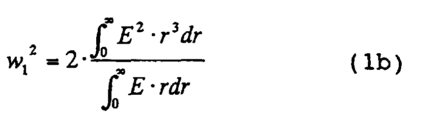 as shown in E.G. Neumann, "Single-Mode Fibers," pp. 225,
1988.
In expression (1b), r is the radial positional variable
from the core center taken as the origin, whereas E is the
electric field amplitude and is a function of the positional
variable r. The microbend loss is defined by the amount of
increase in loss when an optical fiber having a length of
250 m is wound at a tension of 100 g around a bobbin having
a barrel diameter of 280 mm whose surface is wrapped with
a JIS #1000 sandpaper sheet.
Also, from the results of theoretical studies, it has
been known that the relationships of the following
expressions (2a) to (2c) exist between microbend loss Δ
α and mode field diameter MFD1:
Δα = 14 ·(1 R 2 )·(k ·n 1·w 1 )2 ·Φ(Δβ) Δβ = 1 w 1 2 ·k·n 1 Φ(Δβ) = π½ ·Lc ·exp- Δβ·Lc 2 2
In these expressions, R is the radius of curvature of
microbending applied to the optical fiber, k is the wave
number, n1 is the refractive index of the core region, and
Lc is the correlation length of the microbending applied
to the optical fiber.
As can be seen from Fig. 2 and expressions (2a) to (2c)
mentioned above, the microbend loss increases as the mode
field diameter MFD1 is greater. However, though the
conventional optical fibers are designed in view of macrobend
loss, no consideration has been given to microbend loss.
Also, it has been known that, if the amount of increase in
loss measured when an optical fiber is wound around a bobbin
whose surface is wrapped with sandpaper, as an index for
cabling an optical fiber, exceeds about 1 dB/km, then
microbend loss increases upon cabling. Hence, it is clear
that microbend loss increases upon cabling in an optical
fiber such as the one mentioned above.
In order to overcome such problems, it is an object
of the present invention to provide an optical fiber having,
at least, a structure which can effectively suppress the
increase in microbend loss.
For achieving the above-mentioned object, the optical
fiber according to the present invention comprises a core
region extending along a predetermined axis and a cladding
region provided on the outer periphery of the core region,
these core and cladding regions being constituted by at least
three layers of glass regions having respective refractive
indices different from each other. Also, this optical fiber
is substantially insured its single mode with respect to
light at a wavelength in use, e.g., in a 1.55-µm wavelength
band (1500 nm to 1600 nm), and has a fiber diameter of 140
µm or more but 200 µm or less. Thus, since the fiber diameter
is 140 µm or more, the rigidity of the optical fiber according
to the present invention is high even when the mode field
diameter is large, whereby the increase in microbend loss
is suppressed. On the other hand, since the fiber diameter
is not greater than 200 µm, the probability of the optical
fiber breaking due to bending stresses is practically
unproblematic.
In particular, when the 1.55-µm wavelength band is
employed as the wavelength band in use for WDM transmissions,
it is preferred in the optical fiber according to the present
invention that the absolute value of chromatic dispersion
at a wavelength of 1550 nm be 5 ps/nm/km or less. Also, it
is preferred that the Petermann-I mode field diameter be
11 µm or more. It is because of the fact that, if the mode
field diameter is 11 µm or more, then the optical energy
density per unit cross-sectional becomes smaller even when
WDM signals are transmitted, whereby the occurrence of
nonlinear optical phenomena can effectively be suppressed.
The optical fiber according to the present invention
can be employed as a single-mode optical fiber such as
dispersion-shifted fiber, dispersion-flattened fiber,
dispersion-compensating fiber, or the like.
In particular, when the optical fiber according to the
present invention is employed as a dispersion-flattened fiber,
it is preferable for the optical fiber to have, for at least
one wave length with in the wavelength band in use, a dispersion
slope of 0.02 ps/nm2/km or less and an effective area of 50
µm2 or more. More preferably, in particular, the dispersion
slope is 0.02 ps/nm2/km or less in terms of absolute value.
Also, when the optical fiber according to the present
invention is employed as a dispersion-compensating fiber,
it is preferable for the optical fiber to have, for at least
one wavelength within the wavelength band in use, a chromatic
dispersion of -18 ps/nm/km or less and an effective area
of 17 µm2 or more.
Further, when the optical fiber according to the present
invention is employed as an optical fiber having an enlarged
effective area, it is preferable for the optical fiber to
have, for at least one wavelength within the wavelength band
in use, an effective area of 110 µm2 or more. The optical
energy density per unit cross-sectional area can be kept
low in this optical fiber as well, whereby the occurrence
of nonlinear optical phenomena can be suppressed effectively.
In various kinds of optical fibers mentioned above,
the fiber diameter is 140 µm or more but 200 µm or less.
In the case of a dispersion-compensating fiber having such
characteristics as those mentioned above, however, its fiber
diameter is preferably 150 µm or more but 200 µm or less
since its microbend characteristics are likely to deteriorate
in particular.
When the optical fiber according to the present
invention is employed in an optical cable, it is preferable
for the optical fiber to have, for at least one wavelength
within the wavelength band in use, an effective area of 17
µm2 or more and a chromatic dispersion value of -83 ps/nm/km
or more, and have a fiber diameter of 140 µm or more but
200 µm or less. Such an optical fiber aimed at cabling can
be employed as a single-mode optical fiber such as
dispersion-shifted fiber, dispersion-flattened fiber,
dispersion-compensating fiber, or the like as well.
As explained in the foregoing, In view of various
circumstances applicable thereto, the optical fiber
according to the present invention is preferably an optical
fiber which has a fiber diameter of 140 µm or more but 200
µm or less, and also has, for at least one wavelength within
the wavelength band in use, an effective area of 17 µm2 or
more and a chromatic dispersion value of -83 ps/nm/km or
more; and, further, preferably is an optical fiber which
has a fiber diameter of 140 µm or more but 200 µm or less,
and also has, for at least one wavelength within the wavelength
band in use, an effective area of 17 µm2 or more and a chromatic
dispersion value of -48 ps/nm/km or more. Also, depending
on the kind of optical fiber employed, the fiber diameter
thereof is preferably 150 µm or more but 200 µm or less.
Individual embodiments of the optical fiber according
to the present invention will now be explained in detail
with reference to Figs. 1, 3A, 3B, 4, 5, 6A, 6B, and 7 to
14.
Here, as shown in Fig. 3A, the optical fiber 100
according to the present invention comprises a core region
110 extending along a predetermined axis and having an outside
diameter a, and a cladding region 120 provided on the outer
periphery of the core region 110 and having an outside diameter
b (coinciding with the fiber diameter), whereas the core
and cladding regions are constituted by at least three layers
of glass regions having respective refractive indices
different from each other in embodiments which will be
explained in the following. Also, in each of the optical
fibers according to the respective embodiments, the absolute
value of chromatic dispersion at a wavelength of 1.55 µm
(1550 nm) is 5 ps/nm/km or less, the Petermann-I mode field
diameter is 11 µm or more, and the fiber diameter b is 140
µm or more but 200 µm or less.
The optical fibers according to the first to third
embodiments have a refractive index profile of double core
structure identical to that shown in Fig. 1, whereas the
optical fiber according to the fourth embodiment has a
refractive index profile of a segmented core/depressed
cladding structure as shown in Fig. 3B.
The refractive index profile shown in Fig. 1 indicates
the refractive index in each part on the line L in Fig. 3A.
In the optical fibers of the first to third embodiments,
the core region 110 having the outside diameter a is
constituted by an inner core having a refractive index n1,
and an outside core provided on the outer periphery of the
inner core and having a refractive index n2 (< n1), whereas
the cladding region 120 having the outside diameter b
(coinciding with the fiber diameter) is constituted by a
single cladding provided on the outer periphery of the outer
core and having a refractive index n3 (< n2). Thus, each
of the optical fibers according to the first to third
embodiments is an optical fiber which is constituted by three
glass layers (the inner core, outer core, and single cladding)
and is insured its single mode in a wavelength band in use.
On the other hand, the optical fiber according to the
fourth embodiment is an optical fiber having a refractive
index profile 500 of a segmented core/depressed cladding
structure as shown in Fig. 3B, whereas the refractive index
profile 500 also indicates the refractive index in each part
on the line L in Fig. 3A. In particular, in the refractive
index profile 500, parts 510 and 520 indicate a core region
having an outside diameter a and a cladding region having
an outside diameter b, respectively. In the fourth
embodiment, the core region is constituted by an inner core
having a refractive index n1, an intermediate core provided
on the outer periphery of the inner core and having a refractive
index n2 (< n1), and an outer core provided on the outer
periphery of the intermediate core and having a refractive
index n3 (>n2). On the other hand, the cladding region is
constituted by an inner cladding provided on the outer
periphery of the outer core and having a refractive index
n4 (<n3), and an outer cladding provided on the outer periphery
of the inner cladding and having a refractive index n5 (>
n4). Thus, the optical fiber according to the fourth
embodiment is an optical fiber which is constituted by five
layers of glass (the inner core, intermediate core, outer
core, inner cladding, and outer cladding) and is insured
its single mode in a wavelength band in use.
The optical fibers according to the first to fourth
embodiments having the refractive index profiles mentioned
above will now be explained successively.
First, for explaining the optical fiber according to
the first embodiment, four kinds of optical fibers (sample
1a to sample 1d) having substantially the same Petermann-I
mode field diameter MFD1 and respective values of fiber
diameter b different from each other were prepared as
prototypes and evaluated. Fig. 4 is a table listing
characteristics of each of the four kinds of samples 1a to
1d prepared as prototypes for explaining the optical fiber
according to the first embodiment.
The fiber diameter b is about 125 µm in sample 1a,
about 140 µm in sample 1b, about 150 µm in sample 1c, and
about 160 µm in sample 1d. Here, each of the Petermann-I
mode field diameter MFD1 (11.73 to 11.88 µm) given by the
above-mentioned expressions (1a) and (1b), effective area
(69.7 to 72.1 µm2), chromatic dispersion value (-2.2 to -1.9
ps/nm/km), and cutoff wavelength (1.50 to 1.53 µm) is
substantially the same among the four kinds of samples 1a
to 1d.
Such four kinds of samples 1a to 1d having respective
values of fiber diameter b different from each other are
obtained by preparing four kinds of preforms, which use core
members having an identical diameter, whose outside diameter
ratios between core member and cladding member differ from
each other, and drawing them. Further, the periphery of each
of the four kinds of samples 1a to 1d is provided with a
coating layer, made of the same material, having an outside
diameter of 250 µm. The values of the mode field diameter
MFD1, effective area, and chromatic dispersion are those
measured at a wavelength of 1.55 µm (1550 nm).
For each of these four kinds of samples 1a to 1d,
microbend loss was measured. In this measurement, each
optical fiber having a length of 250 m was wound at a tension
of 100 g around a bobbin having a barrel diameter of 280
mm whose surface was wrapped with a JIS #1000 sandpaper sheet,
and the resulting amount of increase in loss was defined
as the microbend loss. Fig. 5 is a graph showing the
respective results of evaluation of the four kinds of samples
prepared as prototypes for explaining the optical fiber
according to the first embodiment. It is seen from this graph
that the amount of increase in loss, i.e., microbend loss,
becomes smaller as the fiber diameter b is greater.
When an optical cable having a cross-sectional
structure such as those shown in Figs. 6A and 6B is being
made, the microbend loss increases upon cabling. For
preventing this phenomenon from occurring, it is necessary
that the microbend loss be suppressed to about 1 dB/km or
less. Therefore, as can be seen from Fig. 5, it is necessary
for the fiber diameter b to become 140 µm or more when the
effective area is about 70 µm2.
Here, Fig. 6A is a view showing the cross-sectional
structure of an optical fiber unit, whereas Fig. 6B is a
view showing the cross-sectional structure of an optical
cable in which this optical fiber unit 200 is employed. In
Fig. 6A, optical fibers 100 each having a UV-curable resin
150 coated thereon as a coating layer are integrated with
each other about a tension member 151 with a UV-curable resin
152. Further, the periphery of the UV-curable resin 152 is
coated with a UV-curable resin 153, so that the optical fiber
unit 200 is obtained. An optical cable 300 employing the
optical fiber unit 200 is obtained by accommodating into
a copper tube 253 the optical fiber unit 200 successively
covered with a three-part pipe 250 made of a steel and tension
piano wires 252 by way of a water-running prevention compound
251, and then successively covering the outer periphery of
the copper tube 253 with a low-density polyethylene 254 and
a high-density polyethylene 255.
Next, in the second embodiment, the comparison between
characteristics of a conventional optical fiber which has
already been verified to be free from the problem caused
by cabling and characteristics of the optical fiber according
to the second embodiment will be explained. Fig. 7 is a table
listing characteristics of each of three kinds of samples
2a to 2c prepared as prototypes for explaining the optical
fiber according to the second embodiment. Among them, sample
2a is a conventional optical fiber which has already been
verified to be free from the problem caused by cabling.
The fiber diameter b is about 125 µm in samples 2a
and 2b, and about 140 µm in sample 2c. The Petermann-I mode
field diameter MFD1 given by the above-mentioned expressions
(1a) and (1b) is about 10 µm in sample 2a, and about 11 µm
in samples 2b and 2c. The effective area is about 55 µm2
in sample 2a, and about 65 µm2 in samples 2b and 2c. Here,
each of the chromatic dispersion value (-2.2 to -2.0 ps/nm/km)
and cutoff wavelength (1.51 to 1.53 µm) is substantially
the same value among the three kinds of samples 2a to 2c.
The periphery of each of the three samples 2a to 2c is provided
with a coating layer, made of the same material, having an
outside diameter of 250 µm. The values of the mode field
diameter MFD1, effective area, and chromatic dispersion are
those measured at a wavelength of 1.55 µm.
Using these three kinds of samples 2a to 2c, the optical
fiber unit 200 having the cross-sectional structure shown
in Figs. 6A and 6B was made. A hydraulic pressure of 100
atmospheres was applied to thus obtained optical fiber unit
200, so as to simulate the external pressure applied to the
optical fiber unit 200 upon cabling. As a result, the amount
of increase in loss, i.e., microbend loss, in sample 2b having
a fiber diameter b of about 125 µm and an effective area
of about 65 µm2 was 20 mdB/km. On the other hand, the amount
of increase in loss, i.e., microbend loss, in sample 2c having
a fiber diameter b of about 140 µm and an effective area
of about 65 µm2 was not greater than 0.5 mdB/km, which was
the limit of measurement, whereby this sample yielded a
characteristic equivalent to that of the conventional sample
2a which had already been verified to be free from the problem
caused by cabling.
The third embodiment will now be explained. In the
third embodiment, for optical fibers having a further greater
effective area, the effect of reducing microbend loss
resulting from the increase in fiber diameter was verified.
Fig. 8 is a table listing characteristics of each of four
kinds of samples 3a to 3d prepared as prototypes for explaining
the optical fiber according to the third embodiment.
The fiber diameter b is about 150 µm in samples 3a
and 3c, and about 170 µm in samples 3b and 3d. The Petermann-I
mode field diameter MFD1 given by the above-mentioned
expressions (1a) and (1b) is about 13.2 µm in samples 3a
and 3b, and about 14.2 µm in samples 3c and 3d. The effective
area is about 80 µm2 in samples 3a and 3b, and about 90 µm2
in samples 3c and 3d. On the other hand, each of the chromatic
dispersion value (-2.0 to -2.2 ps/nm/km) and cutoff
wavelength (1.50 to 1.53 µm) is substantially the same value
among the four kinds of samples 3a to 3d. The periphery of
each of the four samples 3a to 3d is provided with a coating
layer, made of the same material, having an outside diameter
of 250 µm. The values of the mode field diameter MFD1,
effective area, and chromatic dispersion are those measured
at a wavelength of 1.55 µm.
For each of these four kinds of samples 3a to 3d,
microbend loss was measured. The method of measuring the
microbend loss was similar to that in the case of the first
embodiment. Fig. 9 is a graph showing respective results
of evaluation of the four kinds of samples prepared as
prototypes for explaining the optical fiber according to
the third embodiment. As can be seen from this graph, when
the effective area is about 80 µm2, the microbend loss can
be suppressed to its target value of about 1 dB/km or less
if the fiber diameter b is about 150 µm or more. On the
other hand, when the effective area is about 90 µm2, the
microbend loss can be suppressed to its target value of 1
dB/km or less if the fiber diameter b is about 170 µm or
more.
From the foregoing, it is seen that, even when the
effective area is large, the microbend loss can be suppressed
to its target value of about 1 dB/km or less if the fiber
diameter is large. This fact can be explained by the
following as well. Namely, the microbend loss of an optical
fiber is generated when an external force applied to the
optical fiber causes random minute curvatures in the
longitudinal direction in the core region of the optical
fiber. This microbend loss is proportional to the square
mean of the reciprocals of the radii of curvature of the
minute curvatures. On the other hand, if the external force
applied to the optical fiber is constant, then the minute
curvatures occurring in the optical fiber can be suppressed
by increasing the rigidity of the optical fiber. Letting
D be the fiber diameter b of the optical fiber, the rigidity
(bending moment) I of the optical fiber is given by the
following expression (3):
I = π·D 4 /64
Therefore, increasing the fiber diameter D of the
optical fiber greatly improves the rigidity I of the optical
fiber, thereby suppressing minute curvatures and greatly
reducing the microbend loss.
For example, when an optical fiber having a fiber
diameter of 200.3 µm, an effective area of 90.4 µm2, a
chromatic dispersion value of -2.1 ps/nm/km, a cutoff
wavelength of 1.73 µm, and a coating layer outside diameter
of 250 µm was prepared as a prototype, and its microbend
loss was measured in a manner similar to that of the first
embodiment, the resulting value was 0.3 dB/km. This
characteristic is on a par with that of the conventional
optical fiber which has already been verified to be free
from the problem caused by cabling.
As the fiber diameter b increases, however, the stress
in the fiber surface (the surface of the outermost cladding
layer) occurring when the optical fiber is bent becomes
greater than that in the conventional optical fiber, thereby
increasing the probability of breaking upon bending. Hence,
the range of fiber diameter b within which the probability
of breaking is practically unproblematic will now be
calculated by way of trial. The probability of breaking F
of the optical fiber after passing a screening test is given
by the following expression (4):
F = 1-exp-L ·Np · 1+ σ s σ p n · ts tp m /(n +1) -1
where L is the optical fiber length to which a stress is
applied in the state of its actual use, Np is the number
of breaks per unit length at the time of screening test,
σs is the stress upon its actual use, σp is the stress at
the time of screening, ts is the time of actual use, tp is
the screening time, n is the fatigue coefficient, and m is
a parameter representing the gradient of a Weibull plot.
It is assumed that smaller-diameter bending in an
optical fiber at the time of actual use occurs in a surplus
length portion which is left for fusion connection in a
repeater, and that one turn of bending with a diameter of
30 mm exists in one repeater at worst. Also, it is assumed
that the total optical fiber length of the optical
transmission system is 9000 km, in which repeaters are
disposed at intervals of 50 km on average. Then, the fiber
length L to which the bending with a diameter of 30 mm is
applied becomes 16.9 m in the optical transmission system
as a whole. It is also assumed that the number of breaks
per unit length at the time of screening test Np is 2 × 10⁻⁵,
and the stress σp at the time of screening is 2.2%. Let
the time of actual use ts be 25 years, and the screening
time tp be 1 second. Let the fatigue coefficient n be 20,
and the parameter m representing the gradient of the Weibull
plot be 10.
Fig. 10 is a graph showing the relationship between
the fiber diameter b and the probability of breaking according
to above-mentioned expression (4) on the foregoing assumption.
As can be seen from this graph, the probability of breaking
becomes higher as the fiber diameter is greater. If the fiber
diameter is 200 µm or less, however, then the probability
of breaking is 10-5 or lower, whereby there is no problem
in practice.
The fourth embodiment will now be explained. Prepared
for the evaluation of the fourth embodiment were two kinds
of samples 4a and 4b, each having a refractive index profile
of a dispersion-shifted optical fiber with the segmented
core/depressed cladding structure shown in Fig. 3B, whose
values of Petermann-I mode field diameter MFD1 were
substantially identical to each other, whereas their values
of fiber diameter b were different from each other.
Here, as mentioned above, the refractive index n1 of
the inner core, the refractive index n2 of the intermediate
core, the refractive index n3 of the outer core, the refractive
index n4 of the inner cladding, and the refractive index
n5 of the outer cladding have relationships of n1 > n2, n3
> n2, and n5 > n4.
Fig. 11 is a table listing characteristics of each of
the two kinds of samples prepared as prototypes for explaining
the optical fiber according to the fourth embodiment. The
fiber diameter b is about 125 µm in sample 4a, and about
150 µm in sample 4b. On the other hand, each of the
Petermann-I mode field diameter MFD1 (11.98 and 12.17 µm)
given by the above-mentioned expressions (1a) and (1b),
effective area (69.7 and 72.1 µm2), chromatic dispersion
value (-2.1 and -2.2 ps/nm/km), and cutoff wavelength (1.53
and 1.51 µm) is substantially the same value between the
two kinds of samples 4a and 4b.
The two kinds of samples 4a and 4b having respective
values of fiber diameter b different from each other as such
were obtained by preparing two kinds of preforms, which used
core members having an identical diameter, whose outside
diameter ratios between core member and cladding member
differed from each, other, and drawing them. Further, the
periphery of each of the two kinds of samples 4a and 4b is
provided with a coating layer, made of the same material,
having an outside diameter of 250 µm. The values of the
mode field diameter MFD1, effective area, and chromatic
dispersion are those measured at a wavelength of 1.55 µm.
For each of these two kinds of samples 4a and 4b,
microbend loss was measured by a method similar to that in
the case of the first embodiment. As a result, while the
microbend loss of sample 4a having a fiber diameter b of
about 125 µ was 4.12 dB/km, the microbend loss of sample
4b having a fiber diameter b of about 150 µ was 0.74 dB/km,
whereby the latter was able to achieve the target value of
microbend loss of about 1 dB/km or less, by which no increase
in loss would be generated by cabling.
Fig. 12 is a chart showing the refractive index profile
in the fifth embodiment of the optical fiber according to
the present invention. The optical fiber according to the
fifth embodiment is a dispersion-flattened fiber, in which
the core region 110 having an outside diameter a is constituted
by an inner core having a refractive index n1 and an outside
diameter of 3.75 µm, and an outside core provided on the
outer periphery of the inner core and having a refractive
index n2 (>n1) and an outside diameter of 8.25 µm. On the
other hand, the cladding region 120 having an outside diameter
b has a depressed cladding structure and is constituted by
an inner cladding which is provided on the outer periphery
of the outer core and which has a refractive index n3 (=
n1) and an outside diameter of 15.0 µm, and an outside cladding
provided on the outer periphery of the inner cladding and
having a refractive index n4 (> n3, < n2) and an outside
diameter b.
The refractive index profile 600 shown in Fig. 12
indicates the refractive index of each part on the line L
in Fig. 3A, in which parts 610 and 620 show respective
refractive indices in the core region 110 and cladding region
120. Further, in the fifth embodiment, the relative
refractive index difference Δ+ of the outer core (refractive
index n2) with respect to the outer cladding (refractive
index n4) is +0.63%, whereas the relative refractive index
difference Δ- of each of the inner core (refractive index
n1) and the inner cladding (refractive index n3) with respect
to the outer cladding (refractive index n4) is -0.60%, each
given by the following expression (5):
Δ = (ncore 2 -ncld 2 )/ncld 2
In the above-mentioned expression (5), ncore is the
refractive index of the subject glass region, ncld is the
refractive index of the outer cladding taken as the reference.
In expression (5), the refractive indices of the individual
glass regions can be placed in any order, so that the relative
refractive index difference of a region having a refractive
index higher than that of the outer cladding becomes a positive
value and is represented by Δ+, whereas the relative
refractive index difference of a region having a refractive
index lower than that of the outer cladding becomes a negative
value and is represented by Δ-. In this specification, the
relative refractive index difference is expressed in terms
of percentage.
The samples prepared for evaluating the fifth
embodiment consist of two kinds having fiber diameters of
125 µm and 160 µm, respectively. Also, the periphery of
each of these samples is provided with a coating layer, made
of the same material, having an outside diameter of 250 µm.
Though their fiber diameters are different from each other,
both of the samples have a chromatic dispersion value of
0.12 ps/nm/km at 1.55 µm, an effective area of 72 µm2 at
a wavelength of 1.55 µm, and a cutoff wavelength of 1.187
µm. Also, their dispersion slope is 0.0096 ps/nm2/km at
a wavelength of 1530 nm, 0.0120 ps/nm2/km at a wavelength
of 1550 nm, and 0.0265 ps/nm2/km at a wavelength of 1560 nm.
Here, the dispersion slope refers to the gradient of the
graph indicating the chromatic dispersion value in a
predetermined wavelength band.
The microbend loss at a wavelength of 1.55 µm (1550
nm) was evaluated in each sample and, as a result, was found
to be 1.1 dB/km in the sample with a fiber diameter of 125
µm and 0.1 dB/km in the sample with a fiber diameter of 160
µm, whereby it was verified that the increase in loss caused
by cabling was fully suppressed in the latter.
Fig. 13 is a chart showing the refractive index profile
in the sixth embodiment of the optical fiber according to
the present invention. The optical fiber according to the
sixth embodiment is a dispersion-compensating fiber in which
the core region 110 having an outside diameter a is constituted
by a single core having a refractive index n1 and an outside
diameter a1. On the other hand, the cladding region 120
having an outside diameter b has a depressed cladding
structure and is constituted by an inner cladding which is
provided on the outer periphery of the core and which has
a refractive index n2 (< n1) and an outside diameter b1,
and an outer cladding provided on the outer periphery of
the inner cladding and having a refractive index n3 (> n2,
< n1) and the outside diameter b.
The refractive index profile 700 shown in Fig. 13
indicates the refractive index of each part on the line L
in Fig. 3A, in which parts 710 and 720 show respective
refractive indices in the core region 110 and cladding region
120. Further, in the sixth embodiment, the relative
refractive index difference Δ+ of the core (refractive index
n1) with respect to the outer cladding (refractive index
n3) and the relative refractive index difference Δ- of the
inner cladding (refractive index n2) with respect to the
outer cladding (refractive index n3) are each given by the
above-mentioned expression (5).
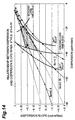
The samples prepared for evaluating the sixth
embodiment are those, among samples with Δ+ = +0.9% and Δ-=
-0.44% as shown in Fig. 14, having characteristics
indicated by point P in Fig. 14 in which the chromatic
dispersion value at 1.55 µm (1550 nm) is -33 ps/nm/km, the
dispersion slope is -0.10 ps/nm2/km, and the ratio Ra (= a1/b1)
of the outside diameter a1 of the core region 110 to the
outside diameter b1 of the inner cladding is 0.6. They
consist of two kinds having fiber diameters of 125 µm and
160 µm, respectively. Also, the periphery of each of these
samples is provided with a coating layer, made of the same
material, having an outside diameter of 250 µm.
The microbend loss at a wavelength of 1.55 µm (1550
nm) was evaluated in each sample and, as a result, was found
to be 2.3 dB/km in the sample with a fiber diameter of 125
µm and 0.3 dB/km in the sample with a fiber diameter of 160
µm, whereby it was verified that the increase in loss caused
by cabling was fully suppressed in the latter.
Further, in the seventh embodiment, optical fibers
having a further enlarged effective area were evaluated.
While the prepared samples have a refractive index profile
identical to that of Fig. 13, their effective area is 122
µm2 (110 µm2 or more). The prepared samples consist of two
kinds having fiber diameters of 125 µm and 160 µm,
respectively. Also, the periphery of each of these samples
is provided with a coating layer, made of the same material,
having an outside diameter of 250 µm. In both of the samples,
though their fiber diameters are different from each other,
the relative refractive index difference Δ+ of the core
(refractive index n1) with respect to the outer cladding
(refractive index n3) is +0.28%, the relative refractive
index difference Δ- of the inner cladding (refractive index
n2) with respect to the outer cladding (refractive index
n3) is -0.14%, the cutoff wavelength is 1.49 µm, the effective
area at a wavelength of 1.55 µm is 122 µm2, the chromatic
dispersion value at a wavelength of 1.55 µm is 22.1 ps/nm/km,
and the dispersion slope at a wavelength of 1.55 µm is 0.062
ps/nm2/km.
The microbend loss at a wavelength of 1.55 µm (1550
nm) was evaluated in each sample and, as a result, was found
to be 1.3 dB/km in the sample with a fiber diameter of 125
µm and 0.2 dB/km in the sample with a fiber diameter of 160
µm, whereby it was verified that the increase in loss caused
by cabling was fully suppressed in the latter.
As explained in the foregoing, since the optical fiber
according to the present invention has a fiber diameter of
140 µm or more but 200 µm or less, the increase in microbend
loss is effectively Suppressed, and the probability of
breaking caused by bending stresses can be lowered to such
an extent that it is practically unproblematic. Also, if
the absolute value of chromatic dispersion at a wavelength
of 1.55 µm is 5 ps/nm/km or less, and the Petermann-I mode
field diameter is 11 µm or more, then the occurrence of
nonlinear optical phenomena is suppressed, whereby the
optical fiber can suitably be used as an optical transmission
line in WDM transmission systems utilizing the wavelength
band of 1.55 µm.
Without being restricted to the above-mentioned
individual embodiments, the present invention can be modified
in various manners. For example, the refractive index
profile may have any structure without being limited to the
double core structure and segmented core structure. It can
also be realized by a ring core type refractive index profile
in which a ring core region of a ring shape having a higher
refractive index is provided around a center region having
a lower refractive index.
In the present invention, as explained in the foregoing,
since the fiber diameter is 140 µm or more, the optical fiber
has a high rigidity, so that the increase in microbend loss
is suppressed, whereas the probability of the optical fiber
breaking due to bending stresses is practically unproblematic
since the fiber diameter is 200 µm or less. Also, if the
absolute value of chromatic dispersion at a wavelength of
1.55 µm is 5 ps/nm/km or less, then the optical fiber is
suitable for WDM transmissions in which this wavelength band
is a wavelength in use. Further, in accordance with the
present invention, since the mode field diameter is 11 µm
or more, the optical energy density per unit cross-sectional
area is so low that the occurrence of nonlinear optical
phenomena can be suppressed effectively. Therefore, the
optical fiber according to the present invention is suitable
as an optical transmission line in WDM optical transmission
systems.
Claims (6)
- An optical fiber comprising a core region extending along a predetermined axis and a cladding region provided on the outer periphery of said core region, said core and cladding regions being constituted by at least three layers of glass regions having respective refractive indices different from each other;
said optical fiber substantially insured its single mode with respect to light at a wavelength in use and having a fiber diameter of 140 µm or more but 200 µm or less. - An optical fiber having, for at least one wavelength in a wavelength band in use, a dispersion slope of 0.02 ps/nm2/km or less and an effective area of 50 µm2 or more;
said optical fiber having a fiber diameter of 140 µm or more but 200 µm or less. - An optical fiber having, for at least one wavelength in a wavelength band in use, a chromatic dispersion of -18 ps/nm/km or less and an effective area of 17 µm2 or more;
said optical fiber having a fiber diameter of 140 µm or more but 200 µm or less. - An optical fiber having, for at least one wavelength in a wavelength band in use, an effective area of 110 µm2 or more;
said optical fiber having a fiber diameter of 140 µm or more but 200 µm or less. - An optical fiber according to one of claims 1 to 4, wherein said optical fiber has, at a wavelength of 1550 nm, a chromatic dispersion of 5 ps/nm/km or less in terms of absolute value and a Petermann-I mode field diameter of 11 µm or more.
- An optical fiber comprising a core region extending along a predetermined axis and a cladding region provided on the outer periphery of said core region, said core and cladding regions being constituted by at least three layers of glass regions having respective refractive indices different from each other, said optical fiber substantially insured its single mode with respect to light in a wavelength band in use;
said optical fiber having, for at least one wavelength in said wavelength band in use, an effective area of 17 µm2 or more, a chromatic dispersion value of -83 ps/nm/km or more, and a fiber diameter of 140 µm or more but 200 µm or less.
Applications Claiming Priority (3)
| Application Number | Priority Date | Filing Date | Title |
|---|---|---|---|
| JP19171998 | 1998-07-07 | ||
| JP19171998 | 1998-07-07 | ||
| PCT/JP1999/003672 WO2000002074A1 (en) | 1998-07-07 | 1999-07-07 | Optical fiber |
Publications (2)
| Publication Number | Publication Date |
|---|---|
| EP1096279A1 true EP1096279A1 (en) | 2001-05-02 |
| EP1096279A4 EP1096279A4 (en) | 2006-11-02 |
Family
ID=16279350
Family Applications (1)
| Application Number | Title | Priority Date | Filing Date |
|---|---|---|---|
| EP99929737A Withdrawn EP1096279A4 (en) | 1998-07-07 | 1999-07-07 | OPTICAL FIBER |
Country Status (9)
| Country | Link |
|---|---|
| US (2) | US6345140B1 (en) |
| EP (1) | EP1096279A4 (en) |
| JP (1) | JP4763106B2 (en) |
| KR (1) | KR20010053394A (en) |
| CN (2) | CN1134682C (en) |
| AU (1) | AU760721B2 (en) |
| CA (1) | CA2336941A1 (en) |
| TW (1) | TW436645B (en) |
| WO (1) | WO2000002074A1 (en) |
Cited By (2)
| Publication number | Priority date | Publication date | Assignee | Title |
|---|---|---|---|---|
| EP1030200B1 (en) * | 1999-02-18 | 2008-11-19 | Draka Comteq B.V. | Optical fibre with large effective area and strong chromatic dispersion |
| WO2019173680A1 (en) * | 2018-03-08 | 2019-09-12 | Corning Incorporated | Quasi-single-mode optical fiber |
Families Citing this family (16)
| Publication number | Priority date | Publication date | Assignee | Title |
|---|---|---|---|---|
| US6711331B2 (en) * | 1998-07-07 | 2004-03-23 | Sumitomo Electric Industries, Ltd. | Optical fiber |
| US6477306B2 (en) * | 2000-04-11 | 2002-11-05 | Sumitomo Electric Industries, Ltd. | Dispersion-compensating optical fiber, and, optical transmission line and dispersion-compensating module respectively including the same |
| GB0101338D0 (en) * | 2001-01-18 | 2001-03-07 | Nds Ltd | Set-top-box with qam demodulator sharing between dtv/pvr and cable modem applications |
| US6490398B2 (en) * | 2001-02-21 | 2002-12-03 | Fitel Usa Corp. | Dispersion-compensating fiber having a high figure of merit |
| FR2828939B1 (en) * | 2001-08-27 | 2004-01-16 | Cit Alcatel | OPTICAL FIBER FOR A WAVELENGTH MULTIPLEXED TRANSMISSION SYSTEM |
| US6810185B2 (en) * | 2002-01-31 | 2004-10-26 | Corning Incorporated | Higher order mode stripping optical fiber and modules and systems utilizing the same |
| US6975801B2 (en) * | 2002-07-15 | 2005-12-13 | Corning Incorporated | Dispersion compensating fiber for low slope transmission fiber and optical transmission line utilizing same |
| CN100403074C (en) * | 2003-08-04 | 2008-07-16 | 住友电气工业株式会社 | optical fiber |
| WO2005012967A1 (en) * | 2003-08-04 | 2005-02-10 | Sumitomo Electric Industries, Ltd. | Fiber optics |
| KR20060132782A (en) * | 2003-08-04 | 2006-12-22 | 스미토모 덴키 고교 가부시키가이샤 | Optical transmission line constituting method, optical transmission line, and optical fiber |
| JP4570388B2 (en) * | 2004-04-19 | 2010-10-27 | 古河電気工業株式会社 | Optical transmission line |
| KR100735239B1 (en) * | 2004-05-28 | 2007-07-03 | 삼성전자주식회사 | Optical fiber for metro networks |
| JPWO2006049279A1 (en) * | 2004-11-05 | 2008-05-29 | 株式会社フジクラ | Optical fiber and transmission system and wavelength division multiplexing transmission system |
| US8184937B2 (en) * | 2007-02-08 | 2012-05-22 | Sumitomo Electric Industries, Ltd. | Optical cable |
| CN100495091C (en) * | 2007-06-01 | 2009-06-03 | 中国科学院上海光学精密机械研究所 | Leakage structure large mode field double-cladding single-mode ytterbium-doped optical fiber |
| CN105319643A (en) * | 2014-06-30 | 2016-02-10 | 住友电气工业株式会社 | Multi-mode optical fiber |
Family Cites Families (19)
| Publication number | Priority date | Publication date | Assignee | Title |
|---|---|---|---|---|
| US4770494A (en) * | 1986-02-12 | 1988-09-13 | American Telephone & Telegraph Company, At&T Bell Laboratories | Low-loss silica optical waveguides |
| JPH07230015A (en) * | 1994-02-17 | 1995-08-29 | Furukawa Electric Co Ltd:The | Dispersion-shift single-mode optical fiber, dispersion-shift single-mode optical fiber preform, and dispersion-shift single-mode optical fiber preform |
| US5835655A (en) | 1995-01-26 | 1998-11-10 | Corning Incorporated | Large effective area waveguide fiber |
| DE69630426T2 (en) | 1995-08-31 | 2004-08-19 | Sumitomo Electric Industries, Ltd. | Dispersion-compensating fiber and process for its manufacture |
| JP3068013B2 (en) | 1995-08-31 | 2000-07-24 | 住友電気工業株式会社 | Dispersion compensating fiber |
| JP3369389B2 (en) | 1996-02-08 | 2003-01-20 | 住友電気工業株式会社 | Dispersion shifted optical fiber |
| JPH09288220A (en) * | 1996-02-20 | 1997-11-04 | Kokusai Denshin Denwa Co Ltd <Kdd> | Optical fiber |
| JPH09318833A (en) * | 1996-03-28 | 1997-12-12 | Furukawa Electric Co Ltd:The | Dispersion shifted optical fiber and wavelength division multiplexing optical transmission system using the optical fiber |
| CA2201061A1 (en) | 1996-03-28 | 1997-09-28 | The Furukawa Electric Co., Ltd. | Dispersion shift optical fiber and wavelength division multiplex transmission system using the same |
| EP0857313A4 (en) | 1996-07-31 | 2000-04-12 | Corning Inc | Dispersion compensating single mode waveguide |
| US5999679A (en) * | 1997-07-14 | 1999-12-07 | Corning Incorporated | Dispersion compensating single mode waveguide |
| JPH1062640A (en) * | 1996-08-15 | 1998-03-06 | Fujikura Ltd | Dispersion shifted optical fiber |
| US5887104A (en) * | 1996-08-20 | 1999-03-23 | The Furukawa Electric Co., Ltd. | Dispersion compensating optical fiber |
| JP2976959B2 (en) * | 1997-02-12 | 1999-11-10 | 住友電気工業株式会社 | Dispersion shift fiber |
| JP3439615B2 (en) * | 1997-03-03 | 2003-08-25 | 株式会社フジクラ | Dispersion shifted optical fiber and method of manufacturing the same |
| JP3337943B2 (en) * | 1997-05-20 | 2002-10-28 | 株式会社フジクラ | Dispersion compensating optical fiber |
| US5878182A (en) * | 1997-06-05 | 1999-03-02 | Lucent Technologies Inc. | Optical fiber having a low-dispersion slope in the erbium amplifier region |
| JP3337954B2 (en) * | 1997-09-17 | 2002-10-28 | 株式会社フジクラ | Dispersion compensating optical fiber |
| US6031956A (en) * | 1997-11-17 | 2000-02-29 | Corning Incorporated | High performance single mode waveguide |
-
1999
- 1999-07-07 CN CNB998066176A patent/CN1134682C/en not_active Expired - Fee Related
- 1999-07-07 CA CA002336941A patent/CA2336941A1/en not_active Abandoned
- 1999-07-07 KR KR1020017000127A patent/KR20010053394A/en not_active Abandoned
- 1999-07-07 CN CNA200310117931A patent/CN1504782A/en active Pending
- 1999-07-07 JP JP56420599A patent/JP4763106B2/en not_active Expired - Fee Related
- 1999-07-07 AU AU46494/99A patent/AU760721B2/en not_active Ceased
- 1999-07-07 TW TW088111514A patent/TW436645B/en not_active IP Right Cessation
- 1999-07-07 EP EP99929737A patent/EP1096279A4/en not_active Withdrawn
- 1999-07-07 WO PCT/JP1999/003672 patent/WO2000002074A1/en not_active Ceased
-
2000
- 2000-07-11 US US09/613,755 patent/US6345140B1/en not_active Expired - Lifetime
-
2002
- 2002-01-31 US US10/059,121 patent/US20020097972A1/en not_active Abandoned
Cited By (3)
| Publication number | Priority date | Publication date | Assignee | Title |
|---|---|---|---|---|
| EP1030200B1 (en) * | 1999-02-18 | 2008-11-19 | Draka Comteq B.V. | Optical fibre with large effective area and strong chromatic dispersion |
| WO2019173680A1 (en) * | 2018-03-08 | 2019-09-12 | Corning Incorporated | Quasi-single-mode optical fiber |
| US10983267B2 (en) | 2018-03-08 | 2021-04-20 | Corning Incorporated | Quasi-single-mode optical fiber |
Also Published As
| Publication number | Publication date |
|---|---|
| US6345140B1 (en) | 2002-02-05 |
| EP1096279A4 (en) | 2006-11-02 |
| AU760721B2 (en) | 2003-05-22 |
| KR20010053394A (en) | 2001-06-25 |
| AU4649499A (en) | 2000-01-24 |
| JP4763106B2 (en) | 2011-08-31 |
| WO2000002074A1 (en) | 2000-01-13 |
| US20020097972A1 (en) | 2002-07-25 |
| CA2336941A1 (en) | 2000-01-13 |
| CN1504782A (en) | 2004-06-16 |
| CN1134682C (en) | 2004-01-14 |
| CN1303484A (en) | 2001-07-11 |
| TW436645B (en) | 2001-05-28 |
Similar Documents
| Publication | Publication Date | Title |
|---|---|---|
| US6345140B1 (en) | Optical fiber | |
| EP1107027B1 (en) | Optical fiber and optical communication system comprising the same | |
| US7620282B2 (en) | Low bend loss single mode optical fiber | |
| US8218929B2 (en) | Large effective area low attenuation optical fiber | |
| US7450807B2 (en) | Low bend loss optical fiber with deep depressed ring | |
| EP1054275B1 (en) | Dispersion equalization optical fiber and optical transmission line including the same | |
| US7046884B2 (en) | Optical fiber, optical fiber tape, optical cable and optical connector with optical fiber | |
| US20080304800A1 (en) | Optical fiber with large effective area | |
| US20100027951A1 (en) | Low bend loss single mode optical fiber | |
| EP3432041A1 (en) | Multicore fiber | |
| EP3173831A1 (en) | Optical fiber | |
| EP0789257A1 (en) | Dispersion-shifted fiber | |
| EP1072909A2 (en) | Dispersion compensating optical fiber and optical transmission line | |
| EP3637161A1 (en) | Weakly-coupled few mode optical fibers for mode division multiplexing and corresponding optical transmission system | |
| JPWO2000002074A1 (en) | optical fiber | |
| CA2312717A1 (en) | Dispersion-shifted optical fiber | |
| US8737789B2 (en) | Tactical cable | |
| US20070003199A1 (en) | Low attenuation optical fiber | |
| JP2001264568A (en) | Monomode optical fiber for fiber optic transmission networks with wavelength division multiplexing | |
| US6711331B2 (en) | Optical fiber | |
| US6434310B1 (en) | Single mode optical waveguide fiber with reduced dispersion | |
| US7570857B1 (en) | Low bend loss dispersion slope compensating optical fiber | |
| CA2405146A1 (en) | Dispersion-compensating optical fiber with w-shaped index profile | |
| Kikuchi et al. | Differential modal delay controlling of 4-LP mode optical fiber by high-density cable with low cabling loss | |
| WO2025197080A1 (en) | Optical fiber cable |
Legal Events
| Date | Code | Title | Description |
|---|---|---|---|
| PUAI | Public reference made under article 153(3) epc to a published international application that has entered the european phase |
Free format text: ORIGINAL CODE: 0009012 |
|
| 17P | Request for examination filed |
Effective date: 20000830 |
|
| AK | Designated contracting states |
Kind code of ref document: A1 Designated state(s): AT BE CH CY DE DK ES FI FR GB GR IE IT LI LU MC NL PT SE |
|
| A4 | Supplementary search report drawn up and despatched |
Effective date: 20061004 |
|
| 17Q | First examination report despatched |
Effective date: 20080222 |
|
| STAA | Information on the status of an ep patent application or granted ep patent |
Free format text: STATUS: THE APPLICATION IS DEEMED TO BE WITHDRAWN |
|
| 18D | Application deemed to be withdrawn |
Effective date: 20080704 |