EP1096207A1 - Combustor mounting for a gas turbine engine - Google Patents
Combustor mounting for a gas turbine engine Download PDFInfo
- Publication number
- EP1096207A1 EP1096207A1 EP00309526A EP00309526A EP1096207A1 EP 1096207 A1 EP1096207 A1 EP 1096207A1 EP 00309526 A EP00309526 A EP 00309526A EP 00309526 A EP00309526 A EP 00309526A EP 1096207 A1 EP1096207 A1 EP 1096207A1
- Authority
- EP
- European Patent Office
- Prior art keywords
- mounting
- combustion chamber
- attachment means
- gas turbine
- turbine engine
- Prior art date
- Legal status (The legal status is an assumption and is not a legal conclusion. Google has not performed a legal analysis and makes no representation as to the accuracy of the status listed.)
- Granted
Links
Images

Classifications
-
- F—MECHANICAL ENGINEERING; LIGHTING; HEATING; WEAPONS; BLASTING
- F23—COMBUSTION APPARATUS; COMBUSTION PROCESSES
- F23R—GENERATING COMBUSTION PRODUCTS OF HIGH PRESSURE OR HIGH VELOCITY, e.g. GAS-TURBINE COMBUSTION CHAMBERS
- F23R3/00—Continuous combustion chambers using liquid or gaseous fuel
- F23R3/42—Continuous combustion chambers using liquid or gaseous fuel characterised by the arrangement or form of the flame tubes or combustion chambers
-
- F—MECHANICAL ENGINEERING; LIGHTING; HEATING; WEAPONS; BLASTING
- F23—COMBUSTION APPARATUS; COMBUSTION PROCESSES
- F23R—GENERATING COMBUSTION PRODUCTS OF HIGH PRESSURE OR HIGH VELOCITY, e.g. GAS-TURBINE COMBUSTION CHAMBERS
- F23R3/00—Continuous combustion chambers using liquid or gaseous fuel
- F23R3/007—Continuous combustion chambers using liquid or gaseous fuel constructed mainly of ceramic components
-
- F—MECHANICAL ENGINEERING; LIGHTING; HEATING; WEAPONS; BLASTING
- F23—COMBUSTION APPARATUS; COMBUSTION PROCESSES
- F23R—GENERATING COMBUSTION PRODUCTS OF HIGH PRESSURE OR HIGH VELOCITY, e.g. GAS-TURBINE COMBUSTION CHAMBERS
- F23R3/00—Continuous combustion chambers using liquid or gaseous fuel
- F23R3/42—Continuous combustion chambers using liquid or gaseous fuel characterised by the arrangement or form of the flame tubes or combustion chambers
- F23R3/60—Support structures; Attaching or mounting means
Definitions
- This invention is concerned with the mounting of a combustion chamber in a gas turbine engine, and also to a combustion chamber mounting for supporting a combustion chamber within a gas turbine engine. More particularly, this invention is concerned with providing a combustion chamber mounting that will relieve stress resulting from differential thermal movement between a combustion chamber and surrounding structures to which the combustion chamber is attached.
- a gas turbine combustion chamber is usually supported from a support structure, such as an engine or compressor casing, by at least one mounting. Under operating conditions, all of these components undergo thermal expansion which has to be accommodated by the design in order to avoid excessive stresses and strains.
- Ceramic materials typically have a lower coefficient of thermal expansion than the materials forming the mounting and the associated support structure, with the consequence that substantial differential thermal expansion occurs between a ceramic combustion chamber and its mounting
- This inner surface of the dome portion is urged towards the rigid annular flange by a spring which reacts between structure rigidly mounted from the combustion chamber cover, and a rigid washer which bears against the outer surface of the dome portion around the central circular opening.
- a spring which reacts between structure rigidly mounted from the combustion chamber cover, and a rigid washer which bears against the outer surface of the dome portion around the central circular opening.
- the spring urges the dome portion against the slightly yieldable or resilient gasket which is rigidly supported by the combustion case cover. The force exerted by this spring is clearly provided to cause the gasket to effect a seal between the rigidly mounted annular abutment and the dome portion of the combustion chamber.
- This invention is based on the realisation that stresses caused by thermal expansion and contraction of a combustion chamber, relative to the structures to which it is attached, can be relieved by permitting differential radial movement between the combustion chamber and its mounting, and by also permitting the combustion chamber to tilt relative to the structure from which it is supported. Such tilting can be caused by the thermal gradient between the cooler upstream end and the much hotter downstream end of the combustion chamber, and particularly by any thermal gradient transverse to the combustion chamber. Such transverse thermal gradients can be significant in a gas turbine having an annular array of combustion chambers, the combustion chamber walls adjacent the turbine axis being hotter.
- a gas turbine has a combustion chamber secured to a mounting by a first attachment means arranged to accommodate differential radial movement between the combustion chamber and the mounting, the mounting being secured to a support structure by a second attachment means arranged to permit the combustion chamber to tilt relative to the support structure.
- the combustion chamber is positively located and supported by the mounting, which accommodates tilting and differential radial expansion and contraction of the combustion chamber, thereby avoiding the generation of excessive thermal stresses and strains in the material forming the combustion chamber. Whilst reduction of thermal stresses and strains is desirable for most combustion chambers, it is particularly beneficial when the combustion chamber is formed from a ceramic material.
- the first attachment means preferably extends through an aperture in a wall of the combustion chamber and defines a pair of opposed surfaces shaped respectively to engage inner and outer surfaces of the combustion chamber wall adjacent the aperture, and the first attachment means also includes a biasing means operative to cause the opposed surfaces to grip the inner and outer surfaces of the combustion chamber wall with a force sufficient to secure the combustion chamber to the mounting whilst permitting differential radial movement between the combustion chamber wall and the opposed surfaces.
- one of the opposed surfaces may be defined by a first member that is axially secured to the mounting, the other opposed surface being defined by a second member that is mounted for axial movement relative to the mounting, and the biasing means being arranged to react between the mounting and the second member.
- an axial adjustment device may be arranged operatively between the first member and the mounting to enable the position of the said one opposed surface to be adjusted axially of the mounting,
- the first member is positioned within the combustion chamber.
- the second attachment means preferably includes a second biasing device operative to oppose movement of the mounting relative to the support structure.
- the mounting may be tubular and surrounds a fuel burner.
- the support structure is preferably an air inlet guide vane communicating with the combustion chamber through the tubular mounting.
- the mounting may include at least one duct for the passage of cooling air.
- the combustion chamber is preferably formed of a ceramic material which may comprise woven continuous fibres embedded in a silicon carbide matrix.
- the surfaces of the first attachment means that are to contact the ceramic combustion chamber are preferably covered with an abradable metallic coating.
- a combustion chamber mounting has;
- a combustion chamber 10 has a cylindrical wall 11 of which the downstream end 12 is radially located within a transition duct 13 arranged in known manner to conduct the combustion gases to a compressor turbine and, if appropriate, a power turbine.
- a piston ring sliding seal 14 is axially located by an internal annular groove 15 formed in the transition duct 13 to permit limited relative axial movement between the combustion chamber 10 and the transition duct 13 in the direction of the cylindrical axis X-X.
- the upstream end 16 of the combustion chamber 10 is partially closed by an integral radial wall 17 formed with a circular aperture 18 which is preferably coaxial with the axis X-X.
- the wall 17 is illustrated as extending in a radial plane, it may instead be frusto-conical or of another configuration provided that it defines spaced-apart inner and outer surfaces 19, 20 extending substantially parallel to each other and surrounding the edge of aperture 18. In the event that the wall 17 is frusto-conical, it is advantageous for the portions of the inner and outer surfaces 19, 20 immediately surrounding the edge of the aperture 18 to be radial.
- the combustion chamber 10 is formed from an appropriate ceramic material, for instance, woven continuous fibres embedded in a silicon carbide matrix. If desired, a thermal insulation layer may be fixed to the internal surfaces of the combustion chamber. However, the combustion chamber could instead be made of any suitable material.
- the radial wall 17 is secured by a first attachment means 21 to a tubular mounting 22 which is in turn secured by a second attachment means 23 to a support structure 24 in the form of an inlet guide vane.
- the support structure 24 is rigidly mounted from an unshown engine housing and serves both to support the mounting 22, and to direct a flow of air from the compressor into the mounting 22 which also acts as a housing for an unshown fuel burner.
- the second attachment means 23 therefore attaches the mounting 22 to the support structure 24 and constitutes a support structure attachment for the mounting 22.
- the first attachment means 21 attaches the mounting 22 to the combustion chamber 10 and constitutes a combustion chamber attachment for the mounting 22.
- the external cylindrical surface of the mounting 22 is formed externally with a first series of longitudinal slots 25 for mounting the first attachment means 21, and with a second series of longitudinal slots 26 for mounting the second attachment means 23.
- the external cylindrical surface of the mounting 22 is also formed with a screw thread 27.
- the first attachment means 21 comprises a downstream or inner clamp plate 28, an upstream or outer clamp plate 29, a locking nut 30, a lock washer 31 and a biasing means in the form of a frusto-conical, or Belleville, spring 32.
- the inner clamp plate 28 has an internal screw thread engaging the screw thread 27 and is thereby secured radially to the mounting 22 whilst permitting relative axial adjustment.
- the inner clamp plate 28 defines a spigot 33 which fits, as illustrated, within the slightly larger diameter of the circular aperture 18, leaving a clearance C whose size relative to adjacent components is shown exaggerated for clarity of illustration.
- the combustion chamber 10 is thereby located radially from both the inner clamp plate 28 and the mounting 22, with clearance C allowing for limited differential radial movement (expansion or contraction) between the ceramic combustor wall 17 and the combination of the mounting 22 and the attachment means 21.
- the combustion chamber 10 is axially located, relative to the mounting 22, by a clamp surface 34 which is defined by the inner clamp plate 28 and abuts the inner surface 19 of the radial wall 17, the relative axial position of the combustion chamberlO being adjustable by rotating the inner clamp plate 28 relative to the mounting 22.
- the lock washer 31 is formed with inwardly directed integral tangs 35 which engage the first series of longitudinal slots 25, thereby preventing relative rotation between the lock washer 31 and the mounting 22 whilst permitting relative axial movement.
- the inner clamp plate 28 When the inner clamp plate 28 has been adjusted to the required axial position, it is axially secured to the mounting 22 by sliding the locking washer 31 to the right, as seen in Figure 2, until axially-directed pins or projections 36, formed integral with the inner clamp plate 28, are engaged within radial slots 37 formed through the locking washer 31.
- the outer clamp plate 29 is mounted, for axial movement, on a cylindrical hub 38 formed integral with the inner clamp plate 28, and defines a second clamp surface 39 which abuts the outer surface 20 of the radial wall 17. In this manner, the inner and outer surfaces 19, 20 of the radial wall 17 are gripped between the clamp surfaces 34, 39 under the action of the spring 32, thereby securing the combustion chamber 10 axially to the mounting 22.
- the locking nut 30 is also mounted on the screw thread 27 so that the force exerted by the spring 32 can be adjusted to a desired value by rotating the locking nut 30 relative to the mounting 22.
- the locking nut 30 is secured to the locking washer 31 by known means, for example, either by wiring, or by deforming an outer edge portion of the locking washer 31 into an unshown detent in the adjacent peripheral edge of the locking nut 30. It will be noted that the locking nut 30 additionally serves to retain the locking washer 31 in engagement with the pins 36.
- the spring 32 is located by an annular lip 40 formed integral with the outer clamp plate 29.
- the first attachment means 21 is designed to permit differential radial movement between the radial wall 17 and the clamp plates 28 and 29. This is achieved by choosing the force exerted by the spring 32 to permit radial slippage between the clamp plates 28, 29 and the abutting surfaces 19, 20 of the radial wall 17, thereby limiting the stresses that would otherwise have arisen due to radial expansion or contraction of the combustion chamber 10 relative to the first attachment means 21. This slippage is enhanced by coating the clamp surfaces 34, 39 with an abradable material such as that marketed under the designation METCO 314 NS. As the surfaces 19, 20 are formed of ceramic material, they are much harder and rougher than the metal clamp surfaces 34, 39.
- the ceramic surfaces 19, 20 become loaded with abraded particles of the coating thereby generating a smoother surface on the ceramic surfaces 19, 20 and facilitating relative movement in the plane of the radial wall 17.
- Other surface treatments may be used to reduce the friction between the clamp surfaces 34, 39 and the inner and outer walls 19, 20 irrespective of whether the combustion chamber is formed from ceramic or other material.
- the second attachment means 23 comprises a clamp ring 41, a locking ring 42, a biasing means in the form of a frusto-conical spring 43, a spacer 44, and a series of bolts 45 which pass through and secure the clamp ring 41, the locking ring 42 and the spacer 44 to the support structure provided by the support structure 24.
- the second series of longitudinal slots 26 engage tangs 46 formed integral with the locking ring 42, thereby preventing rotation of the mounting 22 relative to the support structure 24.
- the left-hand end of the tubular mounting 22 is enlarged, as shown, and is retained by an inwardly-directed annular flange 47 which is formed integral with the clamping ring 41 and resists the net axial combustion force applied to the combustion chamber 10.
- the spring 43 reacts between the support structure 24 and the left-hand end of the mounting 22 with a force determined by the spring rating and the thickness of the spacer 44.
- the mounting 22 and the attached combustion chamber 10 are located axially in the position shown in Figure 2, whilst the spring 43 permits tilting movement of the combustion chamber 10 relative to the support structure 24; such tilting movement being caused by differential thermal movement between its downstream end 12 and its upstream end 16.
- the rating of spring 43 is chosen to be less than that of spring 32 to ensure that such tilting is only permitted in the region of spring 43.
- spring 32 accommodates only differential radial movement whilst spring 43 permits only tilting movement, the ratings of these springs being chosen to limit the stresses within the material forming the combustion chamber 10 to an acceptable level.
- a working clearance 48 is provided between the flange 47 and the outer diameter of the mounting 22 to accommodate the required range of tilting movement of the mounting 22 relative to the support structure 24.
- the first attachment means 21 accommodates limited differential radial movement between the combustion chamber 10 and the mounting 22 in that the spring 32 biases the members 28, 30 together to clamp the combustor wall 17 between them in radially slideable fashion while simultaneously restraining axial movement of the combustor relative to the mounting 22.
- the second attachment means 23 permits the mounting 22 (and hence the combustion chamber) to tilt a limited amount relative to the support structure 24, in that the spring 43 biases these two components apart by exerting a separation force between them, while simultaneously restraining relative radial movement between them, due to the abutment of the radially inner and outer edges of the spring 43 against the mounting 22 and the spacer 44 respectively.
- springs 32, 43 are illustrated as single frusto-conical spring washers, other forms of biasing means, such as wave springs, may be used.
- the axial forces exerted by the springs 32 and 43 should also be chosen to take due account of the oscillating combustion forces within the combustion chamber 10 and the range of the residual axial force exerted on the combustion chamber 10, to ensure that the system will not vibrate.
Landscapes
- Engineering & Computer Science (AREA)
- Chemical & Material Sciences (AREA)
- Combustion & Propulsion (AREA)
- Mechanical Engineering (AREA)
- General Engineering & Computer Science (AREA)
- Ceramic Engineering (AREA)
- Turbine Rotor Nozzle Sealing (AREA)
- Portable Nailing Machines And Staplers (AREA)
Abstract
Description
- This invention is concerned with the mounting of a combustion chamber in a gas turbine engine, and also to a combustion chamber mounting for supporting a combustion chamber within a gas turbine engine. More particularly, this invention is concerned with providing a combustion chamber mounting that will relieve stress resulting from differential thermal movement between a combustion chamber and surrounding structures to which the combustion chamber is attached.
- In designing a gas turbine engine, it is desirable to increase the firing temperature to achieve greater thermal efficiency, and this entails the use of high temperature materials for the combustion chambers and associated transition ducts. High temperature alloys are commonly used to form a combustion chamber, but firing temperatures have risen above the highest operational temperature of these special alloys, necessitating either the provision of a cooling system (which increases manufacturing cost and reduces thermal efficiency), or forming the combustion chamber from a ceramic material capable of operating at the higher temperature.
- A gas turbine combustion chamber is usually supported from a support structure, such as an engine or compressor casing, by at least one mounting. Under operating conditions, all of these components undergo thermal expansion which has to be accommodated by the design in order to avoid excessive stresses and strains.
- Ceramic materials typically have a lower coefficient of thermal expansion than the materials forming the mounting and the associated support structure, with the consequence that substantial differential thermal expansion occurs between a ceramic combustion chamber and its mounting
- Although a ceramic combustion chamber enables a higher firing temperature to be used, the stresses and strains, caused by thermal expansion and distortion of the combustion chamber and also by differential thermal expansion between the combustion chamber and its mounting, can result in failure of the combustion chamber by cracking due to the inherent brittleness of the ceramic material.
- It is known from UK Patent Specification GB 1,476,414 for a ceramic combustion chamber to have a generally cylindrical side wall and a discharge end located, with freedom for axial expansion and contraction, within ducting for receiving the combustion products. An upstream end of the chamber is closed by an integral dome portion defining a central circular opening for an annular abutment which locates the fuel spray nozzle. This annular abutment is rigidly secured by studs to a combustion chamber cover and includes an annular flange which supports a slightly yieldable or resilient gasket positioned to react against the inner surface of the dome portion around the central circular opening. This inner surface of the dome portion is urged towards the rigid annular flange by a spring which reacts between structure rigidly mounted from the combustion chamber cover, and a rigid washer which bears against the outer surface of the dome portion around the central circular opening. There is no teaching concerning the accommodation of differential radial movement between the ceramic combustion chamber, the annular abutment and the combustion case cover. To the contrary, the spring urges the dome portion against the slightly yieldable or resilient gasket which is rigidly supported by the combustion case cover. The force exerted by this spring is clearly provided to cause the gasket to effect a seal between the rigidly mounted annular abutment and the dome portion of the combustion chamber.
- This invention is based on the realisation that stresses caused by thermal expansion and contraction of a combustion chamber, relative to the structures to which it is attached, can be relieved by permitting differential radial movement between the combustion chamber and its mounting, and by also permitting the combustion chamber to tilt relative to the structure from which it is supported. Such tilting can be caused by the thermal gradient between the cooler upstream end and the much hotter downstream end of the combustion chamber, and particularly by any thermal gradient transverse to the combustion chamber. Such transverse thermal gradients can be significant in a gas turbine having an annular array of combustion chambers, the combustion chamber walls adjacent the turbine axis being hotter.
- According to one aspect of the invention a gas turbine has a combustion chamber secured to a mounting by a first attachment means arranged to accommodate differential radial movement between the combustion chamber and the mounting, the mounting being secured to a support structure by a second attachment means arranged to permit the combustion chamber to tilt relative to the support structure. In this manner the combustion chamber is positively located and supported by the mounting, which accommodates tilting and differential radial expansion and contraction of the combustion chamber, thereby avoiding the generation of excessive thermal stresses and strains in the material forming the combustion chamber. Whilst reduction of thermal stresses and strains is desirable for most combustion chambers, it is particularly beneficial when the combustion chamber is formed from a ceramic material.
- The first attachment means preferably extends through an aperture in a wall of the combustion chamber and defines a pair of opposed surfaces shaped respectively to engage inner and outer surfaces of the combustion chamber wall adjacent the aperture, and the first attachment means also includes a biasing means operative to cause the opposed surfaces to grip the inner and outer surfaces of the combustion chamber wall with a force sufficient to secure the combustion chamber to the mounting whilst permitting differential radial movement between the combustion chamber wall and the opposed surfaces. With this arrangement, one of the opposed surfaces may be defined by a first member that is axially secured to the mounting, the other opposed surface being defined by a second member that is mounted for axial movement relative to the mounting, and the biasing means being arranged to react between the mounting and the second member. In this case an axial adjustment device may be arranged operatively between the first member and the mounting to enable the position of the said one opposed surface to be adjusted axially of the mounting, Preferably the first member is positioned within the combustion chamber.
- The second attachment means preferably includes a second biasing device operative to oppose movement of the mounting relative to the support structure.
- The mounting may be tubular and surrounds a fuel burner. In this case the support structure is preferably an air inlet guide vane communicating with the combustion chamber through the tubular mounting.
- The mounting may include at least one duct for the passage of cooling air.
- The combustion chamber is preferably formed of a ceramic material which may comprise woven continuous fibres embedded in a silicon carbide matrix. The surfaces of the first attachment means that are to contact the ceramic combustion chamber are preferably covered with an abradable metallic coating.
- According to another aspect of the invention a combustion chamber mounting has;
- first attachment means for securing a combustion chamber to the mounting, said first attachment means being capable of accommodating limited differential radial movement between the combustion chamber and the mounting, and
- second attachment means for securing the mounting to a support structure, said second attachment means being capable of permitting the mounting, and hence the combustion chamber, to tilt a limited amount relative to the support structure.
-
- Further aspects of the invention will be apparent from the following description and the appended claims.
- The invention will now be described, by way of example only, with reference to the accompanying drawings, in which:-
- Figure 1 is a diagrammatic axial section through part of a gas turbine, illustrating the mounting of a ceramic combustion chamber, and
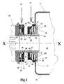
- Figure 2 is a enlarged view of the combustion chamber mounting illustrated in Figure 1.
-
- With reference to Figure 1, a
combustion chamber 10 has acylindrical wall 11 of which thedownstream end 12 is radially located within atransition duct 13 arranged in known manner to conduct the combustion gases to a compressor turbine and, if appropriate, a power turbine. A pistonring sliding seal 14 is axially located by an internalannular groove 15 formed in thetransition duct 13 to permit limited relative axial movement between thecombustion chamber 10 and thetransition duct 13 in the direction of the cylindrical axis X-X. Theupstream end 16 of thecombustion chamber 10 is partially closed by an integralradial wall 17 formed with acircular aperture 18 which is preferably coaxial with the axis X-X. Although thewall 17 is illustrated as extending in a radial plane, it may instead be frusto-conical or of another configuration provided that it defines spaced-apart inner andouter surfaces aperture 18. In the event that thewall 17 is frusto-conical, it is advantageous for the portions of the inner andouter surfaces aperture 18 to be radial. - The
combustion chamber 10 is formed from an appropriate ceramic material, for instance, woven continuous fibres embedded in a silicon carbide matrix. If desired, a thermal insulation layer may be fixed to the internal surfaces of the combustion chamber. However, the combustion chamber could instead be made of any suitable material. - The
radial wall 17 is secured by a first attachment means 21 to atubular mounting 22 which is in turn secured by a second attachment means 23 to asupport structure 24 in the form of an inlet guide vane. Thesupport structure 24 is rigidly mounted from an unshown engine housing and serves both to support themounting 22, and to direct a flow of air from the compressor into themounting 22 which also acts as a housing for an unshown fuel burner. The second attachment means 23 therefore attaches themounting 22 to thesupport structure 24 and constitutes a support structure attachment for themounting 22. The first attachment means 21 attaches themounting 22 to thecombustion chamber 10 and constitutes a combustion chamber attachment for themounting 22. - The construction and operation of the first attachment means 21, the
mounting 22 and the second attachment means 23 are now described with reference to Figure 2 which shows the various components to a larger scale. - From Figure 2 it will be noted that the external cylindrical surface of the
mounting 22 is formed externally with a first series oflongitudinal slots 25 for mounting the first attachment means 21, and with a second series oflongitudinal slots 26 for mounting the second attachment means 23. The external cylindrical surface of themounting 22 is also formed with ascrew thread 27. - The first attachment means 21 comprises a downstream or
inner clamp plate 28, an upstream orouter clamp plate 29, alocking nut 30, alock washer 31 and a biasing means in the form of a frusto-conical, or Belleville,spring 32. Theinner clamp plate 28 has an internal screw thread engaging thescrew thread 27 and is thereby secured radially to themounting 22 whilst permitting relative axial adjustment. Theinner clamp plate 28 defines aspigot 33 which fits, as illustrated, within the slightly larger diameter of thecircular aperture 18, leaving a clearance C whose size relative to adjacent components is shown exaggerated for clarity of illustration. Thecombustion chamber 10 is thereby located radially from both theinner clamp plate 28 and themounting 22, with clearance C allowing for limited differential radial movement (expansion or contraction) between theceramic combustor wall 17 and the combination of themounting 22 and the attachment means 21. Thecombustion chamber 10 is axially located, relative to themounting 22, by aclamp surface 34 which is defined by theinner clamp plate 28 and abuts theinner surface 19 of theradial wall 17, the relative axial position of the combustion chamberlO being adjustable by rotating theinner clamp plate 28 relative to themounting 22. Thelock washer 31 is formed with inwardly directedintegral tangs 35 which engage the first series oflongitudinal slots 25, thereby preventing relative rotation between thelock washer 31 and themounting 22 whilst permitting relative axial movement. When theinner clamp plate 28 has been adjusted to the required axial position, it is axially secured to themounting 22 by sliding thelocking washer 31 to the right, as seen in Figure 2, until axially-directed pins orprojections 36, formed integral with theinner clamp plate 28, are engaged within radial slots 37 formed through thelocking washer 31. - The
outer clamp plate 29 is mounted, for axial movement, on acylindrical hub 38 formed integral with theinner clamp plate 28, and defines asecond clamp surface 39 which abuts theouter surface 20 of theradial wall 17. In this manner, the inner andouter surfaces radial wall 17 are gripped between the clamp surfaces 34, 39 under the action of thespring 32, thereby securing thecombustion chamber 10 axially to the mounting 22. The lockingnut 30 is also mounted on thescrew thread 27 so that the force exerted by thespring 32 can be adjusted to a desired value by rotating the lockingnut 30 relative to the mounting 22. After such adjustment, the lockingnut 30 is secured to the lockingwasher 31 by known means, for example, either by wiring, or by deforming an outer edge portion of the lockingwasher 31 into an unshown detent in the adjacent peripheral edge of the lockingnut 30. It will be noted that the lockingnut 30 additionally serves to retain the lockingwasher 31 in engagement with thepins 36. Thespring 32 is located by anannular lip 40 formed integral with theouter clamp plate 29. - In addition to securing the
combustion chamber 10 to the mounting 22, the first attachment means 21 is designed to permit differential radial movement between theradial wall 17 and theclamp plates spring 32 to permit radial slippage between theclamp plates surfaces radial wall 17, thereby limiting the stresses that would otherwise have arisen due to radial expansion or contraction of thecombustion chamber 10 relative to the first attachment means 21. This slippage is enhanced by coating the clamp surfaces 34, 39 with an abradable material such as that marketed under the designation METCO 314 NS. As thesurfaces ceramic surfaces ceramic surfaces radial wall 17. Other surface treatments may be used to reduce the friction between the clamp surfaces 34, 39 and the inner andouter walls - The second attachment means 23 comprises a
clamp ring 41, a lockingring 42, a biasing means in the form of a frusto-conical spring 43, aspacer 44, and a series ofbolts 45 which pass through and secure theclamp ring 41, the lockingring 42 and thespacer 44 to the support structure provided by thesupport structure 24. - The second series of
longitudinal slots 26 engagetangs 46 formed integral with the lockingring 42, thereby preventing rotation of the mounting 22 relative to thesupport structure 24. The left-hand end of the tubular mounting 22 is enlarged, as shown, and is retained by an inwardly-directedannular flange 47 which is formed integral with the clampingring 41 and resists the net axial combustion force applied to thecombustion chamber 10. - The
spring 43 reacts between thesupport structure 24 and the left-hand end of the mounting 22 with a force determined by the spring rating and the thickness of thespacer 44. In this manner, the mounting 22 and the attachedcombustion chamber 10 are located axially in the position shown in Figure 2, whilst thespring 43 permits tilting movement of thecombustion chamber 10 relative to thesupport structure 24; such tilting movement being caused by differential thermal movement between itsdownstream end 12 and itsupstream end 16. The rating ofspring 43 is chosen to be less than that ofspring 32 to ensure that such tilting is only permitted in the region ofspring 43. Thus,spring 32 accommodates only differential radial movement whilstspring 43 permits only tilting movement, the ratings of these springs being chosen to limit the stresses within the material forming thecombustion chamber 10 to an acceptable level. - A working
clearance 48 is provided between theflange 47 and the outer diameter of the mounting 22 to accommodate the required range of tilting movement of the mounting 22 relative to thesupport structure 24. - By way of an overview of the working of the above-described assembly, it may be noted that the first attachment means 21 accommodates limited differential radial movement between the
combustion chamber 10 and the mounting 22 in that thespring 32 biases themembers combustor wall 17 between them in radially slideable fashion while simultaneously restraining axial movement of the combustor relative to the mounting 22. At the same time, the second attachment means 23 permits the mounting 22 (and hence the combustion chamber) to tilt a limited amount relative to thesupport structure 24, in that thespring 43 biases these two components apart by exerting a separation force between them, while simultaneously restraining relative radial movement between them, due to the abutment of the radially inner and outer edges of thespring 43 against the mounting 22 and thespacer 44 respectively. - Although the
springs - In view of the high firing temperature within the
combustion chamber 10, it may be necessary to cool at least some of the components of the first and second attachment means 21, 23 and the mounting 22. This can be achieved by arranging air passages in appropriate locations through the mounting. - In addition to controlling the level of stresses caused by thermal expansion and contraction, it should be noted that the axial forces exerted by the
springs combustion chamber 10 and the range of the residual axial force exerted on thecombustion chamber 10, to ensure that the system will not vibrate.
Claims (16)
- A gas turbine engine having a combustion chamber (10) secured to a mounting (22) by a first attachment means (21) arranged to accommodate differential radial movement between the combustion chamber and the mounting, characterised in that the mounting is secured to a support structure (24) by a second attachment means (23) arranged to permit the combustion chamber (10) to tilt relative to the support structure (24).
- A gas turbine engine according to Claim 1, in which the first attachment means extends through an aperture in a wall of the combustion chamber and defines a pair of opposed surfaces shaped respectively to engage inner and outer surfaces of the combustion chamber wall adjacent the aperture, and the first attachment means also includes a biasing means operative to cause the opposed surfaces to grip the inner and outer surfaces of the combustion chamber wall with a force sufficient to secure the combustion chamber to the mounting whilst permitting differential radial movement between the combustion chamber wall and the opposed surfaces.
- A gas turbine engine according to Claim 2, in which one of the opposed surfaces is defined by a first member that is axially secured to the mounting, the other opposed surface is defined by a second member that is mounted for axial movement relative to the mounting, and the biasing means is arranged to react between the mounting and the second member.
- A gas turbine engine according to Claim 3, including an axial adjustment device arranged operatively between the first member and the mounting to enable the position of the said one opposed surface to be adjusted axially of the mounting.
- A gas turbine engine according to Claim 3 or 4, in which the first member is positioned within the combustion chamber.
- A gas turbine engine according to any preceding claim, in which the second attachment means includes a second biasing device operative to oppose movement of the mounting relative to the support structure.
- A gas turbine engine according to any preceding claim, in which the mounting is tubular and surrounds a fuel burner.
- A gas turbine engine according to Claim 7, in which the support structure is an air inlet guide vane communicating with the combustion chamber through the tubular mounting.
- A gas turbine engine according to any preceding claim, in which the mounting includes at least one duct for the passage of cooling air.
- A gas turbine engine according to any preceding claim, in which the combustion chamber is formed of a ceramic material.
- A gas turbine engine according to Claim 10, in which the ceramic material comprises woven continuous fibres embedded in a silicon carbide matrix.
- A gas turbine engine according to Claim 10 or 11, in which surfaces of the first attachment means that are to contact the ceramic combustion chamber are coated with an abradable metallic material.
- A combustion chamber mounting (22) having a first attachment means (21) for securing a combustion chamber (10) to the mounting, said first attachment means being capable of accommodating limited differential radial movement between the combustion chamber and the mounting, the mounting (22) being characterised by a second attachment means (23) for securing the mounting to a support structure (24), said second attachment means being capable of permitting the mounting, and hence the combustion chamber, to tilt a limited amount relative to the support structure (24).
- A combustion chamber mounting according to claim 13 in which the first and second attachment means comprise respective first and second bias means (28,30,32 and 41-44), the first bias means being arranged to restrain axial movement of the combustor relative to the mounting and the second bias means being arranged to restrain radial movement of the mounting relative to the support structure.
- A combustion chamber mounting according to claim 14, in which the first bias means includes a pair of clamp members (28, 30), the clamp members being urged together by spring means (32) to grip a wall of the combustor therebetween.
- A combustion chamber mounting according to claim 14 or claim 15, in which the second bias means includes spring means (43) for exerting a separation force between the support structure (24) and the mounting (22).
Applications Claiming Priority (2)
| Application Number | Priority Date | Filing Date | Title |
|---|---|---|---|
| GB9925296 | 1999-10-27 | ||
| GB9925296A GB2355784B (en) | 1999-10-27 | 1999-10-27 | Gas turbine |
Publications (2)
| Publication Number | Publication Date |
|---|---|
| EP1096207A1 true EP1096207A1 (en) | 2001-05-02 |
| EP1096207B1 EP1096207B1 (en) | 2006-12-20 |
Family
ID=10863390
Family Applications (1)
| Application Number | Title | Priority Date | Filing Date |
|---|---|---|---|
| EP00309526A Expired - Lifetime EP1096207B1 (en) | 1999-10-27 | 2000-10-27 | Combustor mounting for a gas turbine engine |
Country Status (4)
| Country | Link |
|---|---|
| US (1) | US6453675B1 (en) |
| EP (1) | EP1096207B1 (en) |
| DE (1) | DE60032440T2 (en) |
| GB (1) | GB2355784B (en) |
Cited By (4)
| Publication number | Priority date | Publication date | Assignee | Title |
|---|---|---|---|---|
| WO2004055439A1 (en) * | 2002-12-18 | 2004-07-01 | Pratt & Whitney Canada Corp. | Low cost combustor floating collar with improved sealing and damping |
| EP1719949A2 (en) | 2005-04-27 | 2006-11-08 | United Technologies Corporation | Compliant metal support for ceramic combustor liner in a gas turbine engine |
| FR2911666A1 (en) * | 2007-01-18 | 2008-07-25 | Snecma Sa | Air and liquid fuel mixture injecting device for e.g. jet engine, of aircraft, has dampening washer inserted in housing, where washer is in contact with annular flange of sliding crosspiece and upstream and downstream wall of housing |
| WO2016096388A1 (en) * | 2014-12-15 | 2016-06-23 | Nuovo Pignone Srl | Combustor liner flexible support and method |
Families Citing this family (24)
| Publication number | Priority date | Publication date | Assignee | Title |
|---|---|---|---|---|
| US6895757B2 (en) * | 2003-02-10 | 2005-05-24 | General Electric Company | Sealing assembly for the aft end of a ceramic matrix composite liner in a gas turbine engine combustor |
| US7007480B2 (en) * | 2003-04-09 | 2006-03-07 | Honeywell International, Inc. | Multi-axial pivoting combustor liner in gas turbine engine |
| US6931855B2 (en) * | 2003-05-12 | 2005-08-23 | Siemens Westinghouse Power Corporation | Attachment system for coupling combustor liners to a carrier of a turbine combustor |
| US7338244B2 (en) * | 2004-01-13 | 2008-03-04 | Siemens Power Generation, Inc. | Attachment device for turbine combustor liner |
| US7134286B2 (en) * | 2004-08-24 | 2006-11-14 | Pratt & Whitney Canada Corp. | Gas turbine floating collar arrangement |
| US7140189B2 (en) * | 2004-08-24 | 2006-11-28 | Pratt & Whitney Canada Corp. | Gas turbine floating collar |
| US7581402B2 (en) * | 2005-02-08 | 2009-09-01 | Siemens Energy, Inc. | Turbine engine combustor with bolted swirlers |
| US8769963B2 (en) * | 2007-01-30 | 2014-07-08 | Siemens Energy, Inc. | Low leakage spring clip/ring combinations for gas turbine engine |
| US7926280B2 (en) * | 2007-05-16 | 2011-04-19 | Pratt & Whitney Canada Corp. | Interface between a combustor and fuel nozzle |
| US8104291B2 (en) * | 2008-03-27 | 2012-01-31 | General Electric Company | Combustion cap floating collar using E-seal |
| US8863527B2 (en) * | 2009-04-30 | 2014-10-21 | Rolls-Royce Corporation | Combustor liner |
| US9234431B2 (en) * | 2010-07-20 | 2016-01-12 | Siemens Energy, Inc. | Seal assembly for controlling fluid flow |
| US8919137B2 (en) * | 2011-08-05 | 2014-12-30 | General Electric Company | Assemblies and apparatus related to integrating late lean injection into combustion turbine engines |
| US8893382B2 (en) | 2011-09-30 | 2014-11-25 | General Electric Company | Combustion system and method of assembling the same |
| US8459041B2 (en) * | 2011-11-09 | 2013-06-11 | General Electric Company | Leaf seal for transition duct in turbine system |
| US9212556B2 (en) | 2012-08-21 | 2015-12-15 | United Technologies Corporation | Multifunction positioning lock washer |
| US9097130B2 (en) * | 2012-09-13 | 2015-08-04 | General Electric Company | Seal for use between injector and combustion chamber in gas turbine |
| US9175855B2 (en) * | 2012-10-29 | 2015-11-03 | General Electric Company | Combustion nozzle with floating aft plate |
| US9759427B2 (en) * | 2013-11-01 | 2017-09-12 | General Electric Company | Interface assembly for a combustor |
| DE102014204481A1 (en) | 2014-03-11 | 2015-09-17 | Rolls-Royce Deutschland Ltd & Co Kg | Combustion chamber of a gas turbine |
| DE102014204476A1 (en) * | 2014-03-11 | 2015-10-01 | Rolls-Royce Deutschland Ltd & Co Kg | Combustion chamber of a gas turbine |
| FR3040765B1 (en) * | 2015-09-09 | 2017-09-29 | Snecma | SUPPORTING ELEMENT FOR DAMPING AXIAL MOVEMENTS OF SLIDING INJECTION SYSTEM FOR TURBOMACHINE |
| US10429070B2 (en) * | 2016-02-25 | 2019-10-01 | General Electric Company | Combustor assembly |
| US11506384B2 (en) * | 2019-02-22 | 2022-11-22 | Dyc Turbines | Free-vortex combustor |
Citations (4)
| Publication number | Priority date | Publication date | Assignee | Title |
|---|---|---|---|---|
| US3999376A (en) * | 1973-07-05 | 1976-12-28 | Ford Motor Company | One-piece ceramic support housing for a gas turbine with a rotary regenerator |
| GB1476414A (en) | 1974-04-05 | 1977-06-16 | Gen Motors Corp | Combustion apparatus for a gas turbine engine |
| US4454711A (en) * | 1981-10-29 | 1984-06-19 | Avco Corporation | Self-aligning fuel nozzle assembly |
| JPH05118549A (en) * | 1991-10-25 | 1993-05-14 | Nissan Motor Co Ltd | Burner for gas turbine |
Family Cites Families (7)
| Publication number | Priority date | Publication date | Assignee | Title |
|---|---|---|---|---|
| US4365470A (en) * | 1980-04-02 | 1982-12-28 | United Technologies Corporation | Fuel nozzle guide and seal for a gas turbine engine |
| US4322945A (en) * | 1980-04-02 | 1982-04-06 | United Technologies Corporation | Fuel nozzle guide heat shield for a gas turbine engine |
| US4363208A (en) * | 1980-11-10 | 1982-12-14 | General Motors Corporation | Ceramic combustor mounting |
| GB2147405A (en) * | 1983-09-28 | 1985-05-09 | Rolls Royce | Gas turbine engine combustion chamber mounting |
| WO1994020790A1 (en) * | 1993-03-01 | 1994-09-15 | Engelhard Corporation | Improved catalytic combustion system including a separator body |
| US5592814A (en) * | 1994-12-21 | 1997-01-14 | United Technologies Corporation | Attaching brittle composite structures in gas turbine engines for resiliently accommodating thermal expansion |
| US5840221A (en) * | 1996-12-02 | 1998-11-24 | Saint-Gobain/Norton Industrial Ceramics Corporation | Process for making silicon carbide reinforced silicon carbide composite |
-
1999
- 1999-10-27 GB GB9925296A patent/GB2355784B/en not_active Expired - Lifetime
-
2000
- 2000-10-27 DE DE60032440T patent/DE60032440T2/en not_active Expired - Fee Related
- 2000-10-27 EP EP00309526A patent/EP1096207B1/en not_active Expired - Lifetime
- 2000-10-27 US US09/699,066 patent/US6453675B1/en not_active Expired - Fee Related
Patent Citations (4)
| Publication number | Priority date | Publication date | Assignee | Title |
|---|---|---|---|---|
| US3999376A (en) * | 1973-07-05 | 1976-12-28 | Ford Motor Company | One-piece ceramic support housing for a gas turbine with a rotary regenerator |
| GB1476414A (en) | 1974-04-05 | 1977-06-16 | Gen Motors Corp | Combustion apparatus for a gas turbine engine |
| US4454711A (en) * | 1981-10-29 | 1984-06-19 | Avco Corporation | Self-aligning fuel nozzle assembly |
| JPH05118549A (en) * | 1991-10-25 | 1993-05-14 | Nissan Motor Co Ltd | Burner for gas turbine |
Non-Patent Citations (1)
| Title |
|---|
| PATENT ABSTRACTS OF JAPAN vol. 017, no. 490 (M - 1474) 6 September 1993 (1993-09-06) * |
Cited By (10)
| Publication number | Priority date | Publication date | Assignee | Title |
|---|---|---|---|---|
| WO2004055439A1 (en) * | 2002-12-18 | 2004-07-01 | Pratt & Whitney Canada Corp. | Low cost combustor floating collar with improved sealing and damping |
| US6880341B2 (en) | 2002-12-18 | 2005-04-19 | Pratt & Whitney Canada Corp. | Low cost combustor floating collar with improved sealing and damping |
| EP1719949A2 (en) | 2005-04-27 | 2006-11-08 | United Technologies Corporation | Compliant metal support for ceramic combustor liner in a gas turbine engine |
| EP1719949A3 (en) * | 2005-04-27 | 2009-09-02 | United Technologies Corporation | Compliant metal support for ceramic combustor liner in a gas turbine engine |
| US7647779B2 (en) | 2005-04-27 | 2010-01-19 | United Technologies Corporation | Compliant metal support for ceramic combustor liner in a gas turbine engine |
| US8122727B2 (en) | 2005-04-27 | 2012-02-28 | United Technologies Corporation | Compliant metal support for ceramic combustor liner in a gas turbine engine |
| FR2911666A1 (en) * | 2007-01-18 | 2008-07-25 | Snecma Sa | Air and liquid fuel mixture injecting device for e.g. jet engine, of aircraft, has dampening washer inserted in housing, where washer is in contact with annular flange of sliding crosspiece and upstream and downstream wall of housing |
| WO2016096388A1 (en) * | 2014-12-15 | 2016-06-23 | Nuovo Pignone Srl | Combustor liner flexible support and method |
| US20170350599A1 (en) * | 2014-12-15 | 2017-12-07 | Nuovo Pignone Srl | Combustor liner flexible support and method |
| US11333361B2 (en) | 2014-12-15 | 2022-05-17 | Nuovo Pignone Srl | Combustor liner flexible support and method |
Also Published As
| Publication number | Publication date |
|---|---|
| GB9925296D0 (en) | 1999-12-29 |
| DE60032440D1 (en) | 2007-02-01 |
| DE60032440T2 (en) | 2007-04-26 |
| EP1096207B1 (en) | 2006-12-20 |
| GB2355784A (en) | 2001-05-02 |
| US6453675B1 (en) | 2002-09-24 |
| GB2355784B (en) | 2004-05-05 |
Similar Documents
| Publication | Publication Date | Title |
|---|---|---|
| US6453675B1 (en) | Combustor mounting for gas turbine engine | |
| US6758653B2 (en) | Ceramic matrix composite component for a gas turbine engine | |
| EP1013885B1 (en) | Turbine vane mounting arrangement | |
| US6655148B2 (en) | Fixing metal caps onto walls of a CMC combustion chamber in a turbomachine | |
| EP1564494B1 (en) | Fixing system of a flame pipe or liner | |
| US8424312B2 (en) | Exhaust system for gas turbine | |
| CA2680117C (en) | Method for assembling end-to-end two parts having different thermal expansion coefficients and assembly thus obtained | |
| US12270544B2 (en) | Combustor assembly for a turbine engine | |
| US20170248320A1 (en) | Combustor Assembly | |
| CA2952639C (en) | Combustor assembly | |
| EP1777461B1 (en) | Attachement of a ceramic combustor can | |
| KR20120044949A (en) | Exhaust-gas-turbine casing | |
| JP2006349336A (en) | Assembly of annular combustion chamber for turbo-machinery | |
| JP2544087B2 (en) | Thermal shield and support structure assembly for a gas turbine engine and divergent seal for a gas turbine engine exhaust nozzle | |
| EP3211312B1 (en) | Combustor assembly | |
| US7168253B1 (en) | Monobloc flameholder arm for an afterburner device of a bypass turbojet | |
| JP6622826B2 (en) | Turbine engine heat seal | |
| JPH0696986B2 (en) | Engine parts mounting device | |
| US12071856B2 (en) | Assembly for a turbomachine turbine | |
| KR102616048B1 (en) | Resonator, resonator manufacturing method and combustor arrangement provided with resonator |
Legal Events
| Date | Code | Title | Description |
|---|---|---|---|
| PUAI | Public reference made under article 153(3) epc to a published international application that has entered the european phase |
Free format text: ORIGINAL CODE: 0009012 |
|
| AK | Designated contracting states |
Kind code of ref document: A1 Designated state(s): DE ES FR GB IT |
|
| AX | Request for extension of the european patent |
Free format text: AL;LT;LV;MK;RO;SI |
|
| 17P | Request for examination filed |
Effective date: 20010918 |
|
| AKX | Designation fees paid |
Free format text: DE ES FR GB IT |
|
| 17Q | First examination report despatched |
Effective date: 20040812 |
|
| GRAP | Despatch of communication of intention to grant a patent |
Free format text: ORIGINAL CODE: EPIDOSNIGR1 |
|
| RAP1 | Party data changed (applicant data changed or rights of an application transferred) |
Owner name: ALSTOM TECHNOLOGY LTD |
|
| GRAS | Grant fee paid |
Free format text: ORIGINAL CODE: EPIDOSNIGR3 |
|
| GRAA | (expected) grant |
Free format text: ORIGINAL CODE: 0009210 |
|
| RBV | Designated contracting states (corrected) |
Designated state(s): DE ES FR GB IT |
|
| AK | Designated contracting states |
Kind code of ref document: B1 Designated state(s): DE FR |
|
| RBV | Designated contracting states (corrected) |
Designated state(s): DE FR |
|
| REF | Corresponds to: |
Ref document number: 60032440 Country of ref document: DE Date of ref document: 20070201 Kind code of ref document: P |
|
| ET | Fr: translation filed | ||
| PLBE | No opposition filed within time limit |
Free format text: ORIGINAL CODE: 0009261 |
|
| STAA | Information on the status of an ep patent application or granted ep patent |
Free format text: STATUS: NO OPPOSITION FILED WITHIN TIME LIMIT |
|
| 26N | No opposition filed |
Effective date: 20070921 |
|
| PGFP | Annual fee paid to national office [announced via postgrant information from national office to epo] |
Ref country code: DE Payment date: 20081009 Year of fee payment: 9 |
|
| PGFP | Annual fee paid to national office [announced via postgrant information from national office to epo] |
Ref country code: FR Payment date: 20081013 Year of fee payment: 9 |
|
| REG | Reference to a national code |
Ref country code: FR Ref legal event code: ST Effective date: 20100630 |
|
| PG25 | Lapsed in a contracting state [announced via postgrant information from national office to epo] |
Ref country code: DE Free format text: LAPSE BECAUSE OF NON-PAYMENT OF DUE FEES Effective date: 20100501 Ref country code: FR Free format text: LAPSE BECAUSE OF NON-PAYMENT OF DUE FEES Effective date: 20091102 |