EP1096127A2 - Cylinder liners for aluminium motor blocks and methods of production - Google Patents
Cylinder liners for aluminium motor blocks and methods of production Download PDFInfo
- Publication number
- EP1096127A2 EP1096127A2 EP00122083A EP00122083A EP1096127A2 EP 1096127 A2 EP1096127 A2 EP 1096127A2 EP 00122083 A EP00122083 A EP 00122083A EP 00122083 A EP00122083 A EP 00122083A EP 1096127 A2 EP1096127 A2 EP 1096127A2
- Authority
- EP
- European Patent Office
- Prior art keywords
- liner
- mold
- iron
- piston
- aluminum
- Prior art date
- Legal status (The legal status is an assumption and is not a legal conclusion. Google has not performed a legal analysis and makes no representation as to the accuracy of the status listed.)
- Withdrawn
Links
- 229910052782 aluminium Inorganic materials 0.000 title claims abstract description 63
- XAGFODPZIPBFFR-UHFFFAOYSA-N aluminium Chemical compound [Al] XAGFODPZIPBFFR-UHFFFAOYSA-N 0.000 title claims abstract description 62
- 238000000034 method Methods 0.000 title claims abstract description 27
- 238000004519 manufacturing process Methods 0.000 title abstract description 11
- 239000004411 aluminium Substances 0.000 title 1
- XEEYBQQBJWHFJM-UHFFFAOYSA-N Iron Chemical compound [Fe] XEEYBQQBJWHFJM-UHFFFAOYSA-N 0.000 claims abstract description 128
- 229910052742 iron Inorganic materials 0.000 claims abstract description 63
- 229910001018 Cast iron Inorganic materials 0.000 claims abstract description 14
- 238000007711 solidification Methods 0.000 claims abstract description 9
- 230000008023 solidification Effects 0.000 claims abstract description 9
- 238000002485 combustion reaction Methods 0.000 claims abstract description 7
- 238000000465 moulding Methods 0.000 claims abstract description 7
- 238000003780 insertion Methods 0.000 claims abstract description 6
- 230000037431 insertion Effects 0.000 claims abstract description 6
- 239000000126 substance Substances 0.000 claims abstract description 6
- 230000001747 exhibiting effect Effects 0.000 claims abstract 2
- 239000010410 layer Substances 0.000 claims description 19
- 238000005266 casting Methods 0.000 claims description 12
- VYPSYNLAJGMNEJ-UHFFFAOYSA-N Silicium dioxide Chemical compound O=[Si]=O VYPSYNLAJGMNEJ-UHFFFAOYSA-N 0.000 claims description 9
- 239000002344 surface layer Substances 0.000 claims description 9
- 229910052751 metal Inorganic materials 0.000 claims description 7
- 239000002184 metal Substances 0.000 claims description 7
- 238000012545 processing Methods 0.000 claims description 6
- 239000011148 porous material Substances 0.000 claims description 4
- 238000012546 transfer Methods 0.000 claims description 4
- 230000013011 mating Effects 0.000 claims description 3
- 239000000203 mixture Substances 0.000 claims description 3
- 239000004576 sand Substances 0.000 claims description 3
- 239000007921 spray Substances 0.000 claims description 3
- XLYOFNOQVPJJNP-UHFFFAOYSA-N water Substances O XLYOFNOQVPJJNP-UHFFFAOYSA-N 0.000 claims description 3
- 239000000440 bentonite Substances 0.000 claims description 2
- 229910000278 bentonite Inorganic materials 0.000 claims description 2
- SVPXDRXYRYOSEX-UHFFFAOYSA-N bentoquatam Chemical compound O.O=[Si]=O.O=[Al]O[Al]=O SVPXDRXYRYOSEX-UHFFFAOYSA-N 0.000 claims description 2
- 239000003599 detergent Substances 0.000 claims description 2
- 235000013312 flour Nutrition 0.000 claims description 2
- 238000003754 machining Methods 0.000 claims description 2
- 239000000377 silicon dioxide Substances 0.000 claims description 2
- 229910001315 Tool steel Inorganic materials 0.000 claims 1
- 238000006243 chemical reaction Methods 0.000 claims 1
- 239000012141 concentrate Substances 0.000 claims 1
- 238000001816 cooling Methods 0.000 claims 1
- 238000007373 indentation Methods 0.000 claims 1
- 238000005507 spraying Methods 0.000 claims 1
- 239000011159 matrix material Substances 0.000 abstract description 2
- KCZFLPPCFOHPNI-UHFFFAOYSA-N alumane;iron Chemical compound [AlH3].[Fe] KCZFLPPCFOHPNI-UHFFFAOYSA-N 0.000 description 6
- 230000008018 melting Effects 0.000 description 4
- 238000002844 melting Methods 0.000 description 4
- 238000010586 diagram Methods 0.000 description 2
- 238000005406 washing Methods 0.000 description 2
- CYUOWZRAOZFACA-UHFFFAOYSA-N aluminum iron Chemical compound [Al].[Fe] CYUOWZRAOZFACA-UHFFFAOYSA-N 0.000 description 1
- -1 aluminum metals Chemical class 0.000 description 1
- 238000010420 art technique Methods 0.000 description 1
- 230000015572 biosynthetic process Effects 0.000 description 1
- 239000012530 fluid Substances 0.000 description 1
- 238000007429 general method Methods 0.000 description 1
- 230000006698 induction Effects 0.000 description 1
- 238000011081 inoculation Methods 0.000 description 1
- 238000007689 inspection Methods 0.000 description 1
- 238000005495 investment casting Methods 0.000 description 1
- 150000002739 metals Chemical class 0.000 description 1
- 238000002360 preparation method Methods 0.000 description 1
- 238000010079 rubber tapping Methods 0.000 description 1
- 239000007787 solid Substances 0.000 description 1
Images

Classifications
-
- F—MECHANICAL ENGINEERING; LIGHTING; HEATING; WEAPONS; BLASTING
- F02—COMBUSTION ENGINES; HOT-GAS OR COMBUSTION-PRODUCT ENGINE PLANTS
- F02F—CYLINDERS, PISTONS OR CASINGS, FOR COMBUSTION ENGINES; ARRANGEMENTS OF SEALINGS IN COMBUSTION ENGINES
- F02F1/00—Cylinders; Cylinder heads
- F02F1/02—Cylinders; Cylinder heads having cooling means
- F02F1/10—Cylinders; Cylinder heads having cooling means for liquid cooling
- F02F1/16—Cylinder liners of wet type
-
- F—MECHANICAL ENGINEERING; LIGHTING; HEATING; WEAPONS; BLASTING
- F02—COMBUSTION ENGINES; HOT-GAS OR COMBUSTION-PRODUCT ENGINE PLANTS
- F02B—INTERNAL-COMBUSTION PISTON ENGINES; COMBUSTION ENGINES IN GENERAL
- F02B3/00—Engines characterised by air compression and subsequent fuel addition
- F02B3/06—Engines characterised by air compression and subsequent fuel addition with compression ignition
-
- Y—GENERAL TAGGING OF NEW TECHNOLOGICAL DEVELOPMENTS; GENERAL TAGGING OF CROSS-SECTIONAL TECHNOLOGIES SPANNING OVER SEVERAL SECTIONS OF THE IPC; TECHNICAL SUBJECTS COVERED BY FORMER USPC CROSS-REFERENCE ART COLLECTIONS [XRACs] AND DIGESTS
- Y10—TECHNICAL SUBJECTS COVERED BY FORMER USPC
- Y10T—TECHNICAL SUBJECTS COVERED BY FORMER US CLASSIFICATION
- Y10T29/00—Metal working
- Y10T29/49—Method of mechanical manufacture
- Y10T29/49229—Prime mover or fluid pump making
- Y10T29/4927—Cylinder, cylinder head or engine valve sleeve making
- Y10T29/49272—Cylinder, cylinder head or engine valve sleeve making with liner, coating, or sleeve
Definitions
- This invention relates to iron-aluminum bimetallic liners for combustion engines, typically with aluminum motor blocks, and their manufacture, and more particularly it relates to bimetallic aluminum-iron cylinder liners and for producing the liners by casting methods bonding iron to aluminum.
- Cylinder liners are known in the art as typified by U.S. Patent Nos. 4,523,554 to H. Ryu, June 18, 1985 and 5,183,025 to J.L. Jorstad, et al, February 2, 1993. These liners interface thermal energy transfer between the piston and engine block. Cylinder liners are also known to have provisions for introducing fluid flow paths to control transfer of thermal energy from the pistons to the engine block.
- Another problem of producing the cylinder liners is the desire to have a roughened surface on the iron interface which contacts the aluminum engine block as a feature of handling thermal transfer of energy between the piston and the engine block.
- a generally hollow cylindrical piston liner for insertion in an internal combustion engine between a piston and an engine block has a cast aluminum piston liner body with a cast iron engine block contact surface member extending circumferentially from its outer cylindrical surface.
- a thin iron layer is securely thermally bonded to ribs extending from the liner body to exhibit a roughened motor block contact surface.
- the cast iron liner with the roughened surface is generated by introducing onto a mold cavity surface a mold wash substance that adheres to and forms a layer on the mold cavity surface and in the process of casting generates a substantially uniform bubble pattern to thereby produce a roughened iron interface surface of appropriate texture before molten iron is poured onto the wash layer.
- the aluminum piston liner is then bonded to the iron liner by pouring molten aluminum over the iron liner in a pre-heated piston liner mold. During the solidification stages, the molds are centrifugally rotated about the piston liner cylinder axis to establish the required manufacturing precision for large diameter piston liners.
- the piston liners have a series of circumferential ribs spaced proportionately along the liner length and these ribs are interfaced with the iron liner surfaces.
- a cast aluminum piston liner for insertion in an internal combustion engine between a piston and an engine block
- a hollow cylindrical cast aluminum liner body for receiving the piston having a plurality of spaced circumferential aluminum ribs extending from its outer surface for supporting a thermal contact iron interface surface between the cylindrical liner body and a mating surrounding engine block surface.
- the thermal contact surface is formed as a cast iron engine block contact member with a roughened outer surface, wherein the iron member is thermally bonded onto the circumferential aluminum ribs extending from the cylindrical liner body.
- the invention provides a method of molding the cylindrical cast aluminum piston liner having externally protruding aluminum ribs covered by a cast surface layer of iron roughened at the outer surface for interfacing the resident engine block surface. Molds are prepared and preheated, where necessary, before pouring the respective molten iron and aluminum metals in a sequence of corresponding casting steps.
- a layer of a mold wash substance is adhered to the mold inner surface to produce, before the pouring of molten iron into the mold, a mass of bubbles at the outer surface contact interface of the molten iron poured into the mold.
- the loaded molds are rotated about the cylindrical axis of the piston liner during solidification of molten metal.
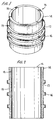
- FIGURES 1 and 2 the typical cylinder liner preferred embodiment 15 is set forth.
- the flange 14 is shown at the top of the liner 15.
- the size of the cylinder varies for different engines and it has been difficult in the prior art because of the difference in melting temperatures of iron and aluminum to produce any cylinder liner casting with a bonded-on iron surface member 16, as displayed on the outer circumference of the three symmetrically placed aluminum ribs 17 for establishing thermal surface contact interface within a receiving aluminum engine block.
- strict dimensional tolerances of cylindrical roundness are imposed which have been exceedingly difficult to achieve in cast products, particularly for larger diameter pistons such as used for Diesel engines for example.
- the manner of meeting such tolerances by rotating molds about the cylindrical axis of the liner is later discussed with respect to the precision casting process for manufacture of the cylinder liner afforded by this invention.
- the interface bonding of the iron surface member 16 onto the integrally extending and thus strongly affixed cast aluminum ribs 17 is critical because of the significantly different melting temperatures of iron and aluminum.
- the circumferential alignment of the aluminum ribs 17 presents the bonded iron surface members 16 perpendicular to the movement of the piston in the interior surface 18 of the aluminum liner body 15 to thus encounter high stresses at the interface surface between the liner body 15 and the aluminum engine block into which it is mounted.
- the bonding strength between the iron and aluminum components 16 and 17 provided in the casting process of this invention is a significant improvement in the art.
- FIGURE 3 is a flow diagram outlining the process of manufacturing the cast cylinder liners 15.
- the mold washing step 20 is critical in the formation of the roughened porous surface characteristics of the iron surface 16.
- the preferred wash constituency is obtained using a mixture of 25 pounds of silica flour, 200 mesh, with 0.875 pounds of western bentonite in 12 pounds of water with 3 ounces of concentrated detergent, typically Orvus brand marketed by Proctor & Gamble, is prepared at block 21 and verified at block 22.
- this mixture after being diluted by water to a viscosity range from 20 to 25 seconds, is then at block 20 washed upon the surface of the mold, which is then pre-heated to a processing temperature in the range of 140 to 160 degrees Centigrade in blocks 23 and 24.
- This wash being appropriately applied to a thickness of one millimeter on the mold surface at block 25 serves to generate a set of substantially uniformly distributed bubbles in a solid matrix pattern into which molten iron may be poured to produce its roughened, porous surface characteristic.
- the mold wash is applied to the internal mold surface by the use of a pressure tank and a spray nozzle.
- the appropriate bubble characteristics are controlled by the choice of air pressure, spray nozzle and the movement speed relative to the mold taking into account the mold rotation speed at block 26.
- the air bubbles formed in the dried wash surface provide a generally uniformly distributed pattern of pores. By pouring molten iron into the bubble formed pattern in the wash layer surface at pouring station 27, these pores are filled with iron to accordingly roughen the outer contact surface of the iron.
- the mold is rotated about the axis of the liner cylinder at a desired temperature range as accomplished in block 28. After solidification (29) the mold cools to room temperature at block 30. After inspection 31, the cooled casting is machined at 32 to establish the specified length, internal diameter and outside body diameter. Because of the rotation of the molds, the precision tolerances required without eccentricity at the thin iron layer outer contact surface are achieved.
- the melting is achieved by an electric induction furnace 36 or equivalent electric resistance furnace to provide a charge which has a verified chemical constituency and temperature (Block 37). Weight is controlled at block 38 for the tapping and ladle inoculation step at 39.
- the pouring process for aluminum cylinder liner block may be done in either a stationary sand or metallic mold, which is rotated at 28 during the solidification stage, piece shakeout and mold preparation at a controlled rotation rate.
- the method steps comprise:
- the pores on the outer surface of the iron rings may be filled with molten aluminum to strengthen the bond between the iron and aluminum.
Abstract
Description
- fabricating, preparing and washing metal or sand molds,
- preheating metal molds for the molding step,
- placement of sand cores into the mold,
- preheating iron liners made in the foregoing way for processing the surface layer of iron in a mold,
- pouring the molten aluminum,
- solidifying and shaking out the cast aluminum block.
- producing a roughened outer surface on the cast iron layer by introducing a mold wash substance that produces a mass of bubbles in surface contact with molten iron poured into the mold,
- placement of the iron liner into a piston mold for producing the aluminum piston liner and pouring aluminum after preheating the piston mold and iron liner, and
- rotating the loads about the cylindrical axis of the piston liner during solidification of molten metal.
Claims (22)
- A cast aluminum piston liner for insertion in an internal combustion engine between a piston and an engine block, comprising in combination:a generally cylindrical cast aluminum liner body for receiving a piston having a plurality of spaced circumferential aluminum ribs extending therefrom for supporting a circumferential thermal contact surface member between the liner body and a mating surrounding engine block surface, wherein said thermal contact surface member is formed as a cast iron engine block contact member with a roughened outer cast surface, and the cast iron member is thermally bonded onto the circumferential aluminum ribs.
- The piston liner of Claim 1 wherein said roughened outer surface further exhibits surface indentations extending a depth of substantially one millimeter into the iron member.
- The piston liner of Claim 2 wherein said roughened outer surface is machined to form a mating surface with said surrounding engine block surface.
- The piston liner of Claim 2 wherein said roughened outer surface presents a relatively insulating thermal transfer characteristic between the piston liner and the surrounding engine block.
- The piston liner of Claim 1 with said liner having a defined length and having said spaced aluminum ribs arranged symmetrically along the liner length.
- The piston liner of Claim 1 wherein said ribs extend a distance in the order of 4 to 5 millimeters outwardly from said liner body.
- The method of casting the piston liner defined in Claim 1 including the step of centrifugally rotating and cylindrical mold during solidification of the molded product to produce acceptable circumferential rib outer dimensional tolerances suitable for surface contact between the liner and engine block.
- The method of Claim 7 further comprising the step of internally finishing an interior surface of the mold for adhering thereto a mold wash layer of a thickness of substantially one millimeter, said wash layer having the property of introducing bubbles in a subsequent mold preheating step.
- The method of Claim 8 further comprising the step of adhering the wash layer to said interior finished surface of the mold comprising a mixture of 25 pounds of silica flour of 200 mesh, 0.875 pounds of western bentonite, 12 pounds of water and 3 ounces of a detergent concentrate.
- The method of Claim 8 further comprising the steps of preheating the mold before applying the wash layer to a temperature range of 140 to 160 degrees Centigrade, spraying the wash layer on the interior finished surface of the mold with controlled pressure, from a spray nozzle advanced at a controlled speed about the mold interior surface with the mold being rotated at a predetermined mold speed to provide a wash layer of predetermined thickness for a liner body of predetermined diameter.
- The method of Claim 8 further comprising the steps of pouring molten iron into the rotating mold to form an iron surface liner layer for adherence to internally disposed aluminum ribs of said piston liner, thereby forming said roughened outer surface by reaction of molten iron with said wash layer.
- The method of Claim 11 further comprising the steps of preheating the mold containing the iron surface layer to a temperature between 200 and 300 degrees Centigrade before pouring molten aluminum at a temperature around 700 degrees Centigrade into the rotating mold thereby to bond with the iron and aluminum surface layers and form said cylinder liner with the spaced circumferential ribs.
- The method of Claim 11 further comprising the step of filling the porous outer surface of the iron surface layer with molten aluminum.
- The method of Claim 11 further comprising the steps of cooling the mold to room temperature and removing the cast cylinder liner with the bonded iron surface layer.
- The method of Claim 14 further comprising the step of machining outer surface of the ribs to a predetermined outer diameter dimension.
- The method of Claim 7 wherein the mold is disposable sand mold.
- The method of Claim 7 wherein the mold comprises a tool steel mold and accompanying internal sand cores.
- The method of Claim 7 further comprising the steps of pouring molten aluminum and molten iron into a stationary mold.
- A method of molding a cylindrical cast aluminum piston liner having externally protruding aluminum ribs with corresponding cast surface layers of iron, comprising the steps of:preparing and preheating molds for each molding step,casting an iron liner to produce said surface layer of iron in a mold,producing a roughened outer surface on the cast iron layer by introducing a mold wash substance that produced a mass of bubbles in surface contact with molten iron poured into the mold,placement of the iron liner into a piston mold for producing the aluminum piston liner and pouring aluminum onto the iron liner after preheating the iron liner and mold, androtating said loads about the cylindrical axis of said piston liner during solidification of molten metal.
- A generally hollow cylindrical piston liner for insertion in an internal combustion engine between a piston and an engine block, comprising in combination: a cast aluminum piston liner body with a cast iron engine block contact surface member extending therefrom securely thermally bonded thereto and exhibiting a roughened contact surface.
- The piston liner of Claim 20 wherein said roughened contact surface comprises a substantially uniform pattern of pores into which is deposited molten aluminum.
- The method of forming a generally hollow cylindrical piston liner body for insertion in an internal combustion engine between a piston and an engine block at an interface surface by the steps of casting an iron surface liner into a mold processed to produce a roughened interface surface, and casting molten aluminum onto the iron surface liner thereby to form said interface surface in a mold for processing a generally aluminum liner body.
Applications Claiming Priority (2)
| Application Number | Priority Date | Filing Date | Title |
|---|---|---|---|
| US428926 | 1989-10-30 | ||
| US09/428,926 US6138630A (en) | 1999-10-28 | 1999-10-28 | Cylinder liners for aluminum motor blocks and methods of production |
Publications (2)
| Publication Number | Publication Date |
|---|---|
| EP1096127A2 true EP1096127A2 (en) | 2001-05-02 |
| EP1096127A3 EP1096127A3 (en) | 2002-02-06 |
Family
ID=23700999
Family Applications (1)
| Application Number | Title | Priority Date | Filing Date |
|---|---|---|---|
| EP00122083A Withdrawn EP1096127A3 (en) | 1999-10-28 | 2000-10-11 | Cylinder liners for aluminium motor blocks and methods of production |
Country Status (2)
| Country | Link |
|---|---|
| US (1) | US6138630A (en) |
| EP (1) | EP1096127A3 (en) |
Cited By (1)
| Publication number | Priority date | Publication date | Assignee | Title |
|---|---|---|---|---|
| CN109396583A (en) * | 2017-08-15 | 2019-03-01 | 通用汽车环球科技运作有限责任公司 | Method for being bonded in cylinder buss in the cylinder bore of vehicle motor body |
Families Citing this family (5)
| Publication number | Priority date | Publication date | Assignee | Title |
|---|---|---|---|---|
| JP2005520095A (en) * | 2001-12-18 | 2005-07-07 | デルフィ テクノロジーズ,インコーポレイティド | Opposed piston type internal combustion engine |
| AU2002332015A1 (en) * | 2001-12-18 | 2003-12-31 | Delphi Technologies, Inc. | Internal combustion engine using opposed pistons |
| US7464537B2 (en) * | 2005-04-04 | 2008-12-16 | United Technologies Corporation | Heat transfer enhancement features for a tubular wall combustion chamber |
| JP4584058B2 (en) * | 2005-07-08 | 2010-11-17 | トヨタ自動車株式会社 | Cylinder liner and manufacturing method thereof |
| US10161354B2 (en) * | 2016-07-18 | 2018-12-25 | Ford Global Technologies, Llc | Composite combustion engine |
Citations (2)
| Publication number | Priority date | Publication date | Assignee | Title |
|---|---|---|---|---|
| US4523554A (en) | 1982-10-22 | 1985-06-18 | Usui Kokusai Sangyo Kabushiki Kaisha | Metal and ceramic assembly |
| US5183025A (en) | 1991-10-07 | 1993-02-02 | Reynolds Metals Company | Engine block and cylinder liner assembly and method |
Family Cites Families (6)
| Publication number | Priority date | Publication date | Assignee | Title |
|---|---|---|---|---|
| US2062394A (en) * | 1934-11-27 | 1936-12-01 | Charles S Brown | Cylinder block for air cooled internal combustion engines |
| FR2413553A1 (en) * | 1978-01-03 | 1979-07-27 | Renault | INTERNAL COMBUSTION ENGINE SHIRT |
| US4926801A (en) * | 1987-12-22 | 1990-05-22 | Mack Trucks, Inc. | Wet/dry cylinder liner for high output engines |
| DE4116652C1 (en) * | 1991-05-22 | 1992-06-25 | Dr.Ing.H.C. F. Porsche Ag, 7000 Stuttgart, De | |
| US5749331A (en) * | 1992-03-23 | 1998-05-12 | Tecsyn, Inc. | Powdered metal cylinder liners |
| JPH10122034A (en) * | 1996-10-16 | 1998-05-12 | Toyota Motor Corp | Cylinder block for internal combustion engine and manufacture thereof |
-
1999
- 1999-10-28 US US09/428,926 patent/US6138630A/en not_active Expired - Fee Related
-
2000
- 2000-10-11 EP EP00122083A patent/EP1096127A3/en not_active Withdrawn
Patent Citations (2)
| Publication number | Priority date | Publication date | Assignee | Title |
|---|---|---|---|---|
| US4523554A (en) | 1982-10-22 | 1985-06-18 | Usui Kokusai Sangyo Kabushiki Kaisha | Metal and ceramic assembly |
| US5183025A (en) | 1991-10-07 | 1993-02-02 | Reynolds Metals Company | Engine block and cylinder liner assembly and method |
Cited By (1)
| Publication number | Priority date | Publication date | Assignee | Title |
|---|---|---|---|---|
| CN109396583A (en) * | 2017-08-15 | 2019-03-01 | 通用汽车环球科技运作有限责任公司 | Method for being bonded in cylinder buss in the cylinder bore of vehicle motor body |
Also Published As
| Publication number | Publication date |
|---|---|
| EP1096127A3 (en) | 2002-02-06 |
| US6138630A (en) | 2000-10-31 |
Similar Documents
| Publication | Publication Date | Title |
|---|---|---|
| US6615899B1 (en) | Method of casting a metal article having a thinwall | |
| US2756475A (en) | Investment mold and core assembly | |
| WO1998000251A1 (en) | Die casting employing soluble core | |
| US6138630A (en) | Cylinder liners for aluminum motor blocks and methods of production | |
| CN110640085A (en) | Investment casting process for hollow casting | |
| CN108889924A (en) | Ferromagnetic alloy vacuum casting short route casting method | |
| JPH05200485A (en) | Graphite casting mold | |
| GB2090780A (en) | Method and apparatus for squeeze casting piston with wear resistant insert | |
| JPH11104798A (en) | Magnesium molding and manufacture | |
| EP0625386B1 (en) | An investment casting process for producing castings | |
| MXPA00010185A (en) | Cylinder liners for aluminum motor blocks and methods of production | |
| CN110860658B (en) | Preparation method of wax mold gypsum core of cylindrical thin-wall complex component | |
| US6964292B2 (en) | Process of fabricating castings provided with inserts, with improved component/inset mechanical cohesion, and an insert usable in the process | |
| JPH0128667B2 (en) | ||
| KR100893960B1 (en) | Method for producing a light-alloy bearing bush with a rough external surface | |
| US5392841A (en) | Mounting expendable core in die cast die | |
| CN110523921A (en) | A kind of casting method | |
| JPS6224172B2 (en) | ||
| JPS58128245A (en) | Production of sand core for pressure casting | |
| KR20020055054A (en) | preparation method of high-pressure casting core and casting method of engine piston containing oil gallery | |
| JPS606909B2 (en) | Ceramics-metal composite and its manufacturing method | |
| KR100240581B1 (en) | Method of manufacturing power steering oil pump housing | |
| JPS6372465A (en) | Mold construction | |
| JPH09155523A (en) | Sleeve of die casting machine and production thereof | |
| JPH01107954A (en) | Lost form pattern casting method |
Legal Events
| Date | Code | Title | Description |
|---|---|---|---|
| PUAI | Public reference made under article 153(3) epc to a published international application that has entered the european phase |
Free format text: ORIGINAL CODE: 0009012 |
|
| AK | Designated contracting states |
Kind code of ref document: A2 Designated state(s): AT BE CH CY DE DK ES FI FR GB GR IE IT LI LU MC NL PT SE |
|
| AX | Request for extension of the european patent |
Free format text: AL;LT;LV;MK;RO;SI |
|
| PUAL | Search report despatched |
Free format text: ORIGINAL CODE: 0009013 |
|
| AK | Designated contracting states |
Kind code of ref document: A3 Designated state(s): AT BE CH CY DE DK ES FI FR GB GR IE IT LI LU MC NL PT SE |
|
| AX | Request for extension of the european patent |
Free format text: AL;LT;LV;MK;RO;SI |
|
| AKX | Designation fees paid | ||
| REG | Reference to a national code |
Ref country code: DE Ref legal event code: 8566 |
|
| STAA | Information on the status of an ep patent application or granted ep patent |
Free format text: STATUS: THE APPLICATION IS DEEMED TO BE WITHDRAWN |
|
| 18D | Application deemed to be withdrawn |
Effective date: 20020807 |