EP1096107A2 - Locking devices - Google Patents
Locking devices Download PDFInfo
- Publication number
- EP1096107A2 EP1096107A2 EP00309087A EP00309087A EP1096107A2 EP 1096107 A2 EP1096107 A2 EP 1096107A2 EP 00309087 A EP00309087 A EP 00309087A EP 00309087 A EP00309087 A EP 00309087A EP 1096107 A2 EP1096107 A2 EP 1096107A2
- Authority
- EP
- European Patent Office
- Prior art keywords
- body member
- seal plate
- locking device
- disc
- hook
- Prior art date
- Legal status (The legal status is an assumption and is not a legal conclusion. Google has not performed a legal analysis and makes no representation as to the accuracy of the status listed.)
- Granted
Links
Images
Classifications
-
- F—MECHANICAL ENGINEERING; LIGHTING; HEATING; WEAPONS; BLASTING
- F01—MACHINES OR ENGINES IN GENERAL; ENGINE PLANTS IN GENERAL; STEAM ENGINES
- F01D—NON-POSITIVE DISPLACEMENT MACHINES OR ENGINES, e.g. STEAM TURBINES
- F01D5/00—Blades; Blade-carrying members; Heating, heat-insulating, cooling or antivibration means on the blades or the members
- F01D5/30—Fixing blades to rotors; Blade roots ; Blade spacers
- F01D5/32—Locking, e.g. by final locking blades or keys
- F01D5/323—Locking of axial insertion type blades by means of a key or the like parallel to the axis of the rotor
-
- F—MECHANICAL ENGINEERING; LIGHTING; HEATING; WEAPONS; BLASTING
- F01—MACHINES OR ENGINES IN GENERAL; ENGINE PLANTS IN GENERAL; STEAM ENGINES
- F01D—NON-POSITIVE DISPLACEMENT MACHINES OR ENGINES, e.g. STEAM TURBINES
- F01D5/00—Blades; Blade-carrying members; Heating, heat-insulating, cooling or antivibration means on the blades or the members
- F01D5/30—Fixing blades to rotors; Blade roots ; Blade spacers
- F01D5/3007—Fixing blades to rotors; Blade roots ; Blade spacers of axial insertion type
- F01D5/3015—Fixing blades to rotors; Blade roots ; Blade spacers of axial insertion type with side plates
-
- F—MECHANICAL ENGINEERING; LIGHTING; HEATING; WEAPONS; BLASTING
- F01—MACHINES OR ENGINES IN GENERAL; ENGINE PLANTS IN GENERAL; STEAM ENGINES
- F01D—NON-POSITIVE DISPLACEMENT MACHINES OR ENGINES, e.g. STEAM TURBINES
- F01D5/00—Blades; Blade-carrying members; Heating, heat-insulating, cooling or antivibration means on the blades or the members
- F01D5/30—Fixing blades to rotors; Blade roots ; Blade spacers
- F01D5/32—Locking, e.g. by final locking blades or keys
- F01D5/326—Locking of axial insertion type blades by other means
-
- Y—GENERAL TAGGING OF NEW TECHNOLOGICAL DEVELOPMENTS; GENERAL TAGGING OF CROSS-SECTIONAL TECHNOLOGIES SPANNING OVER SEVERAL SECTIONS OF THE IPC; TECHNICAL SUBJECTS COVERED BY FORMER USPC CROSS-REFERENCE ART COLLECTIONS [XRACs] AND DIGESTS
- Y10—TECHNICAL SUBJECTS COVERED BY FORMER USPC
- Y10T—TECHNICAL SUBJECTS COVERED BY FORMER US CLASSIFICATION
- Y10T403/00—Joints and connections
- Y10T403/49—Member deformed in situ
- Y10T403/4933—Member deformed in situ by separate, deformable element
-
- Y—GENERAL TAGGING OF NEW TECHNOLOGICAL DEVELOPMENTS; GENERAL TAGGING OF CROSS-SECTIONAL TECHNOLOGIES SPANNING OVER SEVERAL SECTIONS OF THE IPC; TECHNICAL SUBJECTS COVERED BY FORMER USPC CROSS-REFERENCE ART COLLECTIONS [XRACs] AND DIGESTS
- Y10—TECHNICAL SUBJECTS COVERED BY FORMER USPC
- Y10T—TECHNICAL SUBJECTS COVERED BY FORMER US CLASSIFICATION
- Y10T403/00—Joints and connections
- Y10T403/60—Biased catch or latch
- Y10T403/602—Biased catch or latch by separate spring
-
- Y—GENERAL TAGGING OF NEW TECHNOLOGICAL DEVELOPMENTS; GENERAL TAGGING OF CROSS-SECTIONAL TECHNOLOGIES SPANNING OVER SEVERAL SECTIONS OF THE IPC; TECHNICAL SUBJECTS COVERED BY FORMER USPC CROSS-REFERENCE ART COLLECTIONS [XRACs] AND DIGESTS
- Y10—TECHNICAL SUBJECTS COVERED BY FORMER USPC
- Y10T—TECHNICAL SUBJECTS COVERED BY FORMER US CLASSIFICATION
- Y10T403/00—Joints and connections
- Y10T403/70—Interfitted members
- Y10T403/7009—Rotary binding cam or wedge
- Y10T403/7011—Radially interposed shim or bushing
- Y10T403/7013—Arcuate slip
Definitions
- This invention relates to means for interlocking adjacent components of rotating assemblies to prevent relative rotation between them.
- the invention is especially, but not exclusively, applicable to devices for interlocking rotary components of gas turbine engines.
- a circumferential array of radially-extending turbine blades are mounted on the periphery of a turbine disc by engagement of fir tree or other formations at the blade roots with complementary formations formed around the periphery of the disc. Axial movement of the blades relative to the disc is prevented by annular end or seal plates which locate over the interengaged formations and also act as a seal between cooling air flowing through the fir tree formations to the interior of the turbine blades and combustion gases flowing around the turbine blades.
- seal plates are secured in place by means of cooperating radially extending projections and lugs spaced apart around the respective components and arranged such that during assembly the seal plate may be moved axially into engagement with the rotor disc and then rotated to bring the projections and lugs into positions in which they interfere with one another and retain the seal plate in engagement with the disc.
- Rotationally interengaged components Components interconnected in this manner are referred to herein and in the appended claims as "rotationally interengaged components”.
- the rotor disc and seal plate are locked against relative rotation by means of at least one locking device adapted to be inserted into one of the gaps between adjacent interengaged projections and lugs, the locking device being operable to prevent relative rotation of the disc and seal plate and thus retain the projections and lugs in their interengaged positions.
- the or each locking device is retained in position by a retaining member adapted to be deformed around a portion of the seal plate.
- a locking device for use in retaining rotationally interengaged components in engagement with one another, the device comprising a body member adapted to be located between adjacent interengaging formations on the components in a manner to prevent relative rotation of the components, and a retaining member adapted to locate the body member in position, the retaining member being formed from wire and comprising at least two hook-like members engaged in spaced apertures in said body member, each hook-like member having first and second portions thereof extending beyond said body member into engagement with inner and outer surfaces of one of said components.
- the components comprise a rotor disc and seal plate of a turbine assembly, said portions of said retaining member extending radially outwardly of said body member into engagement with adjacent inner and outer surfaces of said seal plate.
- the invention also provides a locking device for retaining a rotationally interengaged seal plate and rotor disc of a gas turbine engine in engagement with one another, the device comprising a body member shaped and dimensioned to form a close fit within a gap between adjacent interengaged lugs and projections on the seal plate and rotor disc, and a retaining member formed from wire and comprising at least two hook-like members engaged in spaced apertures in said body member, each hook-like member having first and second portions extending beyond said body member into engagement with inner and outer surfaces of said seal plate.
- the spacing between said hook-like members differs slightly from the spacing between said apertures in the body member, whereby the retaining member is maintained under tension or compression.
- the retaining member is formed by bending from a single length of wire.
- said wire and said apertures are of circular cross-section and of substantially the same diameter, whereby the hook-like members are a close fit in the associated apertures.
- the opposite ends of the apertures in said body member are of tapered, chamfered or other outwardly increasing cross-section whereby to maximise surface contact between the walls of the aperture and the wire.
- the invention also comprises a turbine rotor assembly for a gas turbine engine incorporating a locking device according to the preceding paragraphs.
- the invention further provides a turbine rotor assembly for a gas turbine engine comprising a rotor disc having a plurality of blades secured at the periphery thereof, an annular seal plate engageable with said disc to retain said blades against axial movement relative to the disc, means for releasably securing the seal plate to the disc in abutting relationship, said means including circumferentially spaced cooperating formations in the form of projections and recesses on the seal plate and the disc adapted for axial engagement and relative circumferential movement to secure the seal plate to the disc, and a locking device to lock the seal plate and disc against relative rotational movement, the locking device comprising a body member engageable in a gap between adjacent interengaged formations and a retaining member formed by bending from a single length of wire to form a pair of side-by-side hook-like elements each adapted to pass through an associated aperture in said body member and having inner and outer portions thereof extending beyond said body member into engagement with inner and outer surfaces of said seal plate to retain the body
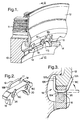
- a portion 10 of a turbine rotor disc of a gas turbine engine the outer periphery of which is formed with a series of fir tree formations 11 by means of which turbine blades are engaged with the periphery of the disc.
- the blades are retained against axial movement by an annular seal plate 12 held in engagement with the disc 10 by means of a series of radially directed projections 13 on the plate 12 engaged with lugs 14 on the rotor disc 10.
- the projections 13 and lugs 14 are spaced apart around the circumference of the seal plate and disc such that during assembly the projections 13 may pass through the gaps 15 between adjacent lugs 14, the seal plate then being rotated relative to the disc to engage the projections 13 with the adjacent lugs 14 as shown in Fig. 1.
- the seal plate is then locked against axial movement relative to the rotor disc until released by effecting relative rotation in one or other direction to bring the projections 13 into alignment with the recesses 15 which enables the seal plate to be removed.
- a locking device is provided to prevent relative rotational movement between them.
- the locking device comprises a body member 16 and a wire retaining member 17 best seen in Fig. 2 of the drawings.
- the body member 16 is shaped and dimensioned to form a close fit within a selected one of the gaps 15 between adjacent pairs of interengaged projections 13 and lugs 14, whereby to secure same against relative rotation.
- the body member is retained in position in the gap 15 by the retaining member 17 which is formed by bending from a single piece of wire of circular cross-section to form a pair of side-by-side hook-like formations 18 interconnected by a central linking portion 19.
- Each hook-like formation 18 comprises a central portion 18A which passes through a circular aperture 20 in the body member 16, and inner and outer portions or members 18B and 18C.
- the inner and outer members 18B, 18C project radially outwardly beyond the body member 16 and abut against adjacent surfaces 12A and 12B of the seal plate 12.
- the distance between the hook-like formations 18 is slightly greater or less than the spacing between the apertures 20 whereby to place the retaining member under tension or compression.
- the wire is preferably formed from a cobalt/chrome alloy selected for high temperature capabilities and high frettage resistance. In a typical application the wire may be of the order of 1.0 to 1.5mm and preferably 1.2mm in diameter.
- the retaining member is subjected to centrifugal force in a radially outward direction. This forces the retaining member upwards as shown in the drawings and causes plastic deformation of the wire, thus forcing the retaining member more tightly into contact with the adjacent surfaces of the seal plate. This causes intimate contact between the wire and seal plate thereby minimising relative movement between them.
- the opposite ends of the apertures 20 are contoured to maximise surface contact with the retaining member. Thus as best seen in Fig. 3, the opposite ends of the apertures are of gradually increasing diameter to blend with the curvature of the hook-like formations 18.
- the seal plate is engaged with the rotor disc and rotated to bring the projections 13 into engagement with the lugs 14.
- the locking device is then located in an appropriate one of the gaps 15 between two of the lugs 14 with the formations 18 partly formed so that the free ends 18C projecting axially from the associated apertures 20 as indicated by the broken lines in Fig. 3. Sections 18C are then deformed into the position shown in full lines in Fig. 3 in which they abut the contoured surface 12A of the side plate.
- the retaining member thus retains the body member 16, and hence the locking device as a whole, in position in the gap 15 in which it prevents relative rotational movement between the seal plate and the rotor disc.
- any desired number of locking devices may be located in the gaps 15 between adjacent lugs 14 on the rotor disc.
- a pair of locking devices will be fitted at radially opposite locations in order to minimise additional weight, but a single locking device or more than two such devices could be employed if desired.
- the locking device described has a number of benefits compared with previously proposed locking devices for this purpose.
- the use of wire retaining members engageable with the body member through apertures of circular cross-section simplifies manufacture compared with previous arrangements and thereby results in cost saving.
- the use of wire retaining members also produces a reduction in weight.
- the close fitting nature of the retaining member both with the body member of the locking device and with the adjacent surfaces of the seal plate produces a reduction in movement, stress and wear during use.
Landscapes
- Engineering & Computer Science (AREA)
- Mechanical Engineering (AREA)
- General Engineering & Computer Science (AREA)
- Turbine Rotor Nozzle Sealing (AREA)
- Snaps, Bayonet Connections, Set Pins, And Snap Rings (AREA)
- Lock And Its Accessories (AREA)
- Clamps And Clips (AREA)
Abstract
Description
Claims (9)
- A locking device for use in retaining rotationally interengaged components (10,12) in engagement with one another, the device comprising a body member (16) adapted to be located between adjacent interengaging formations (13,14) on the components (10,12) in a manner to prevent relative rotation of the components (10,12), and a retaining member (17) adapted to locate the body member (16) in position characterised in that, the retaining member (17) is formed from wire and comprises at least two hook-like members (18) engaged in spaced apertures (20) in said body member (16), each hook-like member (18) having first and second portions (18B,18C) thereof extending beyond said body member (16) into engagement with inner and outer surfaces (12B,12A) of one of said components (10,12).
- A locking device according to claim 1 characterised in that the components comprise a rotor disc (10) and seal plate (12) of a turbine assembly, said portions (18B,18C) of said retaining member (17) extending radially outwardly of said body member (16) into engagement with adjacent inner (12B) and outer (12A) surfaces of said seal plate (12).
- A locking device for retaining a rotationally interengaged seal plate (12) and rotor disc (10) of a gas turbine engine in engagement with one another, the device comprising a body member (16) shaped and dimensioned to form a close fit within a gap between adjacent interengaged lugs (14) and projections (13) on the seal plate (12) and rotor disc (10), and a retaining member (17) characterised in that the retaining member (17) is formed from wire and comprises at least two hook-like members (18) engaged in spaced apertures (20) in said body member (17), each hook-like member (18) having first and second portions (18B,18C) thereof extending beyond said body member (16) into engagement with inner and outer surfaces (12B,12A) of said seal plate (12).
- A locking device according to any preceding claim characterised in that the spacing between said hook-like members (18) differs slightly from the spacing between said apertures (20) in the body member (16), whereby the retaining member (17) is maintained under tension or compression.
- A locking device according to any preceding claim characterised in that said retaining member (17) is formed by bending from a single length of wire.
- A locking device according to any preceding claim characterised in that said wire (17) and said apertures (20) are of circular cross-section and of substantially the same diameter, whereby the hook-like members (18) are a close fit in the associated apertures (20).
- A locking device according to claim 6 characterised in that the opposite ends of the apertures (20) in said body member (16) are of outwardly increasing cross-section.
- A turbine rotor assembly for a gas turbine engine incorporating a locking device according to any preceding claim.
- A turbine rotor assembly for a gas turbine engine comprising a rotor disc (10) having a plurality of blades secured at the periphery thereof, an annular seal plate (12) engageable with said disc (10) to retain said blades against axial movement relative to the disc (10), means for releasably securing the seal plate (12) to the disc (10) in abutting relationship, said means including circumferentially spaced cooperating formations in the form of projections (13) and recesses (15) on the seal plate (12) and the disc (10) adapted for axial engagement and relative circumferential movement to secure the seal plate (12) to the disc (10), and a locking device to lock the seal plate (12) and disc (10) against relative rotational movement, the locking device comprising a body member (16) engageable in a gap (15) between adjacent interengaged formations (13,14) and a retaining member (17) characterised in that the retaining member (17) is formed by bending from a single length of wire to form a pair of side-by-side hook-like members (18) each adapted to pass through an associated aperture (20) in said body member (16) and having inner and outer portions thereof extending beyond said body member (16) into engagement with inner (12B) and outer (12A) surfaces of said seal plate (12) to retain the body member (16) in position in said gap (15).
Applications Claiming Priority (2)
| Application Number | Priority Date | Filing Date | Title |
|---|---|---|---|
| GB9925261 | 1999-10-27 | ||
| GBGB9925261.1A GB9925261D0 (en) | 1999-10-27 | 1999-10-27 | Locking devices |
Publications (3)
| Publication Number | Publication Date |
|---|---|
| EP1096107A2 true EP1096107A2 (en) | 2001-05-02 |
| EP1096107A3 EP1096107A3 (en) | 2004-05-12 |
| EP1096107B1 EP1096107B1 (en) | 2008-07-09 |
Family
ID=10863361
Family Applications (1)
| Application Number | Title | Priority Date | Filing Date |
|---|---|---|---|
| EP00309087A Expired - Lifetime EP1096107B1 (en) | 1999-10-27 | 2000-10-16 | Locking devices |
Country Status (4)
| Country | Link |
|---|---|
| US (1) | US6494684B1 (en) |
| EP (1) | EP1096107B1 (en) |
| DE (1) | DE60039397D1 (en) |
| GB (1) | GB9925261D0 (en) |
Cited By (18)
| Publication number | Priority date | Publication date | Assignee | Title |
|---|---|---|---|---|
| EP1584794A1 (en) * | 2004-04-09 | 2005-10-12 | Snecma | Axial retention device for the blades in a disk of a turbomachine rotor |
| EP1607579A1 (en) * | 2004-06-18 | 2005-12-21 | ROLLS-ROYCE plc | Locking means for gas turbine engines |
| EP1746250A1 (en) * | 2005-07-21 | 2007-01-24 | Snecma | Vibration damping elements for an axial holding ring of turbomachine fan blades |
| US7229252B2 (en) | 2004-10-21 | 2007-06-12 | Rolls-Royce Plc | Rotor assembly retaining apparatus |
| WO2007105701A1 (en) * | 2006-03-13 | 2007-09-20 | Ihi Corporation | Holding structure of fan blade |
| EP1849962A1 (en) * | 2006-04-27 | 2007-10-31 | Snecma | Retention system for blades on a rotor |
| EP1956194A1 (en) * | 2007-02-06 | 2008-08-13 | Siemens Aktiengesellschaft | Turbine assembly comprising a securing member and process of securing a side plate |
| EP2011969A1 (en) * | 2007-07-03 | 2009-01-07 | Siemens Aktiengesellschaft | Turbine assembly and method of fixing a mounting element |
| WO2011092439A1 (en) * | 2010-01-29 | 2011-08-04 | Snecma | Means for locking a sealing ring on a turbine wheel |
| RU2451215C2 (en) * | 2007-03-21 | 2012-05-20 | Снекма | Rotary assembly of gas turbine fan, gas turbine engine, fan with said assembly and gas turbine engine |
| RU2454572C2 (en) * | 2007-01-18 | 2012-06-27 | Снекма | Gas turbine engine fan rotor disk and gas turbine engine |
| WO2012136917A1 (en) * | 2011-04-05 | 2012-10-11 | Snecma | Sealing ring for a turbine stage of an aircraft turbomachine, comprising slotted anti-rotation pegs |
| RU2467211C2 (en) * | 2007-02-28 | 2012-11-20 | Снекма | Gas turbine engine fan, gas turbine engine and blade foot attachment flange bush |
| EP2224098A3 (en) * | 2009-02-25 | 2014-01-01 | General Electric Company | Apparatus for bucket cover plate retention |
| CN103930652A (en) * | 2011-11-15 | 2014-07-16 | 斯奈克玛 | Impeller for a turbomachine |
| EP2503098A3 (en) * | 2011-03-21 | 2015-02-25 | United Technologies Corporation | Rotor disk assembly and lock assembly therefor |
| CN106939800A (en) * | 2015-12-07 | 2017-07-11 | 通用电气公司 | Steam turbine rotor sealing key member, associated component and steamturbine |
| CN107013259A (en) * | 2015-12-07 | 2017-08-04 | 通用电气公司 | Steam turbine rotor sealing key member, associated component and steamturbine |
Families Citing this family (13)
| Publication number | Priority date | Publication date | Assignee | Title |
|---|---|---|---|---|
| FR2873161B1 (en) * | 2004-07-15 | 2008-10-10 | Snecma Moteurs Sa | ASSEMBLY COMPRISING A ROTARY SHAFT AND A BEARING BEARING |
| CN101258305B (en) * | 2005-09-07 | 2011-06-15 | 西门子公司 | Device for axially securing moving blades in a rotor, seal for such a device and use of such a device |
| US8215915B2 (en) * | 2009-05-15 | 2012-07-10 | Siemens Energy, Inc. | Blade closing key system for a turbine engine |
| FR2981132B1 (en) * | 2011-10-10 | 2013-12-06 | Snecma | DISCHARGE COOLING TURBOMACHINE ASSEMBLY |
| RU2517462C1 (en) * | 2013-03-01 | 2014-05-27 | Открытое акционерное общество "Авиадвигатель" | Turbine rotor |
| US20150078907A1 (en) * | 2013-09-13 | 2015-03-19 | General Electric Company | Turbomachine including a non-destructive fastener element for joining components |
| KR102182102B1 (en) * | 2014-11-27 | 2020-11-23 | 한화에어로스페이스 주식회사 | A turbine apparatus |
| DE102015116935A1 (en) * | 2015-10-06 | 2017-04-06 | Rolls-Royce Deutschland Ltd & Co Kg | Safety device for axially securing a blade and rotor device with such a securing device |
| GB2547906B (en) * | 2016-03-02 | 2019-07-03 | Rolls Royce Plc | A bladed rotor arrangement |
| US10385874B2 (en) | 2017-05-08 | 2019-08-20 | Solar Turbines Incorporated | Pin to reduce relative rotational movement of disk and spacer of turbine engine |
| EP3521561A1 (en) * | 2018-02-02 | 2019-08-07 | Siemens Aktiengesellschaft | Rotor with sealing element and sealing ring |
| US11021974B2 (en) | 2018-10-10 | 2021-06-01 | Rolls-Royce North American Technologies Inc. | Turbine wheel assembly with retainer rings for ceramic matrix composite material blades |
| US12055058B2 (en) * | 2022-05-31 | 2024-08-06 | Pratt & Whitney Canada Corp. | Joint between gas turbine engine components with a spring element |
Family Cites Families (18)
| Publication number | Priority date | Publication date | Assignee | Title |
|---|---|---|---|---|
| US1913555A (en) * | 1932-06-29 | 1933-06-13 | William S Lyle | Cotter pin |
| US2786648A (en) * | 1950-04-04 | 1957-03-26 | United Aircraft Corp | Blade locking device |
| US2697621A (en) * | 1950-06-21 | 1954-12-21 | Fafnir Bearing Co | Ring locking means |
| GB802476A (en) * | 1955-09-29 | 1958-10-08 | Rolls Royce | Improvements in or relating to rotors of axial-flow fluid machines for example compressors and turbines |
| GB928349A (en) * | 1960-12-06 | 1963-06-12 | Rolls Royce | Improvements in or relating to bladed rotors of fluid flow machines |
| US3341174A (en) | 1967-02-27 | 1967-09-12 | United Aircraft Corp | Blade lock |
| US3841794A (en) * | 1974-03-06 | 1974-10-15 | United Aircraft Corp | Snap-on lock for turbomachinery blades |
| FR2419389A1 (en) * | 1978-03-08 | 1979-10-05 | Snecma | IMPROVEMENTS TO TURBOMACHINE ROTOR FLANGES |
| US4232978A (en) | 1978-08-03 | 1980-11-11 | Grumman Aerospace Corporation | Double locking device |
| JPS5672298A (en) * | 1979-11-19 | 1981-06-16 | Hitachi Ltd | Fixing structure of rotary blade |
| US4389161A (en) * | 1980-12-19 | 1983-06-21 | United Technologies Corporation | Locking of rotor blades on a rotor disk |
| DE3220627A1 (en) * | 1982-06-01 | 1983-12-01 | Alno-Möbelwerke GmbH & Co KG, 7798 Pfullendorf | Connector for wooden parts |
| US4669959A (en) | 1984-07-23 | 1987-06-02 | United Technologies Corporation | Breach lock anti-rotation key |
| DE3836321A1 (en) | 1988-10-25 | 1990-04-26 | Wagener Gmbh Fritz | Display base for an article |
| US4846628A (en) * | 1988-12-23 | 1989-07-11 | United Technologies Corporation | Rotor assembly for a turbomachine |
| US5490662A (en) | 1995-03-29 | 1996-02-13 | Wright; Michael A. | Garage-door spring reinforcement and repair kit |
| GB2332024B (en) * | 1997-12-03 | 2000-12-13 | Rolls Royce Plc | Rotary assembly |
| DE19960896A1 (en) * | 1999-12-17 | 2001-06-28 | Rolls Royce Deutschland | Retaining device for rotor blades of axial turbine engine, with recesses in outer circumference of retainer corresponding to sections of blade receivers |
-
1999
- 1999-10-27 GB GBGB9925261.1A patent/GB9925261D0/en not_active Ceased
-
2000
- 2000-10-16 EP EP00309087A patent/EP1096107B1/en not_active Expired - Lifetime
- 2000-10-16 DE DE60039397T patent/DE60039397D1/en not_active Expired - Lifetime
- 2000-10-25 US US09/695,281 patent/US6494684B1/en not_active Expired - Fee Related
Non-Patent Citations (1)
| Title |
|---|
| None |
Cited By (39)
| Publication number | Priority date | Publication date | Assignee | Title |
|---|---|---|---|---|
| FR2868808A1 (en) * | 2004-04-09 | 2005-10-14 | Snecma Moteurs Sa | DEVICE FOR THE AXIAL RETENTION OF AUBES ON A ROTOR DISC OF A TURBOMACHINE |
| RU2358116C2 (en) * | 2004-04-09 | 2009-06-10 | Снекма | Device for blades fixing to turbo machine rotor disc in axial direction |
| EP1584794A1 (en) * | 2004-04-09 | 2005-10-12 | Snecma | Axial retention device for the blades in a disk of a turbomachine rotor |
| US7371050B2 (en) | 2004-04-09 | 2008-05-13 | Snecma | Device for axially retaining blades on a turbomachine rotor disk |
| US7318704B2 (en) | 2004-06-18 | 2008-01-15 | Rolls-Royce Plc | Gas turbine engine structure |
| EP1607579A1 (en) * | 2004-06-18 | 2005-12-21 | ROLLS-ROYCE plc | Locking means for gas turbine engines |
| US7229252B2 (en) | 2004-10-21 | 2007-06-12 | Rolls-Royce Plc | Rotor assembly retaining apparatus |
| US7458769B2 (en) | 2005-07-21 | 2008-12-02 | Snecma | Device for damping vibration of a ring for axially retaining turbomachine fan blades |
| FR2888897A1 (en) * | 2005-07-21 | 2007-01-26 | Snecma | DEVICE FOR DAMPING THE VIBRATION OF AN AXIAL RETAINING RING OF BLOWER BLADES OF A TURBOMACHINE |
| EP1746250A1 (en) * | 2005-07-21 | 2007-01-24 | Snecma | Vibration damping elements for an axial holding ring of turbomachine fan blades |
| CN1900533B (en) * | 2005-07-21 | 2011-09-07 | 斯奈克玛 | Vibration damping elements for an axial holding ring of turbomachine fan blades |
| WO2007105701A1 (en) * | 2006-03-13 | 2007-09-20 | Ihi Corporation | Holding structure of fan blade |
| FR2900437A1 (en) * | 2006-04-27 | 2007-11-02 | Snecma Sa | SYSTEM FOR RETENTING AUBES IN A ROTOR |
| EP1849962A1 (en) * | 2006-04-27 | 2007-10-31 | Snecma | Retention system for blades on a rotor |
| US7824157B2 (en) | 2006-04-27 | 2010-11-02 | Snecma | System for retaining blades in a rotor |
| RU2454572C2 (en) * | 2007-01-18 | 2012-06-27 | Снекма | Gas turbine engine fan rotor disk and gas turbine engine |
| EP1956194A1 (en) * | 2007-02-06 | 2008-08-13 | Siemens Aktiengesellschaft | Turbine assembly comprising a securing member and process of securing a side plate |
| RU2467211C2 (en) * | 2007-02-28 | 2012-11-20 | Снекма | Gas turbine engine fan, gas turbine engine and blade foot attachment flange bush |
| RU2451215C2 (en) * | 2007-03-21 | 2012-05-20 | Снекма | Rotary assembly of gas turbine fan, gas turbine engine, fan with said assembly and gas turbine engine |
| EP2011969A1 (en) * | 2007-07-03 | 2009-01-07 | Siemens Aktiengesellschaft | Turbine assembly and method of fixing a mounting element |
| EP2224098A3 (en) * | 2009-02-25 | 2014-01-01 | General Electric Company | Apparatus for bucket cover plate retention |
| CN102713161A (en) * | 2010-01-29 | 2012-10-03 | 斯奈克玛 | Means for locking a sealing ring on a turbine wheel |
| CN102713161B (en) * | 2010-01-29 | 2015-08-19 | 斯奈克玛 | Device for locking sealing rings on turbine discs |
| US9033666B2 (en) | 2010-01-29 | 2015-05-19 | Snecma | Means for locking a sealing ring on a turbine disk |
| JP2013518212A (en) * | 2010-01-29 | 2013-05-20 | スネクマ | Means for locking the seal ring to the turbine disk |
| WO2011092439A1 (en) * | 2010-01-29 | 2011-08-04 | Snecma | Means for locking a sealing ring on a turbine wheel |
| EP2503098A3 (en) * | 2011-03-21 | 2015-02-25 | United Technologies Corporation | Rotor disk assembly and lock assembly therefor |
| CN103459777B (en) * | 2011-04-05 | 2015-04-15 | 斯奈克玛 | Turbine stage seals for aircraft turbomachines, including slotted anti-rotation pins |
| CN103459777A (en) * | 2011-04-05 | 2013-12-18 | 斯奈克玛 | Sealing ring for a turbine stage of an aircraft turbomachine, comprising slotted anti-rotation pegs |
| FR2973829A1 (en) * | 2011-04-05 | 2012-10-12 | Snecma | SEALING PLATE FOR AIRCRAFT TURBINE TURBINE TURBINE, COMPRISING ANTI-ROTATING FENSE TENONS |
| WO2012136917A1 (en) * | 2011-04-05 | 2012-10-11 | Snecma | Sealing ring for a turbine stage of an aircraft turbomachine, comprising slotted anti-rotation pegs |
| RU2594392C2 (en) * | 2011-04-05 | 2016-08-20 | Снекма | Seal ring for turbine stage aircraft turbine machine containing shutoff projections with slots, rotor stage of turbomachine, turbomachine and method of making sealing ring |
| US9494042B2 (en) | 2011-04-05 | 2016-11-15 | Snecma | Sealing ring for a turbine stage of an aircraft turbomachine, comprising slotted anti-rotation pegs |
| CN103930652A (en) * | 2011-11-15 | 2014-07-16 | 斯奈克玛 | Impeller for a turbomachine |
| CN103930652B (en) * | 2011-11-15 | 2016-08-24 | 斯奈克玛 | A kind of rotor wheel for turbogenerator |
| CN106939800A (en) * | 2015-12-07 | 2017-07-11 | 通用电气公司 | Steam turbine rotor sealing key member, associated component and steamturbine |
| CN107013259A (en) * | 2015-12-07 | 2017-08-04 | 通用电气公司 | Steam turbine rotor sealing key member, associated component and steamturbine |
| CN107013259B (en) * | 2015-12-07 | 2020-12-08 | 通用电气公司 | Steam turbine rotor seal key parts, related components and steam turbines |
| CN106939800B (en) * | 2015-12-07 | 2021-05-04 | 通用电气公司 | Steam turbine rotor seal key parts, related components and steam turbines |
Also Published As
| Publication number | Publication date |
|---|---|
| EP1096107A3 (en) | 2004-05-12 |
| US6494684B1 (en) | 2002-12-17 |
| DE60039397D1 (en) | 2008-08-21 |
| EP1096107B1 (en) | 2008-07-09 |
| GB9925261D0 (en) | 1999-12-29 |
Similar Documents
| Publication | Publication Date | Title |
|---|---|---|
| US6494684B1 (en) | Locking devices | |
| US10215036B2 (en) | Blade attachment assembly | |
| US7059831B2 (en) | Turbine engine disk spacers | |
| US6315519B1 (en) | Turbine inner shroud and turbine assembly containing such inner shroud | |
| EP0374387B1 (en) | Locking of side-entry blades | |
| US7147436B2 (en) | Turbine engine rotor retainer | |
| US8814524B2 (en) | Wheel formed from a bladed ring and disk | |
| EP0421596B1 (en) | Labyrinth seal support | |
| EP1916389A1 (en) | Turbine blade assembly | |
| US11585241B2 (en) | Assembly for a turbomachine turbine and associated turbomachine | |
| KR20110126708A (en) | Rotor sections for rotors of turbomachines and rotor blades for turbomachines | |
| US20020081195A1 (en) | Bucket tip brush seals in steam tubines and methods of installation | |
| US8147200B2 (en) | Turbine engine wheel | |
| EP4428341B1 (en) | Retaining assembly with anti-rotation feature | |
| JP2000320497A (en) | Mutually fixed compressor stator | |
| JPH04342830A (en) | Shearing wire flange coupling | |
| EP2354457A2 (en) | Rotor disk and blade | |
| US20060291955A1 (en) | Assembly including a rotary shaft and a roller bearing | |
| US11591924B2 (en) | Assembly for a turbomachine turbine | |
| Garcia-Crespo et al. | Blade attachment assembly |
Legal Events
| Date | Code | Title | Description |
|---|---|---|---|
| PUAI | Public reference made under article 153(3) epc to a published international application that has entered the european phase |
Free format text: ORIGINAL CODE: 0009012 |
|
| AK | Designated contracting states |
Kind code of ref document: A2 Designated state(s): AT BE CH CY DE DK ES FI FR GB GR IE IT LI LU MC NL PT SE |
|
| AX | Request for extension of the european patent |
Free format text: AL;LT;LV;MK;RO;SI |
|
| PUAL | Search report despatched |
Free format text: ORIGINAL CODE: 0009013 |
|
| AK | Designated contracting states |
Kind code of ref document: A3 Designated state(s): AT BE CH CY DE DK ES FI FR GB GR IE IT LI LU MC NL PT SE |
|
| AX | Request for extension of the european patent |
Extension state: AL LT LV MK RO SI |
|
| 17P | Request for examination filed |
Effective date: 20040420 |
|
| AKX | Designation fees paid |
Designated state(s): DE FR GB |
|
| GRAP | Despatch of communication of intention to grant a patent |
Free format text: ORIGINAL CODE: EPIDOSNIGR1 |
|
| GRAS | Grant fee paid |
Free format text: ORIGINAL CODE: EPIDOSNIGR3 |
|
| GRAA | (expected) grant |
Free format text: ORIGINAL CODE: 0009210 |
|
| AK | Designated contracting states |
Kind code of ref document: B1 Designated state(s): DE FR GB |
|
| REG | Reference to a national code |
Ref country code: GB Ref legal event code: FG4D |
|
| REF | Corresponds to: |
Ref document number: 60039397 Country of ref document: DE Date of ref document: 20080821 Kind code of ref document: P |
|
| PLBE | No opposition filed within time limit |
Free format text: ORIGINAL CODE: 0009261 |
|
| STAA | Information on the status of an ep patent application or granted ep patent |
Free format text: STATUS: NO OPPOSITION FILED WITHIN TIME LIMIT |
|
| 26N | No opposition filed |
Effective date: 20090414 |
|
| PGFP | Annual fee paid to national office [announced via postgrant information from national office to epo] |
Ref country code: FR Payment date: 20101104 Year of fee payment: 11 |
|
| PGFP | Annual fee paid to national office [announced via postgrant information from national office to epo] |
Ref country code: DE Payment date: 20101022 Year of fee payment: 11 |
|
| PGFP | Annual fee paid to national office [announced via postgrant information from national office to epo] |
Ref country code: GB Payment date: 20101021 Year of fee payment: 11 |
|
| GBPC | Gb: european patent ceased through non-payment of renewal fee |
Effective date: 20111016 |
|
| REG | Reference to a national code |
Ref country code: FR Ref legal event code: ST Effective date: 20120629 |
|
| PG25 | Lapsed in a contracting state [announced via postgrant information from national office to epo] |
Ref country code: DE Free format text: LAPSE BECAUSE OF NON-PAYMENT OF DUE FEES Effective date: 20120501 |
|
| REG | Reference to a national code |
Ref country code: DE Ref legal event code: R119 Ref document number: 60039397 Country of ref document: DE Effective date: 20120501 |
|
| PG25 | Lapsed in a contracting state [announced via postgrant information from national office to epo] |
Ref country code: GB Free format text: LAPSE BECAUSE OF NON-PAYMENT OF DUE FEES Effective date: 20111016 Ref country code: FR Free format text: LAPSE BECAUSE OF NON-PAYMENT OF DUE FEES Effective date: 20111102 |