EP1096086B1 - Door lock, in particular for tractors - Google Patents
Door lock, in particular for tractors Download PDFInfo
- Publication number
- EP1096086B1 EP1096086B1 EP00122017A EP00122017A EP1096086B1 EP 1096086 B1 EP1096086 B1 EP 1096086B1 EP 00122017 A EP00122017 A EP 00122017A EP 00122017 A EP00122017 A EP 00122017A EP 1096086 B1 EP1096086 B1 EP 1096086B1
- Authority
- EP
- European Patent Office
- Prior art keywords
- door lock
- tube
- lock according
- lever
- rotary
- Prior art date
- Legal status (The legal status is an assumption and is not a legal conclusion. Google has not performed a legal analysis and makes no representation as to the accuracy of the status listed.)
- Expired - Lifetime
Links
Images


Classifications
-
- E—FIXED CONSTRUCTIONS
- E05—LOCKS; KEYS; WINDOW OR DOOR FITTINGS; SAFES
- E05B—LOCKS; ACCESSORIES THEREFOR; HANDCUFFS
- E05B85/00—Details of vehicle locks not provided for in groups E05B77/00 - E05B83/00
- E05B85/10—Handles
-
- E—FIXED CONSTRUCTIONS
- E05—LOCKS; KEYS; WINDOW OR DOOR FITTINGS; SAFES
- E05B—LOCKS; ACCESSORIES THEREFOR; HANDCUFFS
- E05B85/00—Details of vehicle locks not provided for in groups E05B77/00 - E05B83/00
- E05B85/20—Bolts or detents
- E05B85/24—Bolts rotating about an axis
- E05B85/247—Bolts rotating about an axis about a vertical axis
-
- Y—GENERAL TAGGING OF NEW TECHNOLOGICAL DEVELOPMENTS; GENERAL TAGGING OF CROSS-SECTIONAL TECHNOLOGIES SPANNING OVER SEVERAL SECTIONS OF THE IPC; TECHNICAL SUBJECTS COVERED BY FORMER USPC CROSS-REFERENCE ART COLLECTIONS [XRACs] AND DIGESTS
- Y10—TECHNICAL SUBJECTS COVERED BY FORMER USPC
- Y10S—TECHNICAL SUBJECTS COVERED BY FORMER USPC CROSS-REFERENCE ART COLLECTIONS [XRACs] AND DIGESTS
- Y10S292/00—Closure fasteners
- Y10S292/23—Vehicle door latches
-
- Y—GENERAL TAGGING OF NEW TECHNOLOGICAL DEVELOPMENTS; GENERAL TAGGING OF CROSS-SECTIONAL TECHNOLOGIES SPANNING OVER SEVERAL SECTIONS OF THE IPC; TECHNICAL SUBJECTS COVERED BY FORMER USPC CROSS-REFERENCE ART COLLECTIONS [XRACs] AND DIGESTS
- Y10—TECHNICAL SUBJECTS COVERED BY FORMER USPC
- Y10T—TECHNICAL SUBJECTS COVERED BY FORMER US CLASSIFICATION
- Y10T292/00—Closure fasteners
- Y10T292/08—Bolts
- Y10T292/0862—Swinging and hooked end, multiple head
-
- Y—GENERAL TAGGING OF NEW TECHNOLOGICAL DEVELOPMENTS; GENERAL TAGGING OF CROSS-SECTIONAL TECHNOLOGIES SPANNING OVER SEVERAL SECTIONS OF THE IPC; TECHNICAL SUBJECTS COVERED BY FORMER USPC CROSS-REFERENCE ART COLLECTIONS [XRACs] AND DIGESTS
- Y10—TECHNICAL SUBJECTS COVERED BY FORMER USPC
- Y10T—TECHNICAL SUBJECTS COVERED BY FORMER US CLASSIFICATION
- Y10T292/00—Closure fasteners
- Y10T292/08—Bolts
- Y10T292/1043—Swinging
- Y10T292/1044—Multiple head
- Y10T292/1045—Operating means
- Y10T292/1047—Closure
Definitions
- the invention relates to a door lock according to the preamble of claim 1.
- a door lock according to the preamble of claim 1.
- Such a lock is disclosed in EP-A1-0 849 424 described.
- the rotary latch lock has a pair of counter-rotating, rotatably mounted rotary latch members on which a locking bolt in the catch by means of a Hold the locking lever of the near-actuated release device.
- a Lock lever actuator When pressing or releasing the locking lever by a Lock lever actuators pivot the rotary latch members from each other directed away into a detent unlocked position, which allows the vehicle door to be opened can.
- the locking lever is included aligned so pivotally that he after releasing the locking lever actuator into engagement with the rotary latch members is returned.
- Each of the rotary latch members has a toothing its rotary latch back outer surface provided which is positioned so that it is in a cam surface engage the arm of the locking lever counter-locking and the latter lead into such a rotary latch member position that they are not adjustable in the case of a normal position.
- Another motor vehicle door lock is from the document DE-OS 30 10 388 known that with a on a base plate arranged and in a snapped and a not snapped Position movable Schnapporgan of two rotary latch members is provided, with which a pawl cooperates, which a latch bolt in the snapped Holds position and this when moving to move into unlocked position releases and which via a Operating lever is actuated. Between the operating lever and the base plate is a pin / slot connection provided such that the actuating lever between a Normal and one operating position movable and as a whole between a coupling and a decoupling position is displaceable relative to the pawl.
- the operating lever is in the coupling position with the pawl in engagement can be brought and moved such that the locking pin is released when the operating lever, the coupling position occupies and from the normal to the operating position is brought.
- the operating lever is opposite the pawl idle when it is in the decoupling position and moved from the normal to the operating position, without the pawl to release the locking pin to press.
- a locking lever is provided, which between a latch and unlock position is movable and over a connecting element with the actuating lever in connection which consists of a projection on a lever and a receiving this slot in the second lever.
- the projection interacts with the edges of the slot, that when moving the locking lever of the Entriegelin the locking position of the operating lever as a whole of the coupling is moved to the decoupling position.
- Of the Slot is designed so that in the coupling or Decoupling position and from the normal to the Operating position moving actuating lever of the projection is movable in the slot.
- a generic vehicle door lock is in the document EP 0 849 424 A1, which is a rotary latch lock for locking closing a door, in particular representing a vehicle door of a tractor.
- the catch from two rotary latch links stands with a rotary latch spring and a locking piece in cooperation, wherein the catch and the locking piece are pivotable and - the castle locking - can interact.
- the lock can by a lever system having an operating lever and acts on the locking piece to be solved.
- the locking piece is mounted on a pivotable about a first axis Locking arm of the lever system actuated, the operative connection with an opening lever, which is about a second axis is pivotable.
- the first and second axes are parallel aligned with each other, wherein a connecting means, which in each case a free end of the latching arm and the actuating lever brings into operative connection, is arranged. there are the locking arm and the operating lever to their pivot axes swiveled in the same direction.
- the well-known door locks can be with a pusher or operate lever from the outside of the door and with a second one Operate lever from the vehicle interior, usually from a vehicle exterior, a near trigger, i. an immediate one operated on the lock trigger mechanism actuated is and the operation of the vehicle inside a Remote triggering is, i. for example the operation of the lock on a steel wire or a Tiller crossbar.
- the invention is based on the object, a door lock, especially for agricultural vehicles, which is designed such that the remote control, especially from the vehicle interior, easy to different Door types and shapes adaptable and fast to be mounted on a door, the mechanism being particularly robust with regard to vibration loads with simple Mountability is.
- the mechanism is designed so that the pipe is also an angled can have a bent course without the reliability to negatively influence the mechanics.
- the operating lever the remote release in the tube longitudinally displaceable stored.
- the lock case presents a trough-like or box-shaped Container that as coherent wall parts a trough bottom, a first short side lock wall, a second opposite short side lock wall as well as one first long side lock wall, wherein the second Long side lock wall divided into two parts from a first lock wall part and a second lock wall part, being approximately centrally between the two Sch gutwandungsutz the box opening is through which the locking bolt in the lock box in and out of the lock box movable is.
- the two interconnected lever arms of the pawl lever are a vertical lever arm and a horizontal one Lever arm with an associated angle range, with the vertical Lever preferably end Schemes rock the locking piece owns and directed approximately parallel to the Lang incidentschingtonwandung is and where the horizontal lever arm is approximately parallel the Kurztimeschndung is directed and extends into the corner of the Sch thoroughlywandept next to the upper rotary latch member extends.
- the horizontal lever arm of the pawl lever stands with the remotely actuated, preferably internally actuable release device and their remote release lever in conjunction.
- the rotary latch associated with the vertical lever arm of the pawl lever stands with the handle-actuated release device and their proximity trigger in conjunction.
- the remote release lever and the proximity release lever are independent each other assigned to the pawl lever, wherein the Remote release lever via one end-side engagement element with the horizontal lever arm and the proximity release lever communicate with the vertically directed lever arm.
- the pawl lever is spring-assisted, the pressure the spring is directed in the direction of the rotary latch.
- the door handle actuable release device is equipped with a swiveling door handle, which is stored in a door handle recess is provided with the door handle with a door handle recess attached lever device and an attached thereto Platform is connected across the door handle recess, whereby by the movement of the platform of Nahauslbücherhebel is pivotable.
- the innenfig button-actuable release device consists outside the lock case from a preferably step-like Pipe bracket angle part, from an attached, pivotable Traverse tube, which is directed to the lock case is open and with a door adapted to the free other end mountable, with a slot provided pipe crimping is provided, as well as one on and in the truss pipe located sensing device, from the one with a Rope hook end reinforced pull rope to the with the pipe bracket angle part related, perforated and rope hooks receptive Remote release lever is guided.
- the tube holding angle part consists of the preferably edge side vertically molded or attached to the lower lid part Angle section, from a part of the lid lockbox laterally staggered Actuallyndistanzteil and off a pipe holding part, on which the truss pipe on the one hand attached at the end, preferably screwed.
- the tube holding angle part represents a material and form minimalized Holding and spacer element.
- the first short side lock wall has a preferably rectangular free cut opening in the corner between the first Long side lock wall and the lid part on.
- the lid is divided into two parts in a lower first lid part and an upper second lid part, wherein at the lower first cover part at a right angle to the outside angled, outstanding rotary-hole attachment is present, on which the Nahausl Harborhebel pivotally mounted bolted and the pipe bracket angle part are formed on the truss pipe is attached.
- Both the rotary hole header and the pipe bracket angle part are at right angles to each other preferably on a Dekkelteil arranged.
- the pull rope or the rod is pivotable about the axis about the mounted remote release lever and the engagement extension associated with the lock box feature interior.
- the remote release lever is by means of the pivot bearing screw attached to the pipe bracket portion, wherein in the lock box, especially in the lower cover part in the area of the remote release lever a window is provided so that over the am Remote release lever molded engagement extension of the Lock case pivoting pawl lever operable is.
- the truss pipe is preferably associated with, at the free Pipe end befindaji pipe crushing on the pipe holding part of the pipe bracket part over the pipe support block and the screw fastened adjustable.
- the two release levers can with the pawl lever, especially with its lever arms over more different recessed and inserted corresponding locking elements keep in touch.
- the traverse tube of the button-actuable triggering device is at the tube holding part of the step-like tube holding angle part pivotally mounted, in particular screwed.
- the pull rope or the rod is up to Guided sensing device, preferably centrally on the truss tube and vertically up out of the cut Tube is arranged.
- the remote release lever is one provided with a mounting hole Seilauf 1967 molded, wherein the mounting hole the Reinforced rope hooks opposite the pull rope or the rod retaining and the Seilauf mecanic and the engaging extension are preferably directed in parallel.
- the truss tube preferably has at the Rohroberseite longitudinally a longitudinal slot opening and a locking tube longitudinal opening on, in which the sensing device with the Push button is mounted longitudinally displaceable.
- the pushbutton is equipped with a push-button holding body located in the tube connected, which from one of the locking tube longitudinal opening in the crossbar area associated sprag part and from a the cartridge body associated probe holding body part consists.
- the sprag part is preferably the same or narrower as the width of the longitudinal slot opening for easy installation the sensing device formed in the truss tube.
- the sprag part is in the transition region of the locking tube longitudinal opening for longitudinal slot opening with each a left-side stop transverse edge and a right-side Provide transverse stop edge, which is directed transversely to the pipe run are and in each case to the Tastangeschteil run, in the tube longitudinal direction just above the holding body support ends, with the Tast analyses interviewer with their continuing edge areas at the transverse stop edges abut the sprag part so that the button in his Normal position is held in a predetermined position.
- FIGS. 1, 1a will be considered together.
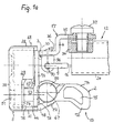
- Fig. 1 is essentially the door lock 1 according to the invention with a nahbetätigbaren tripping device 13 and with a remotely actuable trip device 12.
- the near-actuated release device 13 provides a from outside the door preferably door handle actuable release device dar.
- the remote-controlled release device Fig. 12 illustrates a preferably intra-button actuatable button Tripping device.
- the door handle actuatable release device shown in Fig. 1 13 has outside the lock case 5 a manual actuatable hinged door handle 18, which in a door handle recess 15 is stored, on, wherein the door handle 18 with an attached to the door handle recess 15 lever means 19 and an attached platform 26 transverse to Door handle recess 18 is connected, whereby by the movement of the Platform 26 of Nahausletteshebel 2 about the axis 67 pivotally is stored.
- the proximity release lever 2 as shown in Fig. 1a, is within of the lock case 5 with one from the plane of the drawing protruding locking pin 25 in conjunction, the at Swiveling the Nahausletteshebels 2 also pivoted is, wherein the locking pin 25 by a compression spring (not marked) is supported. Furthermore, the Nah has release lever 2 located outside the lock case 5 Support projection 48, the end in normal position 5 rests on the lock case.
- the Nahauslettehebel 2 is at the free end of the outside Lock box 5, brought closer to the platform 26 to be with a projection 72 having, and as shown in Fig. 3, with one of the button-actuated Tripping device 12 tilted away, slightly twisted head 74 provided, the head 74 by a continuous Head recess 75 material saving and u.a. easier to use is.
- the innenfig button-actuable release device 12 is outside the lock case 5 from a preferably single-stage tube bracket part 17, from an attached, pivotable truss tube 24, the lock box 5 is open and open at the other end door-mounted mountable, provided with a slot 39 Pipe crimping 31 has, wherein the crossbar 24th via a bent to the outer trough bent Pipe taper 56 merges into the tube pinch 31.
- the remotely operated triggering device contains 12 a located on and in the crossbar 24 sensing device 11, from which one end-reinforced with a cable hook 9 Pulling cable 16 to a with the pipe bracket angle part 17 in Connecting and cable hook receiving remote release lever 3 is guided.
- the preferably metallic lock case 5 in Figs. 1,1a has the shape of a laterally closed trough whose Wall parts preferably from a ganz Foundation cut free Base appropriately bent at right angles are, where in the hollow the essential functional interior the door lock 1 is included.
- the lock case 5 has a Tray bottom 38, a first short side lock wall 29 and a second opposite short side lock wall 44 and a first long side lock wall 30, wherein the second Long side lock wall divided into two parts from a first Lock wall part 28 and a second lock wall part 68 exists.
- the lid is in two parts in a lower one first cover part 78 and an upper second cover part 79 designed, wherein the lower first cover part 78 a to a right angle outward angled, more prominent Drehlochvorsatz 52 is present, where the Nahausl Harborhebel 2 is pivotally mounted screwed, and a pipe bracket angle part 17 is integrally formed, on which the truss tube 24 is attached is. Both the rotary hole attachment 52 and the tube holding angle part 17 are arranged at right angles to each other.
- the first short side lock wall 29 has a preferably rectangular cutout opening 76 in the corner between the first Long side lock wall 30 and the lid part 79 on.
- Fig. 1a the upper lid part 79 by means of the screw 51 on the trough bottom 38 and by means of the intermediately stored Distance sleeves 53,54 attached.
- the pipe bracket part 17 is connected to the lower lid part 78, integrally formed or screwed, also by means of two screw connections (Not shown in Fig. 1,1a) on the trough bottom 38th is firmly held.
- Fig. 1 is shown in plan view. Of the Lock case 5 has the well bottom 38, the lock wall parts 28 and 68 and the Kurzchemistryschitz Wegneckonne 29,44 on. Between the Sch towandungs kind 28.68 is the box opening 14 present for the movement of the rotary latch members 7.8 over the level of Sch towandungsmaschine 28.68 is provided out.
- the lower lid part 78 is not just a holding part for the Nahausletteshebel 2, but also for the remote release lever 3, which is pivotable on at the lower lid part 78th molded tubular bracket portion 17 stored and supported is.
- the pull cable 16 is rotatably mounted about the axis 33 about the Fernausletteshebel 3 and its engaging projection 45 with connected to the functional interior of the lock case 5.
- Fig. 3 is a side view of the side of the two Tripping devices 12,13 shown in FIG. 1.
- Lock case 5 is upright as installed in the door shown.
- the trough bottom 38 has the box opening 14, in which the locking pin 6 engages when the Door is closed.
- the box opening 14 of the remains Lock pin 6 as long as the rotary latch members 7.8 (not shown) embrace him holding.
- the upper cover part 79 is through the screw / Drehhalterungsschrauben 51 as well as 40 including the between trough bottom 38 and cover part 79 arranged spacers edge-leveled into the lock walls 30, 29, 28 fitted while the lower lid portion 78 between the Sch thoroughlywandungen 30,68 leveled fitted and on the Kurztownschrawdung 44 rests. Also the second lower one Cover part 78 is of two by lock-internal spacers 94.95 supported screw connections / swivel mounting screws 43.93 held.
- the remote release lever 3 is by means of the rotary bearing screw 47 on the pipe bracket angle part 17 and pivotable about the axis 33 attached.
- the lock case 5 especially in the lower Cover part 78 is in the region of the remote release lever. 3 a preferably rectangular window 55 is provided so that via the integrally formed on the remote release lever 3 engagement extension 45 located in the lock case 5 pawl lever 27th is operable.
- the Nahauslettehebel 2 associated support projection 48 is located in the load-free case (normal position) preferably the edge of the long side lock wall 30.
- the proximity trigger 2 may contain a slot slot in the middle, with he is displaced to the platform 26 and by means of Drehlagerungsschraube 50 can be locked.
- the crossbar tube 24 with associated pipe crimping 31st is at the pipe bracket angle part 17 via the pipe support block 34 and the screw 37 adjustable adjustable.
- FIGS. 4, 5 are considered together in the following, wherein the door lock 1 according to the invention specified in the edgewise Can be used in left-side doors of vehicles is. The same applies to right-hand doors.
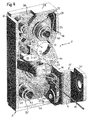
- Fig. 4 is in a perspective view and in open State largely the functional interior of the lock box 5 of the door lock 1 according to the invention shown.
- the door lock 1 includes a box opening 14, there receive a locking pin 6 of the vehicle Lock case 5 and the door handle operable Nahausletteshebel 2, wherein in the lock case 5 a supported by a spring 77 Rotary latch 10 for the Umgriff of the box opening 14th Passed locking bolt 6 and a twisting positions the two rotary latch members 7,8 fixing, flat trained Pawl lever 27 for a Dreh fallengliederhalternden Detent engagement in the rotary latch 10 facing away Latch latch gears 61 (61 is a reference numeral representative of the limb locking teeth of the two Rotary latch members 7,8 is) are present.
- the flat pawl lever 27 has two approximately at right angles to each other Lever arms 63,64 and is in the associated corner-related Angular range 65 by means of a Drehhalterungsbolzens 43, which has a spacer sleeve 95, pivotally mounted. Furthermore, the pawl lever 27 has a vertical lever arm 63 end-associated locking piece 66th on, the counter-locking teeth 62 the limb locking gears 61 opposite and at locking pin Umgriffpositionen the rotary latch members 7,8, the rotary latch 10 upright holding, engages the limb locking gears 61.
- the Link locking teeth 61 have at least three teeth, on whose rotary latch back outer peripheral surface 71 the Gegenrastveriereung 62 of the locking piece 66 abut or engage can. In Fig. 4, the counter-locking tooth 62 engages in the limb locking teeth 61 a.
- the pawl lever 27 is the second, via a Traverse tube 24 guided and arranged, push-button actuated Tripping device 12 in such a way that of lock box outside with each of the two tripping devices 13 and 12 about their respective Nah- or Remote release lever 2 or 3 of the locking pin 6 from the catch 10 is solvable.
- the rotary latch 10 consists of two rotary latch members - a upper rotary latch member 7 and a lower rotary latch member. 8 -, Which have mutually facing grooves 32,73 and at the opposite rotary latch back outer Peripheral surfaces 71 have limb locking teeth 61 and in their associated rotary support bolts 40,41 rotatably mounted are.
- the rotary support bolts 40,41 each have spacers 93.94, which at the same time carries the common spring 77 are.
- the spacers of all rotary support bolts 40,41,43,51 enable lever triggering and spring assisting Movements of the rotary elements in the interior and at the same time a solid mutual support of the castle walls to each other.
- the two mutually perpendicular lever arms the preferably one-piece pawl lever 27 provide a vertical lever arm 63 and a horizontal lever arm 64.
- the vertical lever arm 63 is approximately parallel to Lang reactschfieldwandung 30 directed, wherein the vertical Lever arm 63 laterally lever-less and loft fallenge titan the locking piece 66 is connected.
- the molded horizontal Lever arm 64 is approximately parallel to the short side lock wall 44 directed and extends from the angular range 65th to the corner of the castle walls 68,44 next to the lower rotary latch member 8.
- the lock case 5 consists of a trough-like or box-shaped container.
- the container has as contiguous wall parts of the trough bottom 38 as well right-angled bent short side castle walls - one upper short side lock wall 29 and a lower short side lock wall 44 - and the well bottom 38 also right-angled bent long side lock wall 30 on.
- the to the left long side lock wall 30 belonging opposite Right castle wall is in an upper right Sch tractwandungsteil 28 and in a lower right Sch tractwandungsteil 68 divided into two, being between the two wall parts 28,68 approximately in the middle also those in the trough bottom 38 located Box opening 14 is located, through which the locking pin 6 in the lock case 5 in and out of the lock case 5 is movable out.
- the flat, approximately rectangular pawl lever 27 is in its angular range 65 between the two lever arms 63,64 by means of a Drehhalterungsbolzens 43 in the corner pivotable between the lock walls 44 and 30 stored.
- the end with the locking piece 66 rotating catch away vertical lever arm 63 of the pawl lever 27 has in the direction of the upper cover part 79 (not shown) a locking pin which ends freely in front of the cover part 79 25 on.
- the upright formed, with the inclined lever head 74 free-end, door-handle-actuated proximity release levers 2 is in the lid part parallel rotary bearing screw 50 um the axis 67 pivotally mounted.
- the pivot bearing screw 50 is located, as shown in Figs.
- the proximity trigger lever 2 can also by means of two right-angled molded rotary attachment be mounted pivotably when on the upper cover part 79 also a second parallel spaced apart Drehkopfvorsatz is present.
- the foot area of the proximity trigger lever 2 near the vertical lever arm 63 is the side for the short side lock wall 29 directed cam 49 formed, which is transverse to the upright locking pin 25.
- the upright locking pin 25 is vertically projecting on the flat Lever arm 63 is supported and located between the cam 49 and the long side lock wall 30.
- the pawl lever 27 can in the region of the locking piece 66 for Lang reactschandwandung 30 directed by a compression spring (hidden) acted upon be.
- the cam 49 is also over the area of the counter-latching teeth 62 of the locking piece 66th
- the Nahauslettehebel 2 has at its foot area the protruding Support projection 48, which is a controlled pivoting movement about the axis 67 in the direction of the long side lock wall 30 and back possible.
- Fig. 5 contains the button-actuable release device 12 a truss tube 24, which by means of the lower right Cover part 78 fixed angle holding part 35 of the step-like trained pipe bracket angle part 17 attached, in particular screwed or welded and in which the pull rope 16 to the sensing device 11 (not shown) out is, preferably centrally on the truss tube 24 and is arranged vertically upwards.
- the tube holding angle part 17 (in FIG. 4) is preferably in one piece formed and consists of the lower lid part 78 molded angle section 36, a from the Dekkelteil 78 laterally offset step distance part 4 and out the pipe holding part 35 to which the crossbar 24 on the one hand attached at the end, preferably screwed or welded is held.
- the tube holding angle part 17 with the lower lid part 78 and the Drehlochvorsatz 52 is a ganz Huaweiiges component.
- the remote release lever 3 At located outside the lock case 5 angle section 36 is the remote release lever 3 by means of a rotary bearing screw 47 mounted pivotally mounted. Of the Fernausletteshebel 3 has an engaging projection 45, the through a window 55 (FIG. 3) in the lower lid part 78 in the lock case 5 and there in the Hebelarmzy 46 of the horizontal lever arm 64 protrudes.
- the remote release lever 3 is a with a mounting hole 70th associated cable receiver 96 associated with the mounting hole 70 one opposite the pull cable 16 reinforced Retract hook 9 holding.
- Fig. 4 is on the representation of the known spring support of the pawl lever 27 because of the lighter Comprehensibility of the interior arrangement in the lock case 5 has been dispensed with.
- the spring can be between the long side lock wall 30 and the end of the vertical lever arm 63 located and be designed as a compression spring whose spring force directed in the direction of the rotary latch.
- Figs. 6, 6a, 6b considered together.
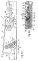
- Fig. 6 is a perspective Representation of the innentigen sensing device 11th with traction cable 16 with longitudinally cut crossbar 24 and in Figs. 6a, 6b further details shown.
- the crossbar tube 24 has a pipe on the top Longitudinal slot opening 88, in which the sensing device 11 is attached with the button 69.
- the button 69 has an approximately cuboid, down open and upwardly closed hollow shell body, consisting of two opposite, conformed TastShitONE 80,81, each having a reinforced, have inwardly directed, extensive edge area, and one located between the reinforced edge areas TastShtechnikteil 99 is, where the probe surface 97 of the three parts 80.81,99 finger- or thumb-friendly, especially wavy for manual operation can be profiled.
- the button 69 protrudes with its parts 80,81,97 out of the longitudinal slot opening 88 out.
- the longitudinal slot opening 88 adjacent is a locking tube longitudinal opening 98, preferably a narrower width as the longitudinal slot opening 88 and up to a Anorgrundkante 107 is guided.
- the button 69 is with a Button holding body 85 connected to one of the below Arretianssrohrlticiansö réelle 98 located in Traversenrohr Society Clamping body part 59 and a button holding body part 100 exists.
- the button holding body 85 is by his inner tube adapted clamping body part 59 in the Arret stressesslmoisö Maschinen 98 fastened, with the attachment by means of an associated clamping screw 57 and a clamping screw head-covered Clamping ring 58 takes place, the Diameter is greater than the width of the Arret stressessrohrlcertainsö Maschinen 98th
- the button holding body part 100 is opposite to the clamping body part 59 narrowed so that it enters the cavity of the probe 69 extends, in particular of the jacket body.
- the internal, between tube and probe cavity mounted button holding body part 100 is preferably bird-shaped and has belly bearing a pivot pin 60 for the button 69 and head / back a support spring 20 for the button 69.
- This head / back is a vertical hole-like Countersunk 92 inserted in the button holding body 85, in which a part of the support spring 20 is directed vertically is held, with its free upper end part of the button 69 in the reinforced edge area.
- the pivot pin 60 is in a first the TastShacht 90 guided, with the first slip-on slot 90th and the pivot pin 60 within the traverse tube 24 are located. While the button holding body 85 in the rear half of the button 69 is located in the front half a rocking, rocking axis inclined swivel body 83 supported on the Tast Economics product former 80,81 and pivotally mounted, wherein a first pivot transverse pin 82 at the upper end of the pivot body 83 and preferably above the crossbar tube 24 is present and in one second preferably vertical Aufsteckschacht 101 of Tastangemaschinemaschine 80,81 is performed.
- the rocking Swivel body 83 is located with the below the TastShangemaschinener 80,81 located lower bent end region the pipe inner wall 102 and has a substantially convex curved rolling surface 103, which is substantially of the bearing surface on the tube inner wall 102 to near the top End portion of the first pivoting transverse pin 82 of the pivoting body 83 extends.
- a second Schwenkquerbolzen 104 with a cable connection 84 in one Plug opening 105 is present, wherein in the plug opening 105th the trailing cable 16 end retaining swivel cross pin 104th can be introduced.
- the swivel body 83 is of the plug opening 105 starting out in the cable direction a sickle-like Guide clearance 87 with an associated, also from the Plug opening from upward convex curved Cable guide track 91 for a kink-free load of the pull rope 16 trained.
- the pivoting body 83 is in the direction of the rope 16 erected by the angle ⁇ , at the same time the Angle between the rocking axis 106 as a connecting axis between the two pivoting transverse pins 82,21 and the pipe inner wall 102 represents.
- the swivel body 83 is between guided the TastShangeis 80,81 and has about the Width of the Taststoffstoffteils 99.
- Fig. 6b is a perspective view of the adjustable and lockable with a clamping fitting 57,58 Sensing device 11 on the truss tube 24 shown in FIG. 6.
- the locking tube located in the cross tube 24 locking tube 98 contains the sprag part 59 of the button holding body 85.
- the clamping body part 59 is on its holding body support 86 rounded tube interior rounded and adapted abuts against the inner tube wall of the traverse tube 24.
- the clamping body part 59 is in the transition region of locking tube longitudinal opening 98 to the longitudinal slot opening 88 with each a left-side transverse stop edge 104 and a provided on the right-side abutment transverse edge 105, transverse to the Tube course are directed and each to the Tastangestoffteil 99 run, the little in the tube longitudinal direction ends above the holding body support 86, wherein the Tast Economics interviewmaschine 80.81 with their continuing edge areas 106,107 at the transverse stop edges 104,105 of the sprag part 59 lie in such a way that the button 69 in its normal position (in the unlocked position) in given Position is held.
- the door lock 1 has the following operation: In the opening phase of the door lock 1 is no Locking pin 6 in the rotary latch 10.
- the locking piece 66 is with its counter-toothing 62 from the limb locking gears 61 of the rotary latch members 7,8 out.
- the common Spring 77 of the rotary latch members 7,8 holds the catch 10 open by the tensile force, so that at the same time a receptiveness for the locking pin 6 on the door frame of the vehicle consists.
- the locking piece 66 thus does not engage in the limb locking toothing 61 of the rotary latch members 7, 8, but lies on the outer peripheral surfaces 71 (representative for both peripheral surfaces on the rotary latch members 7,9) at.
- the opening state of the rotary latch 10 means at the same time that the door of the vehicle is open.
- the Screwing the crosshead tube 24 at the pipe bracket angle part 17 solved so far that the truss tube 24 to the screw is pivotable.
- the screw connection of the remotely operated release mechanism on the crossbar so that it is lekssverschieblihc on the truss tube.
- the Truss tube can now in the appropriate position to a Door be brought, with the remote-controlled release device 12 by the pull rope or a corresponding rod when pivoting, depending on whether the pull rope or the rod pulled out of the truss tube by pivoting or pushed in, along the truss tube is moved.
- the truss pipe can with its the lock box opposite fastening device such as a Pipe crimping attached to the door or a door frame then, whereupon the remotely operated triggering device by tightening the adjusting screw on the truss tube is determined and optionally the crossbar on Pipe bracket is also set again.
- fastening device such as a Pipe crimping attached to the door or a door frame
- the door lock according to the invention with pivotable truss tube is advantageous in that the number of transmission levers, arranged on the truss pipe triggering device is reduced, whereby by the fact that the release mechanism or button on the truss tube with a cable or a Rod is hinged to the pawl lever and also the trigger mechanism longitudinally displaceable on the truss tube and is fixed, the truss tube in any desired Position can be pivoted.
Abstract
Description
Die Erfindung betrifft ein Türschloß nach dem Oberbegriff des Anspruch 1. Ein solches Schloß wird in EP-A1-0 849 424 beschrieben.The invention relates to a door lock according to the preamble of claim 1. Such a lock is disclosed in EP-A1-0 849 424 described.
Ein derartiges als Drehfallenschloß ausgebildetes Türschloß für eine Fahrzeugtür ist in der Druckschrift US-PS 3,666,305 beschrieben. Dort weist das Drehfallenschloß ein Paar von gegenschwenkbaren, drehbar gelagerten Drehfallengliedern auf, die einen Schließbolzen in der Drehfalle mittels eines Sperrhebels der nahbetätigbaren Auslösevorrichtung halten. Beim Betätigen bzw. Lösen des Sperrhebels durch einen Sperrhebelbetätiger verschwenken die Drehfallenglieder voneinander weg gerichtet in eine raststückentriegelte Position, die es erlaubt, daß die Fahrzeugtür geöffnet werden kann. Zum Schließen der Drehfalle ist der Sperrhebel dabei derart verschwenkbar ausgerichtet, daß er nach dem Loslassen des Sperrhebelbetätigers in den Eingriff mit den Drehfallengliedern zurückgebracht wird. Unter der Richtkraft bleibt der Sperrhebel in Stützbeziehung zu den Oberflächen der Drehfallenglieder und bewegt sich in eine Drehfallenglieder-Sperrposition, wobei die Drehfallenglieder den Schließbolzen umfassen. Jedes der Drehfallenglieder hat eine Verzahnung an seiner drehfallenrückseitigen äußeren Oberfläche vorgesehen, die derart positioniert ist, daß sie in eine Nockenfläche des Armes des Sperrhebels gegenrastend eingreifen und letztere in eine solche Drehfallengliederposition führen, daß sie im Falle einer normalen Stellung nicht verstellbar sind.Such a trained as a rotary latch lock door lock for a vehicle door is in the document US-PS 3,666,305 described. There, the rotary latch lock has a pair of counter-rotating, rotatably mounted rotary latch members on which a locking bolt in the catch by means of a Hold the locking lever of the near-actuated release device. When pressing or releasing the locking lever by a Lock lever actuators pivot the rotary latch members from each other directed away into a detent unlocked position, which allows the vehicle door to be opened can. To close the catch, the locking lever is included aligned so pivotally that he after releasing the locking lever actuator into engagement with the rotary latch members is returned. Under the straightening power remains the locking lever in supporting relation to the surfaces of Rotary latch members and moves into a rotary latch member locking position, wherein the rotary latch members the locking bolt include. Each of the rotary latch members has a toothing its rotary latch back outer surface provided which is positioned so that it is in a cam surface engage the arm of the locking lever counter-locking and the latter lead into such a rotary latch member position that they are not adjustable in the case of a normal position.
Ein anderes Kraftfahrzeugtürschloß ist aus der Druckschrift DE-OS 30 10 388 bekannt, das mit einem an einer Grundplatte angeordneten und in eine eingeschnappte und eine nicht eingeschnappte Stellung beweglichen Schnapporgan aus zwei Drehfallengliedern versehen ist, mit welchem eine Klinke zusammenwirkt, welche einen Schließbolzen in der eingeschnappten Stellung hält und diesen bei Betätigung zur Bewegung in die nicht eingeschnappte Stellung freigibt und welche über einen Betätigungshebel betätigbar ist. Zwischen dem Betätigungshebel und der Grundplatte ist eine Stift-/Schlitz-Verbindung derart vorgesehen, daß der Betätigungshebel zwischen einer Normal- und einer Betätigungsstellung beweglich und als Ganzes zwischen einer Kopplungs- und einer Entkopplungsstellung gegenüber der Klinke verschieblich ist. Der Betätigungshebel ist bei der Kopplungsstellung mit der Klinke in Eingriff bringbar und bewegt diese derart, daß der Schließbolzen freigegeben wird, wenn der Betätigungshebel die Koppelstellung einnimmt und von der Normal- in die Betätigungsstellung gebracht wird. Der Betätigungshebel ist gegenüber der Klinke im Leerlauf, wenn er sich in der Entkopplungsstellung befindet und von der Normal- in die Betätigungsstellung bewegt, ohne die Klinke zur Freigabe des Schließbolzens zu betätigen. Weiterhin ist ein Sperrhebel vorgesehen, der zwischen einer Riegel- und Entriegelstellung beweglich ist und über ein Verbindungselement mit dem Betätigungshebel in Verbindung steht, welche aus einem Vorsprung an einem Hebel und einem diesen aufnehmenden Schlitz im zweiten Hebel besteht. Der Vorsprung wirkt derart mit den Kanten des Schlitzes zusammen, daß beim Bewegen des Sperrhebels von der Entriegelin die Riegelstellung der Betätigungshebel als Ganzes von der Koppel- in die Entkoppelstellung verschoben wird. Der Schlitz ist so gestaltet, daß bei dem in Kopplungs- oder Entkopplungsstellung befindlichen und von der Normal- in die Betätigungsstellung bewegten Betätigungshebel der Vorsprung im Schlitz bewegbar ist.Another motor vehicle door lock is from the document DE-OS 30 10 388 known that with a on a base plate arranged and in a snapped and a not snapped Position movable Schnapporgan of two rotary latch members is provided, with which a pawl cooperates, which a latch bolt in the snapped Holds position and this when moving to move into unlocked position releases and which via a Operating lever is actuated. Between the operating lever and the base plate is a pin / slot connection provided such that the actuating lever between a Normal and one operating position movable and as a whole between a coupling and a decoupling position is displaceable relative to the pawl. The operating lever is in the coupling position with the pawl in engagement can be brought and moved such that the locking pin is released when the operating lever, the coupling position occupies and from the normal to the operating position is brought. The operating lever is opposite the pawl idle when it is in the decoupling position and moved from the normal to the operating position, without the pawl to release the locking pin to press. Furthermore, a locking lever is provided, which between a latch and unlock position is movable and over a connecting element with the actuating lever in connection which consists of a projection on a lever and a receiving this slot in the second lever. The projection interacts with the edges of the slot, that when moving the locking lever of the Entriegelin the locking position of the operating lever as a whole of the coupling is moved to the decoupling position. Of the Slot is designed so that in the coupling or Decoupling position and from the normal to the Operating position moving actuating lever of the projection is movable in the slot.
Ein gattungsgemäßes Fahrzeugtürschloß ist in der Druckschrift EP 0 849 424 A1 beschrieben, das ein Drehfallenschloß zum verriegelnden Schließen einer Tür, insbesondere einer Fahrzeugtür eines Traktors darstellt. Die Drehfalle aus zwei Drehfallengliedern steht mit einer Drehfallenfeder sowie einem Raststück in Zusammenwirkung, wobei die Drehfalle und das Raststück verschwenkbar sind und - das Schloß verriegelnd - zusammenwirken können. Die Verriegelung kann durch ein Hebelsystem, welches einen Betätigungshebel aufweist und auf das Raststück wirkt, gelöst werden. Das Raststück ist an einem um eine erste Achse schwenkbar gelagerten Rastarm des Hebelsystems betätigbar, der in Wirkverbindung mit einem Öffnungshebel steht, welcher um eine zweite Achse schwenkbar ist. Die erste und die zweite Achse sind parallel zueinander ausgerichtet, wobei ein Verbindungsmittel, welches jeweils ein freies Ende des Rastarmes und des Betätigungshebels in Wirkverbindung bringt, angeordnet ist. Dabei sind der Rastarm und der Betätigungshebel um ihre Schwenkachsen gleichsinnig verschwenkbar.A generic vehicle door lock is in the document EP 0 849 424 A1, which is a rotary latch lock for locking closing a door, in particular representing a vehicle door of a tractor. The catch from two rotary latch links stands with a rotary latch spring and a locking piece in cooperation, wherein the catch and the locking piece are pivotable and - the castle locking - can interact. The lock can by a lever system having an operating lever and acts on the locking piece to be solved. The locking piece is mounted on a pivotable about a first axis Locking arm of the lever system actuated, the operative connection with an opening lever, which is about a second axis is pivotable. The first and second axes are parallel aligned with each other, wherein a connecting means, which in each case a free end of the latching arm and the actuating lever brings into operative connection, is arranged. there are the locking arm and the operating lever to their pivot axes swiveled in the same direction.
Die bekannten Türschlösser lassen sich mit einem Drücker oder Hebel vom Türäußeren betätigen und mit einem zweiten Hebel aus dem Fahrzeuginneren betätigen, wobei üblicherweise von einem Fahrzeugäußeren eine Nahauslösung, d.h. ein unmittelbar am Schloß angeordneter Auslösemechanismus betätigt wird und die Betätigung von der Fahrzeuginnenseite her eine Fernauslösung bzw. Fernbetätigung ist, d.h. beispielsweise die Betätigung des Schlosses über einen Stahldraht bzw. eine Anlenkstange. The well-known door locks can be with a pusher or operate lever from the outside of the door and with a second one Operate lever from the vehicle interior, usually from a vehicle exterior, a near trigger, i. an immediate one operated on the lock trigger mechanism actuated is and the operation of the vehicle inside a Remote triggering is, i. for example the operation of the lock on a steel wire or a Tiller crossbar.
Hierbei ist von Nachteil, daß die Fernauslösung bzw. Fernbetätigung schlecht an verschiedene Türtypen anpassbar ist und daß, insbesondere bei den hohen Vibrationen in Traktoren oder anderen landwirtschaftlichen Nutzfahrzeugen Hebelsysteme mit mehrfachen Übersetzungen und Anlenkpunkten durch Vibrationen belastet und auf Dauer beschädigt wird. Ferner sind Kabinentüren von Traktoren und anderen landwirtschaftlichen Nutzfahrzeugen wie beispielsweise von Mähdreschern als Vollsichtkabinentüren, d.h. durchsichtig ohne Hohlräume ausgeführt. Derartige Türen weisen als tragende Elemente oft nur umlaufend ein Rohrsystem auf, so daß übliche Fernauslösemechnismen wie Hebel- oder Seilsysteme nicht in einem Türinneren angeordnet werden können.This has the disadvantage that the remote control or remote control badly adaptable to different door types and that, especially with the high vibrations in tractors or other agricultural vehicles lever systems with multiple translations and articulation points through Vibrations loaded and permanently damaged. Further are cabin doors of tractors and other agricultural ones Commercial vehicles such as combine harvesters as full view cabin doors, i. transparent without cavities executed. Such doors often have load-bearing elements only circulating a pipe system, so that usual Fernauslösemechnismen like lever or cable systems not in a door interior can be arranged.
Der Erfindung liegt die Aufgabe zugrunde, ein Türschloß, insbesondere für landwirtschaftliche Nutzfahrzeuge zu schaffen, das derart ausgebildet ist, daß die Fernbetätigung, insbesondere von der Fahrzeuginnenseite her, leicht an unterschiedliche Türarten bzw. -formen anpassbar und schnell an einer Tür zu montieren ist, wobei der Mechanismus besonders robust bezüglich Vibrationsbelastungen bei einfacher Montierbarkeit ist.The invention is based on the object, a door lock, especially for agricultural vehicles, which is designed such that the remote control, especially from the vehicle interior, easy to different Door types and shapes adaptable and fast to be mounted on a door, the mechanism being particularly robust with regard to vibration loads with simple Mountability is.
Die Aufgabe wird mit einem Türschloß mit den Merkmalen des Anspruch 1 gelöst, vorteilhafte Aus- und Weiterbildungen in den Unteransprüchen gekennzeichnet.The task comes with a door lock with the characteristics of Claim 1, advantageous embodiments and further developments in characterized the dependent claims.
In dem Türschloß steht erfindungsgemäß der Sperrklinkenhebel mit einer in einem Traversenrohr geführten und angeordneten fernbetätigbaren Auslösevorrichtung derart in Verbindung, daß das Traversenrohr bezüglich des Schlosskastens in zumindest eine Ebene beliebig schwenkbar ist, wobei das Traversenrohr den Fernauslösemechanismus beherbergt. Der Mechanismus ist so ausgebildet, daß das Rohr auch einen abgewinkelten geknickten Verlauf aufweisen kann ohne die Zuverlässigkeit der Mechanik negativ zu beeinflussen. Zudem ist der Betätigungshebel der Fernauslösung im Rohr längsverschieblich gelagert.In the door lock according to the invention is the pawl lever with a guided and arranged in a truss tube remotely operable triggering device in such a way, that the crossbar with respect to the lock case in at least a plane is arbitrarily pivotable, wherein the truss tube accommodates the remote release mechanism. The mechanism is designed so that the pipe is also an angled can have a bent course without the reliability to negatively influence the mechanics. In addition, the operating lever the remote release in the tube longitudinally displaceable stored.
Der Schloßkasten stellt ein muldenartiges oder kastenförmiges Behältnis dar, das als zusammenhängende Wandungsteile einen Muldenboden, eine erste Kurzseitenschloßwandung, eine zweite gegenüberliegende Kurzseitenschloßwandung sowie eine erste Langseitenschloßwandung aufweist, wobei die zweite Langseitenschloßwandung zweigeteilt aus einem ersten Schloßwandungsteil und einem zweiten Schloßwandungsteil besteht, wobei sich zwischen beiden Schloßwandungsteilen etwa mittig die Kastenöffnung befindet, durch die der Schließbolzen in den Schloßkasten hinein und aus dem Schloßkasten heraus bewegbar ist.The lock case presents a trough-like or box-shaped Container that as coherent wall parts a trough bottom, a first short side lock wall, a second opposite short side lock wall as well as one first long side lock wall, wherein the second Long side lock wall divided into two parts from a first lock wall part and a second lock wall part, being approximately centrally between the two Schloßwandungsteilen the box opening is through which the locking bolt in the lock box in and out of the lock box movable is.
Die beiden miteinander verbundenen Hebelarme des Sperrklinkenhebels sind ein vertikaler Hebelarm und ein horizontaler Hebelarm mit einem zugehörigen Winkelbereich, wobei der vertikale Hebelarm vorzugsweise endbereichsseitig das Raststück besitzt und etwa parallel zur Langseitenschloßwandung gerichtet ist und wobei der horizontale Hebelarm etwa parallel der Kurzseitenschloßwandung gerichtet ist und sich bis in den Eckbereich der Schloßwandungen neben dem oberen Drehfallenglied erstreckt.The two interconnected lever arms of the pawl lever are a vertical lever arm and a horizontal one Lever arm with an associated angle range, with the vertical Lever preferably endbereichsseitig the locking piece owns and directed approximately parallel to the Langseitenschloßwandung is and where the horizontal lever arm is approximately parallel the Kurzseitenschloßwandung is directed and extends into the corner of the Schloßwandungen next to the upper rotary latch member extends.
Der horizontale Hebelarm des Sperrklinkenhebels steht mit der fernbetätigbaren, vorzugsweise innenbetätigbaren Auslösevorrichtung und deren Fernauslösehebel in Verbindung.The horizontal lever arm of the pawl lever stands with the remotely actuated, preferably internally actuable release device and their remote release lever in conjunction.
Der der Drehfalle zugeordnete vertikale Hebelarm des Sperrklinkenhebels steht mit der griffbetätigbaren Auslösevorrichtung und deren Nahauslösehebel in Verbindung. The rotary latch associated with the vertical lever arm of the pawl lever stands with the handle-actuated release device and their proximity trigger in conjunction.
Der Fernauslösehebel und der Nahauslösehebel sind unabhängig voneinander dem Sperrklinkenhebel zugeordnet, wobei der Fernauslösehebel über jeweils ein endseitiges Eingriffselement mit dem horizontalen Hebelarm und der Nahauslösehebel mit dem vertikal gerichteten Hebelarm in Verbindung stehen.The remote release lever and the proximity release lever are independent each other assigned to the pawl lever, wherein the Remote release lever via one end-side engagement element with the horizontal lever arm and the proximity release lever communicate with the vertically directed lever arm.
Der Sperrklinkenhebel ist federunterstützt, wobei der Druck der Feder in Richtung der Drehfalle gerichtet ist.The pawl lever is spring-assisted, the pressure the spring is directed in the direction of the rotary latch.
Die türgriffbetätigbare Auslösevorrichtung ist mit einem schwenkbaren Türgriff, der in einer Türgriffmulde eingelagert ist, versehen, wobei der Türgriff mit einer an der Türgriffmulde befestigten Hebeleinrichtung und einer daran befestigten Plattform quer zur Türgriffmulde verbunden ist, wobei durch die Bewegung der Plattform der Nahauslösehebel verschwenkbar ist.The door handle actuable release device is equipped with a swiveling door handle, which is stored in a door handle recess is provided with the door handle with a door handle recess attached lever device and an attached thereto Platform is connected across the door handle recess, whereby by the movement of the platform of Nahauslösehebel is pivotable.
Die innentürig tasterbetätigbare Auslösevorrichtung besteht außerhalb des Schloßkastens aus einem vorzugsweise stufenartigen Rohrhaltewinkelteil, aus einem daran befestigten, verschwenkbaren Traversenrohr, das zum Schloßkasten gerichtet offen ist und am freien anderen Ende mit einer türangepaßt montierbaren, mit einem Langloch versehenen Rohraufquetschung versehen ist, sowie aus einer am und im Traversenrohr befindlichen Tasteinrichtung, von der aus ein mit einem Seilhaken endverstärktes Zugseil an den mit dem Rohrhaltewinkelteil in Verbindung stehenden, gelochten und seilhakenaufnahmebereiten Fernauslösehebel geführt ist.The innentürig button-actuable release device consists outside the lock case from a preferably step-like Pipe bracket angle part, from an attached, pivotable Traverse tube, which is directed to the lock case is open and with a door adapted to the free other end mountable, with a slot provided pipe crimping is provided, as well as one on and in the truss pipe located sensing device, from the one with a Rope hook end reinforced pull rope to the with the pipe bracket angle part related, perforated and rope hooks receptive Remote release lever is guided.
Das Rohrhaltewinkelteil besteht aus dem vorzugsweise randseitig am unteren Deckelteil vertikal angeformten oder befestigten Winkelteilstück, aus einem sich vom Deckelteil schloßkastenseitlich versetzten Stufendistanzteil sowie aus einem Rohrhalteteil, an dem das Traversenrohr einerseits endseitig befestigt, vorzugsweise verschraubt. The tube holding angle part consists of the preferably edge side vertically molded or attached to the lower lid part Angle section, from a part of the lid lockbox laterally staggered Stufendistanzteil and off a pipe holding part, on which the truss pipe on the one hand attached at the end, preferably screwed.
Das Rohrhaltewinkelteil stellt ein material- und formminimalisiertes Halterungs- und Abstandselement dar.The tube holding angle part represents a material and form minimalized Holding and spacer element.
Die erste Kurzseitenschloßwandung weist eine vorzugsweise rechteckige Freischnittöffnung im Eckbereich zwischen erster Langseitenschloßwandung und dem Deckelteil auf.The first short side lock wall has a preferably rectangular free cut opening in the corner between the first Long side lock wall and the lid part on.
Der Deckel ist zweigeteilt in ein unteres erstes Deckelteil und ein oberes zweites Deckelteil ausgelegt, wobei am unteren ersten Deckelteil ein um einen rechten Winkel nach außen abgewinkelter, herausragender Drehlochvorsatz vorhanden ist, an dem der Nahauslösehebel verschwenkbar gelagert verschraubt sowie das Rohrhaltewinkelteil angeformt sind, an dem das Traversenrohr befestigt ist.The lid is divided into two parts in a lower first lid part and an upper second lid part, wherein at the lower first cover part at a right angle to the outside angled, outstanding rotary-hole attachment is present, on which the Nahauslösehebel pivotally mounted bolted and the pipe bracket angle part are formed on the truss pipe is attached.
Sowohl der Drehlochvorsatz als auch das Rohrhaltewinkelteil sind im rechten Winkel zueinander vorzugsweise an einem Dekkelteil angeordnet.Both the rotary hole header and the pipe bracket angle part are at right angles to each other preferably on a Dekkelteil arranged.
Das Zugseil oder die Stange ist über den um die Achse verschwenkbar gelagerten Fernauslösehebel und dem Eingriffsfortsatz mit dem Schloßkastenfunktionsinterieur verbunden.The pull rope or the rod is pivotable about the axis about the mounted remote release lever and the engagement extension associated with the lock box feature interior.
Der Fernauslösehebel ist mittels der Drehlagerungsschraube an das Rohrhaltewinkelteil befestigt, wobei im Schloßkasten, insbesondere im unteren Deckelteil im Bereich des Fernauslösehebels ein Fenster vorgesehen ist, damit über den am Fernauslösehebel angeformten Eingriffsfortsatz der im Schloßkasten verschwenkbare Sperrklinkenhebel betätigbar ist.The remote release lever is by means of the pivot bearing screw attached to the pipe bracket portion, wherein in the lock box, especially in the lower cover part in the area of the remote release lever a window is provided so that over the am Remote release lever molded engagement extension of the Lock case pivoting pawl lever operable is.
Das Traversenrohr ist vorzugsweise mit zugehöriger, am freien Rohrende befindlicher Rohraufquetschung am Rohrhalteteil des Rohrhaltewinkelteils über den Rohrhalterungsblock und der Verschraubung einstellbar befestigt.The truss pipe is preferably associated with, at the free Pipe end befindlicher pipe crushing on the pipe holding part of the pipe bracket part over the pipe support block and the screw fastened adjustable.
Unabhängig voneinander ist mittels des Fernauslösehebels oder mittels des Nahauslösehebels der Sperrklinkenhebel betätigbar.Independent of each other is by means of the remote release lever or by means of the Nahauslösehebels the pawl lever operable.
Die beiden Auslösehebel können mit dem Sperrklinkenhebel, insbesondere mit dessen Hebelarme über weitere unterschiedliche ausgesparte und eingefügte korrespondierenden Rastelemente in Verbindung stehen.The two release levers can with the pawl lever, especially with its lever arms over more different recessed and inserted corresponding locking elements keep in touch.
Das Traversenrohr der tasterbetätigbaren Auslösevorrichtung ist an dem Rohrhalteteil des stufenartig ausgebildeten Rohrhaltewinkelteils schwenkbar befestigt, insbesondere verschraubt.The traverse tube of the button-actuable triggering device is at the tube holding part of the step-like tube holding angle part pivotally mounted, in particular screwed.
In dem Traversenrohr ist das Zugseil oder die Stange bis zur Tasteinrichtung geführt, die vorzugsweise mittig am Traversenrohr und vertikal nach oben gerichtet aus dem freigeschnitten Rohr angeordnet ist.In the truss pipe the pull rope or the rod is up to Guided sensing device, preferably centrally on the truss tube and vertically up out of the cut Tube is arranged.
Am außerhalb des Schloßkastens befindlichen Winkelteilstück ist der Fernauslösehebel mittels der Drehlagerungsschraube verschwenkbar gelagert angebracht.On located outside of the lock box angle section is the remote release lever by means of the pivot bearing screw mounted pivotally mounted.
Am Fernauslösehebel ist ein mit einem Halterungsloch versehener Seilaufnehmer angeformt, wobei das Halterungsloch den gegenüber dem Zugseil oder der Stange verstärkten Seilhaken halternd aufnimmmt und der Seilaufnehmer und der Eingriffsfortsatz vorzugsweise parallel gerichtet sind.The remote release lever is one provided with a mounting hole Seilaufnehmer molded, wherein the mounting hole the Reinforced rope hooks opposite the pull rope or the rod retaining and the Seilaufnehmer and the engaging extension are preferably directed in parallel.
Das Traversenrohr weist an der Rohroberseite vorzugsweise längsmittig eine Längsschlitzöffnung und eine Arretierungrohrlängsöffnung auf, in denen die Tasteinrichtung mit dem Taster längsverschieblich befestigt ist.The truss tube preferably has at the Rohroberseite longitudinally a longitudinal slot opening and a locking tube longitudinal opening on, in which the sensing device with the Push button is mounted longitudinally displaceable.
Der Taster ist mit einem im Rohr befindlichen Tasterhaltekörper verbunden, der aus einem der Arretierungsrohrlängsöffnung im Traversenrohrbereich zugeordneten Klemmkörperteil und aus einem dem Mantelkörper zugeordneten Tasterhaltekörperteil besteht.The pushbutton is equipped with a push-button holding body located in the tube connected, which from one of the locking tube longitudinal opening in the crossbar area associated sprag part and from a the cartridge body associated probe holding body part consists.
Außerhalb der Rohraußenwandung ist eine vorzugsweise mit einem Imbus betätigbare Klemmschraube sowie ein zwischen Klemmschraubenkopf und Rohraußenwandung befindlicher Klemmring vorgesehen, mit dem der Tasterhaltekörper und somit auch der Winkel α eines schaukelartigen Schwenkkörpers zur Rohrinnenwandung eingestellt arretierbar sind.Outside the Rohraußenwandung is a preferably with a Imbus actuated clamping screw and an intermediate Clamping screw head and clamping tube located outside the tube provided with the button holding body and thus also the angle α of a rocking swivel body to Tube inner wall are set locked.
Das Klemmkörperteil ist vorzugsweise gleich oder schmaler als die Breite der Längsschlitzöffnung zum einfachen Einbau der Tasteinrichtung in das Traversenrohr ausgebildet.The sprag part is preferably the same or narrower as the width of the longitudinal slot opening for easy installation the sensing device formed in the truss tube.
Der Klemmkörperteil ist im Übergangsbereich von Arretierungsrohrlängsöffnung zur Längsschlitzöffnung mit jeweils einer linkseitigen Anschlagquerkante und einer rechtsseitigen Anschlagquerkante versehen, die quer zum Rohrverlauf gerichtet sind und jeweils bis zum Tastkörpermittelteil verlaufen, das in Rohrlängsrichtung wenig oberhalb der Haltekörperauflage endet, wobei die Tastkörperseitenteile mit ihren weiterführenden Randbereichen an den Anschlagquerkanten des Klemmkörperteils derart anliegen, daß der Taster in seiner Normalstellung in vorgegebener Position gehaltert ist.The sprag part is in the transition region of the locking tube longitudinal opening for longitudinal slot opening with each a left-side stop transverse edge and a right-side Provide transverse stop edge, which is directed transversely to the pipe run are and in each case to the Tastkörpermittelteil run, in the tube longitudinal direction just above the holding body support ends, with the Tastkörperseitenteile with their continuing edge areas at the transverse stop edges abut the sprag part so that the button in his Normal position is held in a predetermined position.
Die Erfindung wird anhand eines Ausführungsbeispiels mittels mehrerer Zeichnungen beispielhaft näher erläutert. The invention is based on an embodiment by means of several drawings explained in more detail by way of example.
Es zeigen:
- Fig. 1
- ein erfindungsgemäßes Türschloß in Draufsicht mit einer nahbetätigbaren Auslösevorrichtung und einer fernbetätigbaren Auslösevorrichtung;
- Fig. 1a
- eine vergrößerte Darstellung des Schloßkastens und der beiden schloßkastennahen Auslösehebel der beiden betätigbaren Auslösevorrrichtungen nach Fig. 1;
- Fig. 2
- eine Draufsicht auf das Türschloß ohne Außentürmulde für die nahbetätigbare Auslösevorrichtung nach der Darstellung in Fig. 1;
- Fig. 3
- eine Seitenansicht in Richtung Deckelteile des mit zwei unterschiedlich betätigbaren Auslösevorrichtungen ausgebildeten Türschlosses nach Fig. 1;
- Fig. 4
- eine perspektivische Darstellung des wesentlichen Interieurs des erfindungsgemäßen Türschlosses mit einem Nahauslösehebel, einem Fernauslösehebel, einem Sperrklinkenhebel sowie einer mit einer Feder unterstützten Drehfalle;
- Fig. 5
- eine perspektivische Ansicht auf das Gehäuse des Schloßkastens mit daran befestigtem Traversenrohr mit innentüriger Tasteinrichtung ohne Zugseil;
- Fig. 6
- eine perspektivische Darstellung der innentürigen Tasteinrichtung mit Zugseil bei längsseitig aufgeschnittenem Traversenrohr;
- Fig. 6a
- eine Längsschnittdarstellung der Tasteinrichtung für die fernbetätigbare Auslösevorrichtung mit Traversenrohr nach Fig. 6 und
- Fig. 6b
- eine perspektivische Darstellung der verstellbaren und mit einer Klemmverschraubung arretierbaren Tasteinrichtung am Traversenrohr nach Fig. 6.
- Fig. 1
- an inventive door lock in plan view with a near-actuated release device and a remote-actuated release device;
- Fig. 1a
- an enlarged view of the lock case and the two close to the trolley closure lever of the two actuatable tripping devices of FIG. 1;
- Fig. 2
- a plan view of the door lock without outer door panel for the near-actuated release device as shown in Fig. 1;
- Fig. 3
- a side view in the direction of cover parts of the door lock formed with two differently actuated release devices of FIG. 1;
- Fig. 4
- a perspective view of the essential interior of the door lock according to the invention with a Nahauslösehebel, a Fernauslösehebel, a pawl lever and a supported with a spring catch;
- Fig. 5
- a perspective view of the housing of the lock case with attached crossbar with innentüriger sensing device without pull rope;
- Fig. 6
- a perspective view of the innentürigen sensing device with pull rope with longitudinally cut crossbar;
- Fig. 6a
- a longitudinal sectional view of the sensing device for the remote-controlled release device with traverse tube of FIG. 6 and
- Fig. 6b
- a perspective view of the adjustable and lockable with a compression fitting sensing device on the truss tube of FIG .. 6
In den Figuren 1 bis 6b werden für gleiche Teile mit gleichen Funktionen die Bezugszeichen durchgängig beibehalten.In Figures 1 to 6b are the same parts with the same Functions keep the reference numerals throughout.
Vorerst werden die Fig. 1,1a gemeinsam betrachtet. In Fig. 1
ist im wesentlichen das erfindungsgemäße Türschloß 1 mit einer
nahbetätigbaren Auslösevorrichtung 13 und mit einer
fernbetätigbaren Auslösevorrichtung 12 gezeigt.For the time being, FIGS. 1, 1a will be considered together. In Fig. 1
is essentially the door lock 1 according to the invention with a
Dabei stellt die nahbetätigbare Auslösevorrichtung 13 eine
von außerhalb der Tür vorzugsweise türgriffbetätigbare Auslösevorrichtung
dar. Die fernbetätigbare Auslösevorrichtung
12 stellt eine vorzugsweise innentürig tasterbetätigbare
Auslösevorrichtung dar.In this case, the near-actuated
Die in Fig. 1 gezeigte türgriffbetätigbare Auslösevorrichtung
13 weist außerhalb des Schloßkastens 5 einen manuell
betätigbaren schwenkbaren Türgriff 18, der in einer Türgriffmulde
15 eingelagert ist, auf, wobei der Türgriff 18
mit einer an der Türgriffmulde 15 befestigten Hebeleinrichtung
19 und einer daran befestigten Plattform 26 quer zur
Türgriffmulde 18 verbunden ist, wobei durch die Bewegung der
Plattform 26 der Nahauslösehebel 2 um die Achse 67 verschwenkbar
gelagert ist.The door handle actuatable release device shown in Fig. 1
13 has outside the lock case 5 a manual
actuatable hinged
Der Nahauslösehebel 2, wie in Fig. 1a gezeigt ist, steht innerhalb
des Schloßkastens 5 mit einem aus der Zeichnungsebene
heraus ragenden Sperrbolzen 25 in Verbindung, der bei
Verschwenkung des Nahauslösehebels 2 ebenfalls verschwenkbar
ist, wobei der Sperrbolzen 25 durch eine Druckfeder (nicht
eingezeichnet) unterstützt ist. Desweiteren weist der Nah
auslösehebel 2 einen außerhalb des Schloßkastens 5 befindlichen
Stützvorsprung 48 auf, der endseitig in Normalstellung
am Schloßkasten 5 anliegt.The
Der Nahauslösehebel 2 ist am freien Ende außerhalb des
Schloßkastens 5, um näher an der Plattform 26 herangeführt
zu werden, mit einem einen Vorsprung 72 aufweisenden, und
wie in Fig. 3 gezeigt, mit einem von der tasterbetätigbaren
Auslösevorrichtung 12 weg geneigten, leicht verdrehten Kopf
74 versehen, wobei der Kopf 74 durch eine durchgängige
Kopfaussparung 75 materialeinsparend und u.a. leichter bedienbar
ist.The
Die innentürig tasterbetätigbare Auslösevorrichtung 12 besteht
außerhalb des Schloßkastens 5 aus einem vorzugsweise
einstufigen Rohrhaltewinkelteil 17, aus einem daran befestigten,
verschwenkbaren Traversenrohr 24, das zum Schloßkasten
5 gerichtet offen ist und am freien anderen Ende eine
türangepaßt montierbare, mit einem Langloch 39 versehene
Rohraufquetschung 31 besitzt, wobei das Traversenrohr 24
über eine zur Außenmulde gerichtete abgebogene Rohrquetschverjüngung
56 in die Rohraufquetschung 31 übergeht.
Desweiteren enthält die fernbetätigbare Auslösevorrichtung
12 eine am und im Traversenrohr 24 befindliche Tasteinrichtung
11, von der aus ein mit einem Seilhaken 9 endverstärktes
Zugseil 16 an einen mit dem Rohrhaltewinkelteil 17 in
Verbindung stehenden und seilhakenaufnehmenden Fernauslösehebel
3 geführt ist.The innentürig button-
Der vorzugsweise metallische Schloßkasten 5 in den Fig. 1,1a
weist die Form einer seitlich geschlossenen Mulde auf, deren
Wandteile vorzugsweise aus einem ganzstückigen freigeschnittenen
Grundteil entsprechend passend rechtwinklig gebogen
sind, wobei in der Mulde das wesentliche Funktionsinterieur
des Türschlosses 1 enthalten ist. Der Schloßkasten 5 hat einen
Muldenboden 38, eine erste Kurzseitenschloßwandung 29
und eine zweite gegenüberliegende Kurzseitenschloßwandung 44
sowie eine erste Langseitenschloßwandung 30, wobei die zweite
Langseitenschloßwandung zweigeteilt aus einem ersten
Schloßwandungsteil 28 und einem zweiten Schloßwandungsteil
68 besteht. Auch der Deckel ist zweiteilig in ein unteres
erstes Deckelteil 78 und ein oberes zweites Deckelteil 79
ausgelegt, wobei am unteren ersten Deckelteil 78 ein um einen
rechten Winkel nach außen abgewinkelter, herausragender
Drehlochvorsatz 52 vorhanden ist, an dem der Nahauslösehebel
2 schwenkgelagert verschraubt ist, sowie ein Rohrhaltewinkelteil
17 angeformt ist, an dem das Traversenrohr 24 befestigt
ist. Sowohl der Drehlochvorsatz 52 als auch das Rohrhaltewinkelteil
17 sind im rechten Winkel zueinander angeordnet.The preferably
Die erste Kurzseitenschloßwandung 29 weist eine vorzugsweise
rechteckige Freischnittöffnung 76 im Eckbereich zwischen erster
Langseitenschloßwandung 30 und dem Deckelteil 79 auf.The first short
In Fig. 1a ist das obere Deckelteil 79 mittels der Verschraubung
51 am Muldenboden 38 und mittels der zwischengelagerten
Distanzhülsen 53,54 befestigt. Das Rohrhaltewinkelteil
17 ist am unteren Deckelteil 78 angebunden, angeformt
oder verschraubt, das ebenfalls mittels zweier Verschraubungen
(in Fig. 1,1a nicht eingezeichnet) am Muldenboden 38
fest gehaltert ist.In Fig. 1a, the
In Fig. 2 ist die Fig. 1 in Draufsicht dargestellt. Der
Schloßkasten 5 weist den Muldenboden 38, die Schloßwandungsteile
28 und 68 sowie die Kurzseitenschloßwandungen 29,44
auf. Zwischen den Schloßwandungsteilen 28,68 ist die Kastenöffnung
14 vorhanden, die für die Bewegung der Drehfallenglieder
7,8 über die Ebene der Schloßwandungsteile 28,68
hinaus vorgesehen ist.In Fig. 2, Fig. 1 is shown in plan view. Of the
Zwischen den beabstandeten Deckelteilen 78,79 ist der Nahauslösehebel
2 angeordnet, der an dem nach außen abgewinkelten
Drehlochvorsatz 52 durch die Drehlagerungsschraube 50
verschwenkbar gelagert gehaltert ist. Im Schloßkasten 5 ist
der am Nahauslösehebel 2 am anderen Ende vorhandene Sperrbolzen
25 in Richtung der Kurzseitenschloßwandung 29 angeformt.Between the spaced
Das untere Deckelteil 78 ist nicht nur ein Halterungsteil
für den Nahauslösehebel 2, sondern auch für den Fernauslösehebel
3, der verschwenkbar am an dem unteren Deckelteil 78
angeformten Rohrhaltewinkelteil 17 gelagert und gehaltert
ist.The
Das Zugseil 16 ist über den um die Achse 33 drehbar gelagerten
Fernauslösehebel 3 und dessen Eingriffsfortsatz 45 mit
dem Funktionsinterieur des Schloßkastens 5 verbunden.The
In Fig. 3 ist eine Seitenansicht von der Seite der beiden
Auslösevorrichtungen 12,13 aus gemäß Fig. 1 gezeigt. Der
Schloßkasten 5 ist, wie er in die Tür eingebaut wird, aufrecht
dargestellt. Der Muldenboden 38 weist die Kastenöffnung
14 auf, in die der Schließbolzen 6 eingreift, wenn die
Tür geschlossen wird. In der Kastenöffnung 14 verbleibt der
Schließbolzen 6 solange, solange die Drehfallenglieder 7,8
(nicht eingezeichnet) ihn halternd umgreifen.In Fig. 3 is a side view of the side of the two
Tripping
Das obere Deckelteil 79 ist durch die Verschraubungen/Drehhalterungsschrauben
51 sowie 40 einschließlich der
zwischen Muldenboden 38 und Deckelteil 79 angeordneten Distanzhülsen
in die Schloßwandungen 30,29,28 kantennivelliert
eingepaßt, während das untere Deckelteil 78 zwischen die
Schloßwandungen 30,68 nivelliert eingepaßt ist und auf der
Kurzseitenschloßwandung 44 aufliegt. Auch das zweite untere
Deckelteil 78 wird von zwei durch schloßinterne Distanzhülsen
94,95 unterstützte Verschraubungen/Drehhalterungsschrauben
43,93 gehaltert.The
Der Fernauslösehebel 3 ist mittels der Drehlagerungsschraube
47 an dem Rohrhaltewinkelteil 17 und um die Achse 33 verschwenkbar
befestigt. Im Schloßkasten 5, insbesondere im unteren
Deckelteil 78 ist im Bereich des Fernauslösehebels 3
ein vorzugsweise rechteckiges Fenster 55 vorgesehen, damit
über den am Fernauslösehebel 3 angeformten Eingriffsfortsatz
45 der im Schloßkasten 5 befindliche Sperrklinkenhebel 27
betätigbar ist.The
Der zum Nahauslösehebel 2 zugehörige Stützvorsprung 48 liegt
im belastungsfreien Falle (Normalstellung) vorzugsweise an
der Kante der Langseitenschloßwandung 30 auf. Der Nahauslösehebel
2 kann mittig eine Langlochaussparung enthalten, mit
der er zur Plattform 26 verschiebbar ist und mittels der
Drehlagerungsschraube 50 arretiert werden kann.The
Das Traversenrohr 24 mit zugehöriger Rohraufquetschung 31
ist an dem Rohrhaltewinkelteil 17 über den Rohrhalterungsblock
34 und der Verschraubung 37 einstellbar befestigt.The
Die Fig. 4,5 werden im folgenden gemeinsam betrachtet, wobei
das erfindungsgemäße Türschloß 1 in der hochkantig angegebenen
Lage in linksseitige Türen von Fahrzeugen einsetzbar
ist. Analoges gilt auch für rechtsseitige Türen. In Fig. 4
ist in einer perspektivischen Darstellung und in geöffnetem
Zustand weitgehend das Funktionsinterieur des Schloßkastens
5 des erfindungsgemäßen Türschlosses 1 gezeigt. Das Türschloß
1 enthält einen mit einer Kastenöffnung 14 versehenen,
dort einen Schließbolzen 6 des Fahrzeuges aufnehmenden
Schloßkasten 5 und den türgriffbetätigbaren Nahauslösehebel
2, wobei im Schloßkasten 5 eine durch eine Feder 77 unterstützte
Drehfalle 10 zum Umgriff des die Kastenöffnung 14
passierten Schließbolzens 6 und ein die Verdrehpositionen
der beiden Drehfallenglieder 7,8 fixierender, flach ausgebildeter
Sperrklinkenhebel 27 für einen drehfallengliederhalternden
Rasteingriff in der der Drehfalle 10 abgewandten
Gliederrastverzahnungen 61 (61 ist ein Bezugszeichen, das
stellvertretend für die Gliederrastverzahnungen der beiden
Drehfallenglieder 7,8 ist) vorhanden sind. Der flache Sperrklinkenhebel
27 weist zwei etwa rechtwinklig zueinander verlaufende
Hebelarme 63,64 auf und ist in dem zugehörigen eckbezogenen
Winkelbereich 65 mittels eines Drehhalterungsbolzens
43, der eine Distanzhülse 95 hat, verschwenkbar gelagert.
Desweiteren weist der Sperrklinkenhebel 27 ein dem
vertikalen Hebelarm 63 endseitig zugehöriges Raststück 66
auf, dessen Gegenrastverzahnung 62 den Gliederrastverzahnungen
61 gegenüberliegt und bei Schließbolzen-Umgriffpositionen
der Drehfallenglieder 7,8, die Drehfalle 10 aufrecht
haltend, in die Gliederrastverzahnungen 61 eingreift. Die
Gliederrastverzahnungen 61 haben zumindest drei Zähne, an
deren drehfallenrückseitiger äußerer Umfangsfläche 71 die
Gegenrastverzahnung 62 des Raststückes 66 anliegen oder eingreifen
kann. In Fig. 4 greift die Gegenrastverzahnung 62 in
die Gliederrastverzahnung 61 ein.FIGS. 4, 5 are considered together in the following, wherein
the door lock 1 according to the invention specified in the edgewise
Can be used in left-side doors of vehicles
is. The same applies to right-hand doors. In Fig. 4
is in a perspective view and in open
State largely the functional interior of the
Der Sperrklinkenhebel 27 steht mit der zweiten, über ein
Traversenrohr 24 geführten und angeordneten, tasterbetätigbaren
Auslösevorrichtung 12 derart in Verbindung, daß von
schloßkastenaußerhalb aus mit jeder der beiden Auslösevorrichtungen
13 und 12 über deren zugehörigen Nah- bzw.
Fernauslösehebel 2 bzw. 3 der Schließbolzen 6 aus der Drehfalle
10 lösbar ist. The pawl lever 27 is the second, via a
Erfindungsgemäß steht der horizontal verlaufende Hebelarm 64
des Sperrklinkenhebels 27 über dem Fernauslösehebel 3 mit
der fernbetätigbaren, vorzugsweise innentürbetätigbaren Auslösevorrichtung
12 in Verbindung.According to the invention, the horizontally extending lever arm 64
of the pawl lever 27 on the
Die Drehfalle 10 besteht aus zwei Drehfallengliedern - einem
oberen Drehfallenglied 7 und einem unteren Drehfallenglied 8
- , die zueinander gerichtete Auskehlungen 32,73 aufweisen
und an den entgegengesetzten drehfallenrückseitigen äußeren
Umfangsflächen 71 Gliederrastverzahnungen 61 besitzen und in
ihren zugehörigen Drehhalterungsbolzen 40,41 drehbar gelagert
sind. Die Drehhalterungsbolzen 40,41 haben jeweils Distanzhülsen
93,94, die zugleich Träger der gemeinsamen Feder
77 sind. Die Distanzhülsen aller Drehhalterungsbolzen
40,41,43,51 ermöglichen hebelauslösende und federunterstützende
Bewegungen der Drehelemente im Interieur und zugleich
eine feste gegenseitige Halterung der Schloßwandungen zueinander.The
Die beiden zueinander rechtwinklig verlaufenden Hebelarme
des vorzugsweise einteiligen Sperrklinkenhebels 27 stellen
einen vertikalen Hebelarm 63 und einen horizontalen Hebelarm
64 dar. Der vertikale Hebelarm 63 ist etwa parallel zur
Langseitenschloßwandung 30 gerichtet, wobei am vertikalen
Hebelarm 63 seitlich hebelarmabstehend und drehfallengerichtet
das Raststück 66 angebunden ist. Der angeformte horizontale
Hebelarm 64 ist etwa parallel zur Kurzseitenschloßwandung
44 gerichtet und erstreckt sich vom Winkelbereich 65
bis in den Eckbereich der Schloßwandungen 68,44 neben dem
unteren Drehfallenglied 8.The two mutually perpendicular lever arms
the preferably one-piece pawl lever 27 provide
a vertical lever arm 63 and a horizontal lever arm
64. The vertical lever arm 63 is approximately parallel to
Langseitenschloßwandung 30 directed, wherein the vertical
Lever arm 63 laterally lever-less and drehfallengerichtet
the locking piece 66 is connected. The molded horizontal
Lever arm 64 is approximately parallel to the short
Der zur Drehfalle 10 rückseitige, vertikale Hebelarm 63
steht über dem Nahauslösehebel 2 mit der türgriffbetätigbaren
Auslösevorrichtung 13 in Verbindung. Der andere dazu
rechtwinklig verlaufende, horizontale Hebelarm 64 des Sperrklinkenhebels
27 ist vom Eckbereich der beiden Schloßwandungen
44,30 bis nahe an das untere seitliche Schloßwandungsteil
68 geführt und besitzt vorzugsweise einen zur Kurzseitenschloßwandung
44 gerichteten endseitigen Hebelarmfreischnitt
46. In den Hebelarmfreischnitt 46 greift der
Eingriffsfortsatz 45 des tasterbetätigbaren Fernauslösehebels
3 ein.The rear of the
Mit dem tasterbetätigbaren Fernauslösehebel 3 und dem türgriffbetätigbaren
Nahauslösehebel 2 kann somit unabhängig
voneinander der Sperrklinkenhebel 27 betätigt werden. Dabei
können die beiden Auslösehebel 2,3 mit dem Sperrklinkenhebel
27, insbesondere mit dessen Hebelarmen 63,64 auch über anders
ausgebildete Rastelemente in Verbindung stehen.With the button-operated
In Fig. 4 ist das Türschloß 1 ohne die beiden Deckelteile
78,79 (Fig. 3) geöffnet und ein perspektivischer Einblick
dargestellt. Der Schloßkasten 5 besteht aus einem muldenartigen
bzw. kastenförmigen Behältnis. Das Behältnis weist als
zusammenhängende Wandungsteile den Muldenboden 38 sowie
rechtwinklig abgebogenen Kurzseitenschloßwandungen - eine
obere Kurzseitenschloßwandung 29 und eine untere Kurzseitenschloßwandung
44 - und die zum Muldenboden 38 ebenfalls
rechtwinklig abgebogene Langseitenschloßwandung 30 auf. Die
zur linken Langseitenschloßwandung 30 gehörende gegenüberliegende
rechte Schloßwandung ist in ein oberes rechtes
Schloßwandungsteil 28 und in ein unteres rechtes Schloßwandungsteil
68 zweigeteilt, wobei sich zwischen beiden Wandungsteilen
28,68 etwa mittig auch die im Muldenboden 38 befindliche
Kastenöffnung 14 befindet, durch die der Schließbolzen
6 in den Schloßkasten 5 hinein und aus dem Schloßkasten
5 heraus bewegbar ist.In Fig. 4, the door lock 1 without the two
Der flache, etwa rechtwinklig ausgebildete Sperrklinkenhebel
27 ist in seinem Winkelbereich 65 zwischen den beiden Hebelarmen
63,64 mittels eines Drehhalterungsbolzens 43 im Eckbereich
zwischen den Schloßwandungen 44 und 30 verschwenkbar
gelagert. Der mit dem Raststück 66 endende drehfallenabgewandte
vertikale Hebelarm 63 des Sperrklinkenhebels 27 weist
in Richtung des oberen Deckelteils 79 (nicht eingezeichnet)
einen innen vor dem Deckelteil 79 frei endenden Sperrbolzen
25 auf. Der aufrecht ausgebildete, mit dem geneigten Hebelkopf
74 frei endende, türgriffbetätigbare Nahauslösehebel 2
ist in der deckelteilparallelen Drehlagerungsschraube 50 um
die Achse 67 verschwenkbar gelagert. Die Drehlagerungsschraube
50 befindet sich, wie in den Fig. 1a,2 gezeigt, an
einem Drehlochvorsatz 52, der am unteren Deckelteil 78 etwa
längsmittig in jeweils nach außerhalb abstehender rechtwinklig
abgewinkelter Form angeformt ist. Der Nahauslösehebel 2
kann auch mittels zweier rechtwinklig angeformter Drehlochvorsätze
verschwenkbar gelagert sein, wenn am oberen Deckelteil
79 ebenfalls ein zweiter parallel gerichtet beabstandeter
Drehlochvorsatz vorhanden ist. Im Fußbereich des Nahauslösehebels
2 nahe des vertikalen Hebelarms 63 ist der seitlich
zur Kurzseitenschloßwandung 29 gerichtete Nocken 49 angeformt,
der zum aufrechten Sperrbolzen 25 querliegt. Der
aufrechte Sperrbolzen 25 ist vertikal abstehend am flachen
Hebelarm 63 gehaltert und befindet sich zwischen dem Nocken
49 und der Langseitenschloßwandung 30. Der Sperrklinkenhebel
27 kann im Bereich des Raststücks 66 zur Langseitenschloßwandung
30 gerichtet durch eine Druckfeder (verdeckt) beaufschlagt
sein. Der Nocken 49 befindet sich dabei auch über
dem Bereich der Gegenrastverzahnungen 62 des Raststückes 66.
Der Nahauslösehebel 2 besitzt an seinem Fußbereich den überstehenden
Stützvorsprung 48, der eine kontrollierte Schwenkbewegung
um die Achse 67 in Richtung der Langseitenschloßwandung
30 und zurück ermöglicht.The flat, approximately rectangular pawl lever
27 is in its
In Fig. 5 enthält die tasterbetätigbare Auslösevorrichtung
12 ein Traversenrohr 24, das mittels des am unteren rechten
Deckelteil 78 befestigten Winkelhalteteils 35 des stufenartig
ausgebildeten Rohrhaltewinkelteils 17 befestigt, insbesondere
verschraubt oder verschweißt ist und in dem das Zugseil
16 bis zur Tasteinrichtung 11 (nicht eingezeichnet) geführt
ist, die vorzugsweise mittig am Traversenrohr 24 und
vertikal nach oben gerichtet angeordnet ist.In Fig. 5 contains the button-actuable release device
12 a
Das Rohrhaltewinkelteil 17 (in Fig. 4) ist vorzugsweise einteilig
ausgebildet und besteht aus dem am unteren Deckelteil
78 angeformten Winkelteilstück 36, aus einem sich vom Dekkelteil
78 seitlich versetzten Stufendistanzteil 4 sowie aus
dem Rohrhalteteil 35, an das das Traversenrohr 24 einerseits
endseitig befestigt, vorzugsweise verschraubt oder verschweißt
gehaltert ist. Vorzugsweise stellt das Rohrhaltewinkelteil
17 mit dem unteren Deckelteil 78 sowie dem dem
Drehlochvorsatz 52 ein ganzstückiges Bauelement dar.The tube holding angle part 17 (in FIG. 4) is preferably in one piece
formed and consists of the
Am außerhalb des Schloßkastens 5 befindlichen Winkelteilstück
36 ist der Fernauslösehebel 3 mittels einer Drehlagerungsschraube
47 verschwenkbar gelagert angebracht. Der
Fernauslösehebel 3 besitzt einen Eingriffsfortsatz 45, der
durch ein Fenster 55 (Fig. 3) im unteren Deckelteil 78 hindurch
in den Schloßkasten 5 reicht und dort in den Hebelarmfreischnitt
46 des horizontalen Hebelarmes 64 hineinragt.
Dem Fernauslösehebel 3 ist ein mit einem Halterungsloch 70
versehener Seilaufnehmer 96 zugeordnet, wobei das Halterungsloch
70 einen gegenüber dem Zugseil 16 verstärkten
Seilhaken 9 halternd aufnimmmt.At located outside the
In der Fig. 4 ist auf die Darstellung der bekannten Federunterstützung
des Sperrklinkenhebels 27 wegen der leichteren
Verständlichkeit der Interieursanordnung im Schloßkasten 5
verzichtet worden. Die Feder kann sich zwischen der Langseitenschloßwandung
30 und dem Ende des vertikalen Hebelarms 63
befinden und als Druckfeder ausgebildet sein, deren Federkraft
in Drehfallenrichtung gerichtet ist.In Fig. 4 is on the representation of the known spring support
of the pawl lever 27 because of the lighter
Comprehensibility of the interior arrangement in the
Für die nähere Erläuterung der fernbetätigbaren Auslösevorrichtung
1 außerhalb des Schloßkastens 5 werden die Fig. 6,
6a,6b gemeinsam betrachtet. Dabei sind in Fig. 6 eine perspektivische
Darstellung der innentürigen Tasteinrichtung 11
mit Zugseil 16 bei längsseitig aufgeschnittenem Traversenrohr
24 sowie in den Fig. 6a,6b weitere Details dazu gezeigt.
Das Traversenrohr 24 weist auf der Rohroberseite eine
Längsschlitzöffnung 88 auf, in der die Tasteinrichtung 11
mit dem Taster 69 befestigt ist.For a more detailed explanation of the remote-actuated release device
1 outside the
Der Taster 69 weist einen etwa quaderförmigen, nach unten
offenen und nach oben geschlossenen hohlen Mantelkörper auf,
der aus zwei sich gegenüberliegenden, konform ausgebildeten
Tastkörperseitenteilen 80,81, die jeweils einen verstärkten,
nach innen gerichteten, umfassenden Randbereich aufweisen,
und aus einem zwischen den verstärkten Randbereichen befindlichen
Tastkörpermittelteil 99 besteht, wobei die Tasteroberfläche
97 der drei Teile 80,81,99 finger- bzw. daumengerecht,
insbesondere wellenförmig zur manuellen Betätigung
profiliert sein kann. Der Taster 69 ragt mit seinen Teilen
80,81,97 aus der Längsschlitzöffnung 88 heraus.The
Der Längsschlitzöffnung 88 benachbart ist eine Arretierungsrohrlängsöffnung
98, die vorzugsweise eine schmalere Breite
als die Längsschlitzöffnung 88 aufweist und die bis zu einer
Anstoßrundkante 107 geführt ist. Der Taster 69 ist mit einem
Tasterhaltekörper 85 verbunden, der aus einem unterhalb der
Arretierungsrohrlängsöffnung 98 im Traversenrohrbereich befindlichen
Klemmkörperteil 59 und aus einem Tasterhaltekörperteil
100 besteht. Der Tasterhaltekörper 85 ist durch seinen
innenrohrförmig angepaßten Klemmkörperteil 59 in der Arretierungslängsöffnung
98 befestigt, wobei die Befestigung
mittels einer zugehörigen Klemmschraube 57 und einem klemmschraubenkopfuntergelegten
Klemmring 58 erfolgt, dessen
Durchmesser größer ist als die Breite der Arretierungsrohrlängsöffnung
98.The longitudinal slot opening 88 adjacent is a locking tube
Das Tasterhaltekörperteil 100 ist gegenüber dem Klemmkörperteil
59 derart verschmälert, daß es in den Hohlraum des Tasters
69, insbesondere des Mantelkörpers hineinreicht. Das
innere, zwischen Rohr und Tasterhohlraum angebrachte Tasterhaltekörperteil
100 ist vorzugsweise vogelkörperartig ausgebildet
und besitzt bauchlings einen Drehlagerungsbolzen 60
für den Taster 69 und kopf-/rücklings eine Stützfeder 20 für
den Taster 69. Dabei ist kopf-/rücklings eine vertikale lochartige
Versenkung 92 in den Tasterhaltekörper 85 eingelassen,
in der ein Teil der Stützfeder 20 vertikal gerichtet
gehaltert ist, die mit ihrem freien oberen Endteil den Taster
69 im verstärkten Randbereich stützt. Der Drehlagerungsbolzen
60 ist in einem ersten den Tastkörperseitenteilen
80,81 zugehörigen, vorzugsweise vertikalen Aufsteckschacht
90 geführt, wobei sich der erste Aufsteckschacht 90
und der Drehlagerungsbolzen 60 innerhalb des Traversenrohres
24 befinden. Während der Tasterhaltekörper 85 in der Hinterhälfte
des Tasters 69 angeordnet ist, ist in der Vorderhälfte
ein schaukelartiger, schaukelachsengeneigter Schwenkkörper
83 an den Tastkörperseitenteilen 80,81 gehaltert und
verschwenkbar gelagert, wobei ein erster Schwenkquerbolzen
82 am oberen Ende des Schwenkkörpers 83 und vorzugsweise
oberhalb des Traversenrohres 24 vorhanden ist und in einem
zweiten vorzugsweise vertikalen Aufsteckschacht 101 der
Tastkörperseitenteile 80,81 geführt ist. Der schaukelartige
Schwenkkörper 83 liegt mit dem unterhalb der Tastkörperseitenteile
80,81 befindlichen, unteren gebogenen Endbereich an
der Rohrinnenwand 102 auf und weist eine weitgehend konvex
gekrümmte Abrollfläche 103 auf, die sich im wesentlichen von
der Auflagefläche an der Rohrinnenwand 102 bis nahe zum oberen
Endbereich des ersten Schwenkquerbolzens 82 des Schwenkkörpers
83 erstreckt. Im unteren Endbereich ist ein zweiter
Schwenkquerbolzen 104 mit einer Seilanbindung 84 in einer
Stecköffnung 105 vorhanden, wobei in die Stecköffnung 105
der das Zugseil 16 endseitig halternde Schwenkquerbolzen 104
einbringbar ist. Im Schwenkkörper 83 ist von der Stecköffnung
105 aus ausgehend in Seilrichtung ein sichelartiger
Führungsfreiraum 87 mit einer zugehörigen, ebenfalls von der
Stecköffnung aus nach oben gerichteten konvex gekrümmenten
Seilführungsbahn 91 für eine knickfreie Belastung des Zugseils
16 ausgebildet. Der Schwenkkörper 83 ist in Richtung
des Seil 16 um den Winkel α aufgerichtet, der zugleich den
Winkel zwischen der Schaukelachse 106 als Verbindungsachse
zwischen den beiden Schwenkquerbolzen 82,21 und der Rohrinnenwandung
102 darstellt. Der Schwenkkörper 83 ist zwischen
den Tastkörperseitenteilen 80,81 geführt und weist etwa die
Breite des Tastkörpermittelteils 99 auf.The button holding
Beim Drücken des Tasters 69 in Tastdruckrichtung 89 (Pfeil)
wird der Winkel α der Schwenkachsenverbindungsebene 106 und
der Rohrinnenwand 102 verkleinert. Der Schwenkkörper 83
rollt auf der Abrollfläche 103 in Seilrichtung ab und dabei
wird das Seil 16 um die Seilführungsbahn 91 gewickelt. Dadurch
wird das Seil 16 gestrafft und der Fernauslösehebel 3
betätigt, der dann über die weiteren Funktionselemente im
Innenraum des Schloßkastens 5 die Drehfalle 10 öffnet. Der
in Tastdruckrichtung 89 (Pfeil) gedrückte Taster 69 wird
nach Ende der Druckausübung durch die Stützfeder 20 wieder
in die Ausgangsposition zurückgedrückt, wobei der Schwenkkörper
83 auch den Winkel α wieder aufweist.When pressing the
In Fig. 6b ist eine perspektivische Darstellung der verstellbaren
und mit einer Klemmverschraubung 57,58 arretierbaren
Tasteinrichtung 11 am Traversenrohr 24 nach Fig. 6 gezeigt.
Die im Traversenrohr 24 befindliche Arretierungsrohrlängsöffnung
98 enthält den Klemmkörperteil 59 des Tasterhaltekörpers
85. Der Klemmkörperteil 59 ist auf seiner Haltekörperauflage
86 innenrohrwandig gerundet angepaßt und
liegt an der Innenrohrwandung des Traversenrohres 24 an.In Fig. 6b is a perspective view of the adjustable
and lockable with a clamping fitting 57,58
Außerhalb der Rohraußenwandung ist eine vorzugsweise mit einem
Imbus betätigbare Klemmschraube 57 sowie ein zwischen
Klemmschraubenkopf und Rohraußenwandung befindlicher Klemmring
58 vorgesehen, mit dem der Tasterhaltekörper 85 und somit
auch der Winkel α des schaukelartigen Schwenkkörpers 83
zur Rohrinnenwandung 102 eingestellt arretiert werden kann.
Mittels der Klemmschraube 57, des Klemmrings 58 sowie des
Klemmkörperteils 59 wird das Zugseil 16 derart gestrafft
plaziert, daß zumindest das Zugseil 16 nahezu gerade im Traversenrohr
24 verläuft und daß ein Druck auf den Taster 69
den Fernauslösehebel 3 verschwenkt. Das Klemmkörperteil 59
ist vorzugsweise nicht breiter als die Längsschlitzöffnung
88, damit ein schneller einfacher Einbau der Tasteinrichtung
11 in das Traversenrohr 24 erfolgen kann.Outside the Rohraußenwandung is a preferably with a
Imbus actuated clamping
Der Klemmkörperteil 59 ist im Übergangsbereich von Arretierungsrohrlängsöffnung
98 zur Längsschlitzöffnung 88 mit jeweils
einer linkseitigen Anschlagquerkante 104 und einer
rechtsseitigen Anschlagquerkante 105 versehen, die quer zum
Rohrverlauf gerichtet sind und jeweils bis zum Tastkörpermittelteil
99 verlaufen, das in Rohrlängsrichtung wenig
oberhalb der Haltekörperauflage 86 endet, wobei die Tastkörperseitenteile
80,81 mit ihren weiterführenden Randbereichen
106,107 an den Anschlagquerkanten 104,105 des Klemmkörperteils
59 derart anliegen, daß der Taster 69 in seiner Normalstellung
(in der nicht gelösten Stellung) in vorgegebener
Position gehaltert ist.The clamping
Das erfindungsgemäße Türschloß 1 hat folgende Funktionsweise:
In der Öffnungsphase des Türschlosses 1 befindet sich kein
Schließbolzen 6 in der Drehfalle 10. Das Raststück 66 ist
mit seiner Gegenverzahnung 62 aus den Gliederrastverzahnungen
61 der Drehfallenglieder 7,8 herausgelenkt. Die gemeinsame
Feder 77 der Drehfallenglieder 7,8 hält die Drehfalle
10 durch die Zugkraft offen, so daß zugleich eine Aufnahmebereitschaft
für den Schließbolzen 6 am Türrahmen des Fahrzeuges
besteht. Ebenso drückt die dem Sperrklinkenhebel 27
zugeordnete Druckfeder (nicht eingezeichnet) den Sperrbolzen
25 von der Langseitenschloßwandung 30 weg und das Raststück
66 liegt in einer anderen Halterungsposition an der äußeren
Umfangsfläche 71 im Bereich der Gliederrastverzahnungen 61
an.The door lock 1 according to the invention has the following operation:
In the opening phase of the door lock 1 is no
Locking pin 6 in the
In der Öffnungsphase greift das Raststück 66 somit nicht in
die Gliederrastverzahnung 61 der Drehfallenglieder 7,8 ein,
sondern liegt an den äußeren Umfangsflächen 71 (stellvertretend
für beide Umfangsflächen an den Drehfallengliedern 7,9)
an. Der Öffnungszustand der Drehfalle 10 bedeutet zugleich,
daß die Tür des Fahrzeuges geöffnet ist.In the opening phase, the locking piece 66 thus does not engage in
the limb locking toothing 61 of the
Beim Schließen der Tür passiert der Schließbolzen 6 in Richtung
S (Pfeil) die Schloßkastenöffnung 14 und wird durch den
Türschwung gegen die dem Raststück 66 nahen Bereichen der
Auskehlungen 32 und 73 derart gedrückt, daß die gemeinsame
Feder 77 gedehnt wird, wobei die Drehfallenglieder 7,8 um
die Drehhaltebolzen 40,41 verschwenkend in eine andere Position,
d.h. in den Umgriff gelangen und somit den Schließbolzen
6 fallenartig umfassen.When closing the door of the locking bolt 6 passes in the direction
S (arrow) the
Durch die Verdrehung der Drehfallenglieder 7,8 sind die
Gliederrastverzahnungen 61 der Langseitenschloßwandung 30
und somit dem Raststück 66 derart zugewendet, daß dessen Gegenverzahnung
62 in die Gliederrastverzahnungen 61 kontaktierend
eingreifen können. Damit ist die Drehfalle 10 fest
geschlossen.By the rotation of the
Beim Betätigen der fernbetätigbaren Auslösevorrichtung 12 geschieht folgendes:When operating the remotely actuable release device 12th the following happens:
Durch Drücken auf den Taster 69 wird durch das übertragende
Zugseil oder Stange 16 in Seilzugrichtung 82 (Pfeil) der in
dem Hebelarmfreischnitt 46 befindliche Eingriffsfortsatz 45
an den horizontalen Hebelarm 64 des Sperrklinkenhebels 27
gedrückt, der von der Kurzseitenschloßwandung 44 weg in
Richtung des Drehfallengliedes 8 verschwenkt wird. Dadurch
wird das am drehfallenabgewandten vertikalen Hebelarm 63 angeformte
Raststück 66 aus den beiden Gliederrastverzahnungen
61 ausgeschwenkt entrastet, so daß durch die Federkraft der
gemeinsamen Feder 77 der Drehfallenglieder 7,8 die Drehfalle
10 freigegeben wird und der Schließbolzen 6 in die Richtung
Ö (Pfeil), die Kastenöffnung 14 passierend, den Schloßkasten
5 verlassen kann, was zur Türöffnung führt. Um die Stellung
des Traversenrohres zum Schloßkasten einzustellen, wird die
Verschraubung des Traversenrohres 24 am Rohrhaltewinkelteil
17 soweit gelöst, daß das Traversenrohr 24 um die Verschraubung
verschwenkbar ist. Zudem wird die Verschraubung des
fernbetätigbaren Auslösemechanismus am Traversenrohr gelöst,
so daß diese am Traversenrohr längverschieblihc ist. Das
Traversenrohr kann nun in die entsprechende Stellung an eine
Tür gebracht werden, wobei die fernbetätigbare Auslösevorrichtung
12 durch das Zugseil bzw. eine entsprechende Stange
beim Verschwenken, je nachdem, ob das Zugseil bzw. die Stange
aus dem Traversenrohr durch das Verschwenken herausgezogen
oder hineingeschoben wird, am Traversenrohr längs
verschoben wird. Hat das Traversenrohr eine gewünschte
Schwenkstellung bezüglich des Schlosses oder bezüglich zur
Tür erreicht, kann das Traversenrohr mit seiner dem Schloßkasten
gegenüberliegenden Befestigungseinrichtung wie eine
Rohraufquetschung an der Tür bzw. einem Türrahmen befestigt
werden, worauf anschließend die fernbetätigbare Auslösevorrichtung
durch Festziehen der Stellschraube am Traversenrohr
festgelegt wird und gegebenenfalls das Traversenrohr am
Rohrhaltewinkel ebenfalls wieder festgelegt wird.By pressing the
Bei Betätigung der nahbetätigbaren Auslösevorrichtung 13 geschieht
folgendes:Upon actuation of the
Durch Zug des Türgriffes 18 wird der aufrechte, leicht geneigte
Kopf 74 des türgriffbetätigbaren Nahauslösehebels 2
in Richtung zum Traversenrohr 24 bewegt, wobei der Nahauslösehebel
2 um die Achse 67 verschwenkt wird. Dabei drückt der
angeformte Nocken 49 gegen den endseitigen federgestützten
Sperrbolzen 25 des drehfallenabgewandten vertikalen Hebelarms
63. Durch Bewegung des Sperrbolzens 25 in Richtung der
Langseitenschloßwandung 30 wird die Gegenverzahnung 62 des
Raststückes 66 aus den Gliederrastverzahnungen 61 ausgeschwenkt
entrastet, so daß die Kraft der gemeinsamen Feder
77 wirken kann. Die Drehfalle 10 wird geöffnet, wobei die
Drehfallenglieder 7,8 eine neue Verdrehposition einnehmen
und den Schließbolzen 6 aus den Auskehlungen 32,73 in Richtung
Ö (Pfeil) freigegeben. Die Tür des Fahrzeuges ist jetzt
geöffnet.By pulling the
Geschlossen wird die Drehfalle 10 durch eintritt des
Schließbolzens 6 in die Kastenöffnung 14 und durch die stoßartige
Belastung der Auskehlungen 32,73 der Drehfalllenglieder
7,8.Closed is the
Bei dem erfindungsgemäßen Türschloß mit verschwenkbarem Traversenrohr
ist von Vorteil, daß die Anzahl der Übertragungshebel,
der am Traversenrohr angeordneten Auslösevorrichtung
verringert ist, wobei dadurch, daß der Auslösemechanismus
bzw. Taster am Traversenrohr mit einem Seilzug bzw. einer
Stange am Sperrklingenhebel angelenkt ist und zudem der Auslösemechanismus
am Traversenrohr längsverschieblich und
festlegbar angeordnet ist, das Traversenrohr in jede gewünschte
Stellung verschwenkt werden kann. Da der Angriffspunkt
des Zugseils bzw. der Stange an das Rohrhaltewinkelteil
vom Dreh- bzw. Schwenkpunkt der Traverse entfernt
ist, wird beim Versschwenken des Traversenrohres das Zugseil
oder die Zugstange mehr oder weniger aus dem Traversenrohr
hinausgezogen oder in dieses hineingeschoben, wobei diese
Änderungen mit der längsverschieblichen fernbetätigbaren
Auslösevorrichtung 12 ausgeglichen werden können. In the door lock according to the invention with pivotable truss tube
is advantageous in that the number of transmission levers,
arranged on the truss pipe triggering device
is reduced, whereby by the fact that the release mechanism
or button on the truss tube with a cable or a
Rod is hinged to the pawl lever and also the trigger mechanism
longitudinally displaceable on the truss tube and
is fixed, the truss tube in any desired
Position can be pivoted. Because the attack point
of the pull rope or the rod to the pipe bracket angle part
removed from the pivot point of the traverse
is, is at the pivoting of the traverse tube, the pull rope
or the pull rod more or less from the truss pipe
pulled out or pushed into this, with this
Changes with the longitudinally movable remote-controlled
Triggering
- 11
- Türschloßdoor lock
- 22
- Nahauslösehebellocal-release lever
- 33
- FernauslösehebelRemote release lever
- 44
- StufendistanzteilStages spacer
- 55
- Schloßkastenlock box
- 66
- Schließbolzenlocking pin
- 77
- oberes DrehfallengliedUpper rotary latch member
- 88th
- unteres Drehfallengliedlower rotary latch member
- 99
- Seilhakentow hooks
- 1010
- Drehfallecatch
- 1111
- Tasteinrichtungsensing device
- 1212
- fernbetätigbare Auslösevorrichtungremotely actuable release device
- 1313
- nahbetätigbare Auslösevorrichtungclose-acting release device
- 1414
- Kastenöffnungbox opening
- 1515
- TürgriffmuldeDoor handle recess
- 1616
- Zugseilrope
- 1717
- RohrhaltewinkelteilPipe bracket portion
- 1818
- Türgriffdoor handle
- 1919
- TürgriffhebeleinrichtungDoor handle lever means
- 2020
- Tasterfederbutton spring
- 2121
- unterer Schwenkquerbolzenlower swivel cross pin
- 2222
- Stecköffnungplug-in opening
- 2323
- Schaukelachseswing axis
- 2424
- Traversenrohrcrossmember tube
- 2525
- Sperrbolzenlocking pin
- 2626
- Plattformplatform
- 2727
- SperrklinkenhebelRatchet lever
- 2828
- SchloßwandungsteilSchloßwandungsteil
- 2929
- obere Kurzseitenschloßwandungupper short side lock wall
- 3030
- LangseitenschloßwandungLangseitenschloßwandung
- 3131
- RohraufquetschungRohraufquetschung
- 3232
- Auskehlunggroove
- 3333
- Drehachse axis of rotation
- 3434
- RohrhalterungsblockTube mounting block
- 3535
- RohrhalteteilPipe holding member
- 3636
- WinkelteilstückAngle section
- 3737
- RohrverschraubungTube Fitting
- 3838
- Muldenbodendepression base
- 3939
- LanglochLong hole
- 4040
- DrehhaltebolzenRotary retaining pin
- 4141
- DrehhaltebolzenRotary retaining pin
- 4242
- Anstoßkanteabutting edge
- 4343
- DrehhalterungsschraubeSwivel mount screw
- 4444
- untere Kurzseitenschloßwandunglower short side lock wall
- 4545
- EingriffsfortsatzEngaging extension
- 4646
- HebelarmfreischnittHebelarmfreischnitt
- 4747
- DrehlagerungschraubeRotary mounting screw
- 4848
- Stützvorsprungsupporting projection
- 4949
- Nockencam
- 5050
- DrehlagerungsschraubeRotary mounting screw
- 5151
- Verschraubungscrew
- 5252
- DrehlochvorsatzPivot hole intent
- 5353
- DistanzhülseStand Off
- 5454
- DistanzhülseStand Off
- 5555
- Fensterwindow
- 5656
- RohrquetschverjüngungRohrquetschverjüngung
- 5757
- Klemmschraubeclamping screw
- 5858
- KlemmmringKlemmmring
- 5959
- KlemmkörperteilClamp body part
- 6060
- Drehlagerungpivot bearing
- 6161
- GliederrastverzahnungenMembers of locking teeth
- 6262
- GegenrastverzahnungAgainst locking teeth
- 6363
- vertikaler Hebelarmvertical lever arm
- 6464
- horizontaler Hebelarmhorizontal lever arm
- 6565
- Winkelbereichangle range
- 6666
- Raststücklocking piece
- 6767
- Achseaxis
- 6868
- Schloßwandungsteil Schloßwandungsteil
- 6969
- Tasterbutton
- 7070
- Halterungslochsupporting hole
- 7171
- äußere Umfangsflächeouter peripheral surface
- 7272
- Vorsprunghead Start
- 7373
- Auskehlunggroove
- 7474
- Kopfhead
- 7575
- Kopfaussparunghead recess
- 7676
- FreischnittöffnungCut-out opening
- 7777
- gemeinsame Federcommon spring
- 7878
- unteres Deckelteillower cover part
- 7979
- oberes DeckelteilUpper lid part
- 8080
- TastkörperseitenteilTastkörperseitenteil
- 8181
- TastkörperseitenteilTastkörperseitenteil
- 8282
- erster oberer Schwenkquerbolzenfirst upper swivel cross pin
- 8383
- Schwenkkörperpivoting body
- 8484
- Seilanbindungrope access
- 8585
- TasterhaltekörperProbe holding body
- 8686
- HaltekörperauflageHolding body support
- 8787
- FührungsfreiraumGuide space
- 8888
- LängsschlitzöffnungLongitudinal slot opening
- 8989
- TastdruckrichtungTastdruckrichtung
- 9090
- erster Aufsteckschachtfirst slip-on shaft
- 9191
- SeilführungsbahnRope guideway
- 9292
- Versenkungsinking
- 9393
- DistanzhülseStand Off
- 9494
- DistanzhülseStand Off
- 9595
- DistanzhülseStand Off
- 9696
- SeilaufnehmerSeilaufnehmer
- 9797
- Tasteroberflächebutton surface
- 9898
- ArretierungsrohrlängsöffnungArretierungsrohrlängsöffnung
- 9999
- TastkörpermittelteilTastkörpermittelteil
- 100100
- TasterhaltekörperteilButton retaining body member
- 101101
- zweiter Aufsteckschachtsecond slip-on shaft
- 102102
- Rohrinnenwandunginner tube wall
- 103103
- Abrollfläche rolling surface
- 104104
- AnschlagquerkanteStop transverse edge
- 105105
- AnschlagquerkanteStop transverse edge
- 106106
- Randbereichborder area
- 107107
- Randbereichborder area
- αα
- Winkelangle
- ÖÖ
- Öffnungsrichtungopening direction
- SS
- Schließrichtungclosing direction
Claims (64)
- Door lock, in particular for agricultural vehicles such as tractors, containing a lock case (5), which is provided with a case opening (14) and accommodates a locking bolt (6), and a locally actuable release arrangement (13), it being the case that provided in the lock case (5) are spring-assisted rotary-latch elements (7, 8), for engaging around the locking bolt (6), and a catch lever (27) which fixes the rotary positions of the two rotary-latch elements (7, 8), belongs to the release arrangement (13) and is intended for rotary-latch-element securing engagement in the latching-action element-toothing formations (61), which are directed away from the rotary latch (10), it being the case that the catch lever (27) has two lever arms (63, 64), directed approximately at right angles to one another, and is mounted pivotably in the angle region (65) and has a latching member (66) which belongs to the end side of one lever arm (63) and of which the mating latching-action toothing formation (62) is located opposite the latching-action element-toothing formations (61) and, when the rotary-latch elements (7, 8) engage around the locking bolt, engages in the latching gaps of the latching-action element-toothing formations (61), characterized in that the catch lever (27) is connected to a second, remotely actuable release arrangement (12), which is guided and arranged in a crossmember tube (24) which can be pivoted in relation to the lock case, the release arrangement (12) being connected to the catch lever (27) via a cable or a rod (16), and the release arrangement (12) being arranged on the crossmember tube (24) such that it can be displaced longitudinally and secured, with the result that the crossmember tube (24) can be pivoted in relation to the lock case (5) and the release arrangement (12) can be adapted to the pivot angle.
- Door lock according to Claim 1, characterized in that the locally actuable release arrangement (13) constitutes a release arrangement which can be actuated preferably by a door handle from outside the door, and the remotely actuable release arrangement (12) constitutes a release arrangement which can be actuated by a button preferably inside the door.
- Door lock according to Claim 1 or 2, characterized in that the lock case (5) constitutes a depression-like or case-like container which has, as contiguous wall parts, a depression base (38), a first short-side lock wall (29), a second, opposite short-side lock wall (44) and a first long-side lock wall (30), the second long side lock wall being divided in two and comprising a first lock-wall part (28) and a second lock-wall part (68), the case opening (14) being located approximately centrally between the two lock-wall parts (28, 68), and it being possible for the locking bolt (6) to be moved into the lock case (5) and out of the lock case (5) through said opening.
- Door lock according to at least one of the preceding claims, characterized in that the two interconnected lever arms (63, 64) of the catch lever (27) constitute a vertical lever arm (63) and a horizontal lever arm (64), the vertical lever arm (63) having the latching member (66) and being directed approximately parallel to the long-side lock wall (30), and the horizontal lever arm (64) being directed approximately parallel to the short-side lock wall (44) and extending into the corner region of the lock walls (68, 44), alongside the bottom rotary-latch element (8).
- Door lock according to at least one of the preceding claims, characterized in that the horizontal lever arm (64) of the catch lever (27) is connected to the remotely actuable release arrangement (12), which can be actuated preferably from the inside, and the remote-release lever (3) thereof.
- Door lock according to at least one of the preceding claims, characterized in that the vertical lever arm (63) of the catch lever (27), said arm being assigned to the rotary latch (10), is connected to the handle-actuable release arrangement (13) and the local-release lever (2) thereof.
- Door lock according to at least one of the preceding claims, characterized in that the catch lever (27) is spring-assisted, the pressure of the spring being directed in the direction of the rotary latch (10).
- Door lock according to at least one of the preceding claims, characterized in that the remote-release lever (3) and the local-release lever (2) are assigned to the catch lever (27) independently of one another, the remote-release lever (3) being connected to the horizontal lever arm (64) via an end-side engagement element (45) in each case, and the local-release lever (2) being connected to the associated, vertically directed lever arm (63).
- Door lock according to at least one of the preceding claims, characterized in that the door-handle-actuable release arrangement (13) is provided with a pivotable door handle (18) which is incorporated in a door-handle depression (15), the door handle (18) being connected to a lever device (19), fastened on the door-handle depression (15), and a platform (26), fastened on said lever device, in the direction transverse to the door-handle depression (15), the local-release lever (2) being mounted pivotably by virtue of the movement of the platform (26).
- Door lock according to at least one of the preceding claims, characterized in that the local-release lever (2) is connected, within the lock case (5), to the blocking bolt (25), which projects vertically from the vertical lever arm (63) and, when the local-release lever (2) is pivoted, can be pivoted out of the rotary-latch-element toothing formation.
- Door lock according to at least one of the preceding claims, characterized in that the local-release lever (2) has a supporting protrusion (48) which, in the normal position, butts against the lock case (5).
- Door lock according to at least one of the preceding claims, characterized in that the local-release lever (2) is provided with a head (74) which has a protrusion (72) and is inclined away from the button-actuable release arrangement (12), a through-passage (75) of the head (74) reducing the amount of material required for said head and rendering the latter, inter alia, easier to operate.
- Door lock according to at least one of the preceding claims, characterized in that the release arrangement (12), which can be actuated by a button inside the door, comprises, outside the lock case (5), a preferably single-step tube-retaining angle part (17), a pivotable crossmember tube (24), which is fastened on said angle part, is open in the direction of the lock case (5) and is provided at the other, free end with a tube crimping formation (31) which can be installed in a door-adapted manner and is provided with a slot (39), and also comprises a contact device (11), which is located on and in the crossmember tube (24) and from which a tension cable (16), reinforced at the end by a cable hook (9), is guided to a perforated remote-release lever (3), which is connected to the tube-retaining angle part (17) and is ready for accommodating the cable hook.
- Door lock according to at least one of the preceding claims, characterized in that the tube-retaining angle part (17) comprises the angle-part member (36), which is fastened or integrally formed preferably on the border side of the bottom cover part (78), a step spacer part (4), which is offset to the side of the lock case from the cover part (78), and the tube-retaining part (35), one end side of the crossmember tube (24) being fastened thereon, preferably screwed or welded thereto.
- Door lock according to at least one of the preceding claims, characterized in that the tube-retaining angle part (17) constitutes a securing and spacer element which is minimalized in terms of material and shape.
- Door lock according to at least one of the preceding claims, characterized in that the first short-side lock wall (29) has a preferably rectangular cutout opening (76) in the corner region, between the first long-side lock wall (30) and the cover part (79).
- Door lock according to at least one of the preceding claims, characterized in that the cover is divided in two into a first, bottom cover part (78) and a second, top cover part (79), there being provided on the first, bottom cover part (78) a projecting rotary-hole extension (52) which is angled outwards at right angles, to which the local-release lever (2) is screwed in a pivotably mounted manner, and on which the tube-retaining angle part (17) is integrally formed, the crossmember tube (24), which protects the tension cable (16), being fastened on said angle part.
- Door lock according to at least one of the preceding claims, characterized in that both the rotary-hole extension (52) and the tube-retaining angle part (17) are arranged preferably on a cover part (78), at right angles to one another.
- Door lock according to at least one of the preceding claims, characterized in that the top cover part (79) is fastened, by means of at least two screw-connections (51, 40) on the depression base (38), preferably by means of the associated, interposed spacer sleeves (53, 54, 93) inside the lock case.
- Door lock according to at least one of the preceding claims, characterized in that the tube-retaining angle part (17) is attached to, integrally formed on or screwed to the bottom cover part (78).
- Door lock according to at least one of the preceding claims, characterized in that the bottom cover part (78) is secured firmly on the depression base (38) preferably by means of at least two screw-connections (41, 43) and associated spacer sleeves (94, 95) inside the lock case.
- Door lock according to at least one of the preceding claims, characterized in that also provided between the lock-wall parts (28, 68) is the case opening (14), which is provided for the movement of the rotary-latch elements (7, 8) beyond the plane of the lock-wall parts (28, 68).
- Door lock according to at least one of the preceding claims, characterized in that arranged between the spaced-apart cover parts (78, 79) is the local-release lever (2), which is secured in a pivotably mounted manner on the rotary-hole extension (52), angled outwards at right angles, by means of the rotary-mounting screw (50), of which the axis (67) is directed largely parallel to the vertical lever arm (63).
- Door lock according to at least one of the preceding claims, characterized in that the bottom cover part (78) is a securing part for the local-release lever (2) and for the remote-release lever (3), which is mounted pivotably on the tube-retaining angle part (17), which is integrally formed on the cover part (78).
- Door lock according to at least one of the preceding claims, characterized in that the tension cable (16) is connected to the functional interior of the lock case via the engagement continuation (45) and the remote-release lever (3), which is mounted such that it can be pivoted about the axis (33).
- Door lock according to at least one of the preceding claims, characterized in that the top cover part (79) is fitted in an edge-levelled manner into the lock walls (30, 29, 28) by means of the screw-connections (51, 40) including the spacer sleeves (53, 54; 93), which are arranged between the depression base (38) and cover part (79), while the bottom cover part (78) is fitted in a levelled manner between the lock walls (30, 68) and rests on the short-side lock wall (44).
- Door lock according to at least one of the preceding claims, characterized in that the remote-release lever (3) is fastened on the tube-retaining angle part (17) by means of the rotary-mounting screw (47), a window (55) being provided in the lock case (5), in particular in the bottom cover part (78), in the region of the remote-release lever (3), in order that the catch lever (27), which can be pivoted in the lock case (5), can be actuated via the engagement continuation (45), which is integrally formed on the remote-release lever (3).
- Door lock according to at least one of the preceding claims, characterized in that, in the loading-free case, the supporting protrusion (48), which belongs to the local-release lever (2), butts against the edge of the long-side lock wall (30).
- Door lock according to at least one of the preceding claims, characterized in that the crossmember tube (24), preferably with associated tube crimping formation (31) located at the free tube end, is fastened on the tube-retaining part (35) of the tube-retaining angle part (17) such that it can be adjusted via the tube-securing block (34) and the screw-connection (37).
- Door lock according to at least one of the preceding claims, characterized in that the rotary latch (10) comprises two rotary-latch elements - a top rotary-latch element (7) and a bottom rotary-latch element (8), - which have recesses (32, 73), directed towards one another, and have latching-action element-toothing formations (61) on the opposite, outer circumferential surfaces (71), on the rear side of the rotary latch, and are mounted rotatably in their associated rotary securing bolts (40, 41), the rotary securing bolts (40, 41) each having enclosing spacer sleeves (93, 94) which, at the same time, bear the common spring (77).
- Door lock according to at least one of the preceding claims, characterized in that the enclosing spacer sleeves of all the rotary securing bolts (40, 41, 43, 51) give lever-releasing and spring-assisting movements of the rotary elements in the interior and, at the same time, secure the depression base (38) and cover parts (78, 79) firmly in relation to one another.
- Door lock according to at least one of the preceding claims, characterized in that the catch lever (27) can be actuated by means of the remote-release lever (3) or by means of the local-release lever (2) independently of one another.
- Door lock according to at least one of the preceding claims, characterized in that the two release levers (2; 3) are connected to the catch lever (27), in particular the lever arms (63, 64) thereof, via recessed latching-element pairs which are introduced.
- Door lock according to at least one of the preceding claims, characterized in that the. flat catch lever (27), which is of approximately right-angled design, is secured pivotably in the corner region between two lock walls (44, 30) by a rotary securing bolt (43) located in the angle region (65).
- Door lock according to at least one of the preceding claims, characterized in that in the direction of the top cover part (79), in the latching-member region, the vertical lever arm (63) of the catch lever (27), said lever arm terminating with the latching member (66) and being directed away from the rotary latch, has a blocking bolt (25) which terminates freely in front of the top cover part (79) and is directed vertically in relation to the lever arm (63).
- Door lock according to at least one of the preceding claims, characterized in that the upright, freely terminating local-release lever (2), which is provided with an inclined lever head (74) is mounted such that it can be pivoted about the axis (67) by means of the rotary-mounting screw (50), the rotary-mounting screw (50) being located on a rotary-hole extension (52) which is provided on the bottom cover part (78), approximately in the longitudinal centre, in a form in which it is angled at right angles and projects respectively to the outside of the lock case.
- Door lock according to at least one of the preceding claims, characterized in that the local-release lever (2) is secured pivotably by means of two rotary-hole extensions which are spaced apart in parallel, an associated, identical rotary-hole extension being provided on the top cover part (79).
- Door lock according to at least one of the preceding claims, characterized in that in the foot region of the local-release lever (2), in the vicinity of the vertical lever arm (63), a cam (49), directed to the side of the short-side lock wall (29) is integrally formed as an associated counterpart to the transversely located blocking bolt (25).
- Door lock according to at least one of the preceding claims, characterized in that the cam (49) is located above the region of the mating latching-action toothing formations (62) of the latching member (66).
- Door lock according to at least one of the preceding claims, characterized in that the catch lever (27), in the region of the latching member (66), is forced in the direction of the long-side lock wall (30) by means of a compression spring.
- Door lock according to at least one of the preceding claims, characterized in that, on its foot region, the local-release lever (2) has the projecting supporting protrusion (48), which allows a controlled pivoting movement about the axis (67) of the rotary-hole extension (52) in the direction of the long-side lock wall (30) and back.
- Door lock according to at least one of the preceding claims, characterized in that the crossmember tube (24) of the button-actuable release arrangement (12) is fastened on, in particular screwed or welded to, the tube-retaining part (35) of the step-like tube-retaining angle part (17).
- Door lock according to at least one of the preceding claims, characterized in that, in the crossmember tube (24), the tension cable (16) is guided up to the contact device (11), which is arranged preferably centrally on the crossmember tube (24) and is directed vertically upwards out of the cut-open tube (24).
- Door lock according to at least one of the preceding claims, characterized in that on the angle-part member (36), which is located outside the lock case (5), the remote-release lever (3) is provided in a pivotably mounted manner by means of the rotary-mounting screw (47).
- Door lock according to at least one of the preceding claims, characterized in that integrally formed on the remote-release lever (3) is a cable mount (96) which is provided with a securing hole (70), the securing hole (70) securing a cable hook (9) which is reinforced in relation to the tension cable (16), the cable mount (96) and the engagement continuation (45) being directed preferably in parallel.
- Door lock according to at least one of the preceding claims, characterized in that the spring assigned to the catch lever (27) is located between the long-side lock wall (30) and the end of the vertical lever arm (63) and is designed as a compression spring.
- Door lock according to at least one of the preceding claims, characterized in that the crossmember tube (24) has on its top side, preferably in the longitudinal centre, a longitudinal-slot opening (88) and an arresting-action longitudinal tube opening (98), in which the contact device (11) with the button (69) is fastened.
- Door lock according to at least one of the preceding claims, characterized in that the button (69) has an approximately cuboidal lateral body which is open at the bottom and closed at the top, is hollow overall and comprises two mutually opposite, conforming contact-body side parts (80, 81), with reinforced border regions located opposite one another, and an interposed contact-body centre part (99), which is located between said side parts and is at least of the same thickness in the border regions, the contact surface (97) of the three parts (80, 81, 99) being profiled optionally in accordance with a finger or thumb for manual actuation.
- Door lock according to at least one of the preceding claims, characterized in that the button (69) projects from the longitudinal-slot opening (88), the adjacent arresting-action longitudinal tube opening (98) preferably having a narrower width than the longitudinal-slot opening (88).
- Door lock according to at least one of the preceding claims, characterized in that the button (69) is connected to a button-retaining body (85) which is located in the tube (24) and comprises a clamping-body part (59), which is assigned to the arresting-action longitudinal tube opening (98) in the crossmember-tube region, and a button-retaining-body part (100) assigned to the button cavity.
- Door lock according to at least one of the preceding claims, characterized in that the button-retaining body (85) is fastened in the arresting-action longitudinal opening (98) on the crossmember tube (24) by its clamping-body part (59), the surface of which is adapted to the inside of the tube, the fastening taking place by means of an associated clamping screw (57), which can be actuated from the outside, and of a clamping ring (58), which is located beneath the screw head, rests on the arresting-action longitudinal tube opening (98) and of which the diameter is greater than the width of the arresting-action longitudinal tube opening (98).
- Door lock according to at least one of the preceding claims, characterized in that the button-retaining-body part (100) is narrowed in relation to the clamping-body part (59) such that it extends into the preferably rear cavity of the button (69) and is designed like the body of a bird and has, on the front side, a rotary-mounting bolt (60) located transversely to the tube and, on the head/rear side, a supporting spring (20) for the button (69), the supporting spring (20) being guided vertically onto the button (69) on the inside.
- Door lock according to at least one of the preceding claims, characterized in that a hole-like indent (92) is made on the head/rear side of the button-retaining body (85), the supporting spring (20) being secured vertically in said indent and supporting the cavity of the button (69) by way of its free, top end.
- Door lock according to at least one of the preceding claims, characterized in that the transversely located rotary-mounting bolt (60) is guided in a first vertical plug-on shaft (90) belonging to the contact-body side parts (80, 81), the first plug-on shaft (90) and the rotary-mounting bolt (60) being located within the button (69).
- Door lock according to at least one of the preceding claims, characterized in that the button-retaining body (85) is arranged preferably in the region of the rear half of the button (69) and, in the front half of the latter, a rocker-like pivoting body (83) with an inclined rocker axis is secured and mounted pivotably on the contact-body side parts (80, 81), a first transverse pivoting bolt (82) being provided at the top end of the pivoting body (83) and preferably outside the crossmember tube (24), in the cavity of the button (69), and being guided in a second vertical plug-on shaft (101).
- Door lock according to at least one of the preceding claims, characterized in that the rocker-like pivoting body (83) rests by way of the bottom end region, which is located beneath the contact-body side parts (80, 81), on the bottom inner tube wall (102) and, beginning there, has a largely convexly curved rolling surface (103) which extends essentially from the bearing surface on the inner tube wall (102) to the top end region of the first transverse pivoting bolt (82) of the pivoting body (83).
- Door lock according to at least one of the preceding claims, characterized in that provided in the bottom end region of the pivoting body (83) is a second transversely located transverse pivoting bolt (21), with a cable attachment (84) in a transversely located plug-in opening (22).
- Door lock according to at least one of the preceding claims, characterized in that formed in the pivoting body (83), extending in the cable direction from the plug-in opening (22), is a crescent-like guide clearance (87) for inflection-free loading of the tension cable (16).
- Door lock according to at least one of the preceding claims, characterized in that the pivoting body (83) in the normal position is in an upright state, in the cable-attachment direction, by the angle (α), which is provided between the rocker axis (23), between the two transverse pivoting bolts (21, 82), and the inner tube wall (102).
- Door lock according to at least one of the preceding claims, characterized in that, when the button (69) is pushed in the pushing direction (89), the angle (α) can be reduced and the pivoting body (83) rolls on the rolling surface (103) in the cable-attachment direction and, in the process, the tension cable (16) winds around the curved cable-guiding path (91) in the guide clearance (87) with the exertion of tension.
- Door lock according to at least one of the preceding claims, characterized in that the arresting-action longitudinal tube opening (98), which is located in the crossmember tube (24), contains the clamping-body part (59) of the button-retaining body (85), the clamping-body part (59) being rounded in adaptation to the inner tube wall and butting against the inner wall of the crossmember tube (24).
- Door lock according to at least one of the preceding claims, characterized in that provided outside the outer tube wall are a clamping screw (57), which can be actuated preferably by a socket-head-screw wrench, and a clamping ring (58), which is located between the clamping-screw head and outer tube wall and by means of which the button-retaining body (85), and thus also the angle (α) of the rocker-like pivoting body (83), can be arrested in a manner in which they have been adjusted in relation to the inner tube wall (102).
- Door lock according to at least one of the preceding claims, characterized in that the clamping-body part (59) is designed to be preferably equal to or narrower than the width of the longitudinal-slot opening (88), for straight-forward installation of the contact device (11) in the crossmember tube (24).
- Door lock according to at least one of the preceding claims, characterized in that, in the transition region from the arresting-action longitudinal tube opening (98) to the longitudinal-slot opening (88), the clamping-body part (59) is provided respectively with a left-hand transverse stop edge (104) and a right-hand transverse stop edge (105), which are directed transversely to the progression of the tube and each run up to the contact-body centre part (99), which terminates, in the longitudinal direction of the tube, a little way above the retaining-body bearing (86), the contact-body side parts (80, 81) butting, by way of their continuing border regions (106, 107), against the transverse stop edges (104, 105) of the clamping-body part (59) such that the button (69) is secured in a predetermined state in its normal position.
Applications Claiming Priority (2)
| Application Number | Priority Date | Filing Date | Title |
|---|---|---|---|
| DE19952012A DE19952012A1 (en) | 1999-10-28 | 1999-10-28 | Door lock, especially for tractors |
| DE19952012 | 1999-10-28 |
Publications (3)
| Publication Number | Publication Date |
|---|---|
| EP1096086A2 EP1096086A2 (en) | 2001-05-02 |
| EP1096086A3 EP1096086A3 (en) | 2003-01-02 |
| EP1096086B1 true EP1096086B1 (en) | 2004-05-19 |
Family
ID=7927214
Family Applications (1)
| Application Number | Title | Priority Date | Filing Date |
|---|---|---|---|
| EP00122017A Expired - Lifetime EP1096086B1 (en) | 1999-10-28 | 2000-10-10 | Door lock, in particular for tractors |
Country Status (4)
| Country | Link |
|---|---|
| US (1) | US6419284B1 (en) |
| EP (1) | EP1096086B1 (en) |
| AT (1) | ATE267321T1 (en) |
| DE (2) | DE19952012A1 (en) |
Cited By (1)
| Publication number | Priority date | Publication date | Assignee | Title |
|---|---|---|---|---|
| EP2508696A2 (en) | 2011-04-09 | 2012-10-10 | HAPPICH GmbH | Locking system for doors and flaps of all kinds |
Families Citing this family (22)
| Publication number | Priority date | Publication date | Assignee | Title |
|---|---|---|---|---|
| US7111879B2 (en) | 2002-12-11 | 2006-09-26 | Tri/Mark Corporation | Latch assembly for movable closure element |
| US7309087B2 (en) * | 2002-12-11 | 2007-12-18 | Tri/Mark Corporation | Latch assembly for movable closure element |
| US7097216B2 (en) * | 2002-12-11 | 2006-08-29 | Tri/Mark Corporation | Latch assembly for movable closure element |
| US7289527B2 (en) * | 2002-12-12 | 2007-10-30 | International Business Machines Corporation | Admission control in networked services |
| US7338097B2 (en) * | 2003-03-11 | 2008-03-04 | Tri/Mark Corporation | Latch assembly for a movable closure element |
| US7198308B2 (en) * | 2004-03-29 | 2007-04-03 | Tri/Mark Corporation | Operating mechanism for a movable closure element |
| DE102006012956A1 (en) * | 2005-09-27 | 2007-03-29 | D. la Porte Söhne GmbH | Rotary latch lock for vehicle e.g. tractor, door, has actuating lever in contact with catches to actuate catches, and key provided for finding, centering and guiding door with respect to vehicle body while opening and closing door |
| US7988210B2 (en) * | 2006-10-20 | 2011-08-02 | Kubota Corporation | Cabin door device |
| DE202007005292U1 (en) | 2007-04-12 | 2007-06-21 | D. la Porte Söhne GmbH | Near and remote controllable vehicle door lock e.g. for tractors, has turning lock arrangement and release mechanism so that lock is unlockable and lock has casing having recess for closing pin |
| US8091933B1 (en) * | 2007-09-21 | 2012-01-10 | Trimark Corporation | Heavy duty door latch and release modules |
| US8011699B2 (en) * | 2007-10-04 | 2011-09-06 | Tri Mark Corp | Cable actuated latch system |
| DE202008005128U1 (en) * | 2008-04-14 | 2008-07-10 | D. la Porte Söhne GmbH | Vehicle door lock with internal release lever |
| US8770635B2 (en) * | 2011-04-20 | 2014-07-08 | Trimark Corporation | Grapple style compression latch |
| US9175505B2 (en) * | 2013-02-06 | 2015-11-03 | Honda Motor Co., Ltd. | Door handle assemblies and vehicles having same |
| US9221319B2 (en) * | 2013-02-22 | 2015-12-29 | Komatsu Ltd. | Cab for construction machine and construction machine |
| JP5319029B1 (en) * | 2013-02-22 | 2013-10-16 | 株式会社小松製作所 | Construction machinery cab and construction machinery |
| JP5490297B1 (en) | 2013-09-02 | 2014-05-14 | 株式会社小松製作所 | Construction machinery cab and construction machinery |
| DE102015000750A1 (en) | 2015-01-22 | 2016-07-28 | D. la Porte Söhne GmbH | Near- and remote-controlled vehicle door lock |
| US10676967B2 (en) | 2016-03-11 | 2020-06-09 | Trimark Corporation | Rotary latch with modular components |
| US10697207B2 (en) | 2016-03-11 | 2020-06-30 | Trimark Corporation | Rotary latch plates |
| FR3069003B1 (en) * | 2017-07-17 | 2022-06-17 | Renault Sas | OPENING OF A MOTOR VEHICLE, IN PARTICULAR A SIDE DOOR, EQUIPPED WITH A TOUCH SENSOR FOR RELEASING CONTROL |
| DE202020103981U1 (en) | 2020-07-09 | 2020-08-11 | D. la Porte Söhne GmbH | Remotely actuated release device for a vehicle door lock |
Family Cites Families (8)
| Publication number | Priority date | Publication date | Assignee | Title |
|---|---|---|---|---|
| US2582926A (en) * | 1947-04-25 | 1952-01-15 | Houdaille Hershey Corp | Automobile door lock |
| US2807492A (en) * | 1954-06-11 | 1957-09-24 | Keeler Brass Co | Push button door handle adapted for use on doors of automobiles, refrigerators and the like |
| US3666305A (en) | 1970-12-04 | 1972-05-30 | Ford Motor Co | Door latch assembly |
| IT1118515B (en) * | 1979-03-26 | 1986-03-03 | Setec | LOCK FOR VEHICLE DOORS |
| US4913477A (en) * | 1987-07-17 | 1990-04-03 | Nissan Motor Co., Ltd. | Waterproof door lock for automotive vehicle |
| JP3609217B2 (en) * | 1996-09-30 | 2005-01-12 | 株式会社大井製作所 | Locking device |
| US5738393A (en) * | 1996-11-08 | 1998-04-14 | Ford Global Technologies, Inc. | Automotive hood latch having remote actuator |
| DE19653169C2 (en) | 1996-12-19 | 2002-07-18 | Laporte Soehne Gmbh D | Vehicle door lock |
-
1999
- 1999-10-28 DE DE19952012A patent/DE19952012A1/en not_active Withdrawn
-
2000
- 2000-10-10 EP EP00122017A patent/EP1096086B1/en not_active Expired - Lifetime
- 2000-10-10 DE DE50006469T patent/DE50006469D1/en not_active Expired - Lifetime
- 2000-10-10 AT AT00122017T patent/ATE267321T1/en not_active IP Right Cessation
- 2000-10-20 US US09/692,707 patent/US6419284B1/en not_active Expired - Lifetime
Cited By (2)
| Publication number | Priority date | Publication date | Assignee | Title |
|---|---|---|---|---|
| EP2508696A2 (en) | 2011-04-09 | 2012-10-10 | HAPPICH GmbH | Locking system for doors and flaps of all kinds |
| DE102011016623A1 (en) | 2011-04-09 | 2012-10-11 | Happich Gmbh | Locking system for doors and flaps of all kinds |
Also Published As
| Publication number | Publication date |
|---|---|
| DE50006469D1 (en) | 2004-06-24 |
| DE19952012A1 (en) | 2001-05-03 |
| EP1096086A2 (en) | 2001-05-02 |
| ATE267321T1 (en) | 2004-06-15 |
| EP1096086A3 (en) | 2003-01-02 |
| US6419284B1 (en) | 2002-07-16 |
Similar Documents
| Publication | Publication Date | Title |
|---|---|---|
| EP1096086B1 (en) | Door lock, in particular for tractors | |
| DE4329997B4 (en) | Device for unlocking and locking at least two pivotable hoods of a motor vehicle arranged at a distance from one another | |
| EP1372999B1 (en) | Sliding door guide with carriages and running rails on motor vehicles | |
| EP3201042B1 (en) | Longitudinal adjustment for a vehicle seat and vehicle seat | |
| WO2008125323A1 (en) | Near and remote controlled vehicle door lock | |
| DE4239908C1 (en) | Motor vehicle bonnet lock with rotary catch - has single locking hook at distance from inclined centring shaft wall slightly greater than locking-stirrup thickness | |
| DE2345896B2 (en) | Motor vehicle door lock with fork latch | |
| EP3048228B1 (en) | Vehicle door lock | |
| DE10151862A1 (en) | Device for actuating a lock on doors or flaps, in particular on vehicles | |
| EP0693603B1 (en) | Lock release device for a motor vehicle door lock | |
| EP1355022B1 (en) | Actuation device for locks of doors, bonnets or similar, in particular on vehicles | |
| DE102005045640A1 (en) | Tailgate for motor vehicle, has combined device with gripping recesses for releasing and opening tailgate from passenger compartment, where recesses are integrated in tightening device and connected with releasing and opening parts of lock | |
| DE10320439A1 (en) | Motor vehicle door lock, has externally and internally operating coupling components that optionally connect safety catches with internally and externally operating levers | |
| DE4319122C1 (en) | Power-assisted rotary-latch closure for vehicles | |
| DE60018324T2 (en) | Locking device for a side door of a motor vehicle and motor vehicle with such a device | |
| DE19808374B4 (en) | Device for locking a cover in the manner of a body hood of a motor vehicle | |
| DE10151870B4 (en) | Device for actuating a closure of doors or flaps, in particular on vehicles | |
| DE102006044403A1 (en) | Ratchet arrangement for tensioning windable objects | |
| DE4228235A1 (en) | Electrically-operated vehicle door lock - has setting drive cooperating with lever mechanism to uncouple locking latch for door release | |
| EP0334179A2 (en) | Door lock | |
| DE19925358C2 (en) | Locking system for doors, in particular cab doors of vehicles, such as mobile homes or the like. | |
| DE4328494C2 (en) | Lock for a motor vehicle | |
| DE2845277B2 (en) | Espagnolette lock with latch | |
| DE20314524U1 (en) | Emergency unlocking device for swinging-sliding doors on rail vehicles with locking/unlocking systems has identical functional elements on a vertical closing edge for locking/unlocking | |
| EP3219890B1 (en) | Bar lock for doors or sides of utility vehicle superstructures |
Legal Events
| Date | Code | Title | Description |
|---|---|---|---|
| PUAI | Public reference made under article 153(3) epc to a published international application that has entered the european phase |
Free format text: ORIGINAL CODE: 0009012 |
|
| AK | Designated contracting states |
Kind code of ref document: A2 Designated state(s): AT BE CH CY DE DK ES FI FR GB GR IE IT LI LU MC NL PT SE |
|
| AX | Request for extension of the european patent |
Free format text: AL;LT;LV;MK;RO;SI |
|
| PUAL | Search report despatched |
Free format text: ORIGINAL CODE: 0009013 |
|
| AK | Designated contracting states |
Kind code of ref document: A3 Designated state(s): AT BE CH CY DE DK ES FI FR GB GR IE IT LI LU MC NL PT SE |
|
| AX | Request for extension of the european patent |
Free format text: AL;LT;LV;MK;RO;SI |
|
| 17P | Request for examination filed |
Effective date: 20030327 |
|
| AKX | Designation fees paid |
Designated state(s): AT BE CH CY DE DK ES FI FR GB GR IE IT LI LU MC NL PT SE |
|
| GRAP | Despatch of communication of intention to grant a patent |
Free format text: ORIGINAL CODE: EPIDOSNIGR1 |
|
| GRAS | Grant fee paid |
Free format text: ORIGINAL CODE: EPIDOSNIGR3 |
|
| GRAA | (expected) grant |
Free format text: ORIGINAL CODE: 0009210 |
|
| AK | Designated contracting states |
Kind code of ref document: B1 Designated state(s): AT BE CH CY DE DK ES FI FR GB GR IE IT LI LU MC NL PT SE |
|
| PG25 | Lapsed in a contracting state [announced via postgrant information from national office to epo] |
Ref country code: IT Free format text: LAPSE BECAUSE OF FAILURE TO SUBMIT A TRANSLATION OF THE DESCRIPTION OR TO PAY THE FEE WITHIN THE PRESCRIBED TIME-LIMIT;WARNING: LAPSES OF ITALIAN PATENTS WITH EFFECTIVE DATE BEFORE 2007 MAY HAVE OCCURRED AT ANY TIME BEFORE 2007. THE CORRECT EFFECTIVE DATE MAY BE DIFFERENT FROM THE ONE RECORDED. Effective date: 20040519 Ref country code: IE Free format text: LAPSE BECAUSE OF FAILURE TO SUBMIT A TRANSLATION OF THE DESCRIPTION OR TO PAY THE FEE WITHIN THE PRESCRIBED TIME-LIMIT Effective date: 20040519 Ref country code: NL Free format text: LAPSE BECAUSE OF FAILURE TO SUBMIT A TRANSLATION OF THE DESCRIPTION OR TO PAY THE FEE WITHIN THE PRESCRIBED TIME-LIMIT Effective date: 20040519 Ref country code: CY Free format text: LAPSE BECAUSE OF FAILURE TO SUBMIT A TRANSLATION OF THE DESCRIPTION OR TO PAY THE FEE WITHIN THE PRESCRIBED TIME-LIMIT Effective date: 20040519 Ref country code: FI Free format text: LAPSE BECAUSE OF FAILURE TO SUBMIT A TRANSLATION OF THE DESCRIPTION OR TO PAY THE FEE WITHIN THE PRESCRIBED TIME-LIMIT Effective date: 20040519 |
|
| REG | Reference to a national code |
Ref country code: GB Ref legal event code: FG4D Free format text: NOT ENGLISH |
|
| REG | Reference to a national code |
Ref country code: CH Ref legal event code: EP |
|
| REG | Reference to a national code |
Ref country code: IE Ref legal event code: FG4D Free format text: GERMAN |
|
| REF | Corresponds to: |
Ref document number: 50006469 Country of ref document: DE Date of ref document: 20040624 Kind code of ref document: P |
|
| PG25 | Lapsed in a contracting state [announced via postgrant information from national office to epo] |
Ref country code: SE Free format text: LAPSE BECAUSE OF FAILURE TO SUBMIT A TRANSLATION OF THE DESCRIPTION OR TO PAY THE FEE WITHIN THE PRESCRIBED TIME-LIMIT Effective date: 20040819 Ref country code: GR Free format text: LAPSE BECAUSE OF FAILURE TO SUBMIT A TRANSLATION OF THE DESCRIPTION OR TO PAY THE FEE WITHIN THE PRESCRIBED TIME-LIMIT Effective date: 20040819 Ref country code: DK Free format text: LAPSE BECAUSE OF FAILURE TO SUBMIT A TRANSLATION OF THE DESCRIPTION OR TO PAY THE FEE WITHIN THE PRESCRIBED TIME-LIMIT Effective date: 20040819 |
|
| PG25 | Lapsed in a contracting state [announced via postgrant information from national office to epo] |
Ref country code: ES Free format text: LAPSE BECAUSE OF FAILURE TO SUBMIT A TRANSLATION OF THE DESCRIPTION OR TO PAY THE FEE WITHIN THE PRESCRIBED TIME-LIMIT Effective date: 20040830 |
|
| GBT | Gb: translation of ep patent filed (gb section 77(6)(a)/1977) |
Effective date: 20040810 |
|
| PG25 | Lapsed in a contracting state [announced via postgrant information from national office to epo] |
Ref country code: LU Free format text: LAPSE BECAUSE OF NON-PAYMENT OF DUE FEES Effective date: 20041010 Ref country code: AT Free format text: LAPSE BECAUSE OF NON-PAYMENT OF DUE FEES Effective date: 20041010 |
|
| PG25 | Lapsed in a contracting state [announced via postgrant information from national office to epo] |
Ref country code: MC Free format text: LAPSE BECAUSE OF NON-PAYMENT OF DUE FEES Effective date: 20041031 Ref country code: CH Free format text: LAPSE BECAUSE OF NON-PAYMENT OF DUE FEES Effective date: 20041031 Ref country code: LI Free format text: LAPSE BECAUSE OF NON-PAYMENT OF DUE FEES Effective date: 20041031 |
|
| NLV1 | Nl: lapsed or annulled due to failure to fulfill the requirements of art. 29p and 29m of the patents act | ||
| ET | Fr: translation filed | ||
| REG | Reference to a national code |
Ref country code: IE Ref legal event code: FD4D |
|
| PLBE | No opposition filed within time limit |
Free format text: ORIGINAL CODE: 0009261 |
|
| STAA | Information on the status of an ep patent application or granted ep patent |
Free format text: STATUS: NO OPPOSITION FILED WITHIN TIME LIMIT |
|
| 26N | No opposition filed |
Effective date: 20050222 |
|
| REG | Reference to a national code |
Ref country code: CH Ref legal event code: PL |
|
| REG | Reference to a national code |
Ref country code: FR Ref legal event code: CA |
|
| PG25 | Lapsed in a contracting state [announced via postgrant information from national office to epo] |
Ref country code: PT Free format text: LAPSE BECAUSE OF NON-PAYMENT OF DUE FEES Effective date: 20041019 |
|
| REG | Reference to a national code |
Ref country code: DE Ref legal event code: R082 Ref document number: 50006469 Country of ref document: DE Representative=s name: PATENTANWAELTE DR. SOLF & ZAPF, DE Ref country code: DE Ref legal event code: R082 Ref document number: 50006469 Country of ref document: DE Representative=s name: PATENT- UND RECHTSANWAELTE DR. SOLF & ZAPF, DE |
|
| REG | Reference to a national code |
Ref country code: FR Ref legal event code: PLFP Year of fee payment: 17 |
|
| PG25 | Lapsed in a contracting state [announced via postgrant information from national office to epo] |
Ref country code: BE Free format text: LAPSE BECAUSE OF NON-PAYMENT OF DUE FEES Effective date: 20161031 |
|
| PG25 | Lapsed in a contracting state [announced via postgrant information from national office to epo] |
Ref country code: BE Free format text: LAPSE BECAUSE OF NON-PAYMENT OF DUE FEES Effective date: 20161031 |
|
| PGRI | Patent reinstated in contracting state [announced from national office to epo] |
Ref country code: BE Effective date: 20170113 |
|
| REG | Reference to a national code |
Ref country code: FR Ref legal event code: PLFP Year of fee payment: 18 |
|
| REG | Reference to a national code |
Ref country code: FR Ref legal event code: PLFP Year of fee payment: 19 |
|
| PGFP | Annual fee paid to national office [announced via postgrant information from national office to epo] |
Ref country code: FR Payment date: 20190920 Year of fee payment: 20 |
|
| PGFP | Annual fee paid to national office [announced via postgrant information from national office to epo] |
Ref country code: BE Payment date: 20190910 Year of fee payment: 20 |
|
| PGFP | Annual fee paid to national office [announced via postgrant information from national office to epo] |
Ref country code: GB Payment date: 20190909 Year of fee payment: 20 |
|
| PGFP | Annual fee paid to national office [announced via postgrant information from national office to epo] |
Ref country code: DE Payment date: 20191218 Year of fee payment: 20 |
|
| REG | Reference to a national code |
Ref country code: DE Ref legal event code: R071 Ref document number: 50006469 Country of ref document: DE |
|
| REG | Reference to a national code |
Ref country code: BE Ref legal event code: MK Effective date: 20201010 |
|
| REG | Reference to a national code |
Ref country code: GB Ref legal event code: PE20 Expiry date: 20201009 |
|
| PG25 | Lapsed in a contracting state [announced via postgrant information from national office to epo] |
Ref country code: GB Free format text: LAPSE BECAUSE OF EXPIRATION OF PROTECTION Effective date: 20201009 |