EP1095221B1 - Movement-limiting abutment arrangements - Google Patents
Movement-limiting abutment arrangements Download PDFInfo
- Publication number
- EP1095221B1 EP1095221B1 EP99918173A EP99918173A EP1095221B1 EP 1095221 B1 EP1095221 B1 EP 1095221B1 EP 99918173 A EP99918173 A EP 99918173A EP 99918173 A EP99918173 A EP 99918173A EP 1095221 B1 EP1095221 B1 EP 1095221B1
- Authority
- EP
- European Patent Office
- Prior art keywords
- abutment
- arrangement according
- movement
- bodies
- abutment means
- Prior art date
- Legal status (The legal status is an assumption and is not a legal conclusion. Google has not performed a legal analysis and makes no representation as to the accuracy of the status listed.)
- Expired - Lifetime
Links
Images




Classifications
-
- F—MECHANICAL ENGINEERING; LIGHTING; HEATING; WEAPONS; BLASTING
- F16—ENGINEERING ELEMENTS AND UNITS; GENERAL MEASURES FOR PRODUCING AND MAINTAINING EFFECTIVE FUNCTIONING OF MACHINES OR INSTALLATIONS; THERMAL INSULATION IN GENERAL
- F16F—SPRINGS; SHOCK-ABSORBERS; MEANS FOR DAMPING VIBRATION
- F16F3/00—Spring units consisting of several springs, e.g. for obtaining a desired spring characteristic
- F16F3/08—Spring units consisting of several springs, e.g. for obtaining a desired spring characteristic with springs made of a material having high internal friction, e.g. rubber
- F16F3/087—Units comprising several springs made of plastics or the like material
-
- F—MECHANICAL ENGINEERING; LIGHTING; HEATING; WEAPONS; BLASTING
- F16—ENGINEERING ELEMENTS AND UNITS; GENERAL MEASURES FOR PRODUCING AND MAINTAINING EFFECTIVE FUNCTIONING OF MACHINES OR INSTALLATIONS; THERMAL INSULATION IN GENERAL
- F16F—SPRINGS; SHOCK-ABSORBERS; MEANS FOR DAMPING VIBRATION
- F16F13/00—Units comprising springs of the non-fluid type as well as vibration-dampers, shock-absorbers, or fluid springs
- F16F13/04—Units comprising springs of the non-fluid type as well as vibration-dampers, shock-absorbers, or fluid springs comprising both a plastics spring and a damper, e.g. a friction damper
- F16F13/06—Units comprising springs of the non-fluid type as well as vibration-dampers, shock-absorbers, or fluid springs comprising both a plastics spring and a damper, e.g. a friction damper the damper being a fluid damper, e.g. the plastics spring not forming a part of the wall of the fluid chamber of the damper
- F16F13/08—Units comprising springs of the non-fluid type as well as vibration-dampers, shock-absorbers, or fluid springs comprising both a plastics spring and a damper, e.g. a friction damper the damper being a fluid damper, e.g. the plastics spring not forming a part of the wall of the fluid chamber of the damper the plastics spring forming at least a part of the wall of the fluid chamber of the damper
- F16F13/10—Units comprising springs of the non-fluid type as well as vibration-dampers, shock-absorbers, or fluid springs comprising both a plastics spring and a damper, e.g. a friction damper the damper being a fluid damper, e.g. the plastics spring not forming a part of the wall of the fluid chamber of the damper the plastics spring forming at least a part of the wall of the fluid chamber of the damper the wall being at least in part formed by a flexible membrane or the like
- F16F13/108—Units comprising springs of the non-fluid type as well as vibration-dampers, shock-absorbers, or fluid springs comprising both a plastics spring and a damper, e.g. a friction damper the damper being a fluid damper, e.g. the plastics spring not forming a part of the wall of the fluid chamber of the damper the plastics spring forming at least a part of the wall of the fluid chamber of the damper the wall being at least in part formed by a flexible membrane or the like characterised by features of plastics springs, e.g. attachment arrangements
-
- F—MECHANICAL ENGINEERING; LIGHTING; HEATING; WEAPONS; BLASTING
- F16—ENGINEERING ELEMENTS AND UNITS; GENERAL MEASURES FOR PRODUCING AND MAINTAINING EFFECTIVE FUNCTIONING OF MACHINES OR INSTALLATIONS; THERMAL INSULATION IN GENERAL
- F16F—SPRINGS; SHOCK-ABSORBERS; MEANS FOR DAMPING VIBRATION
- F16F15/00—Suppression of vibrations in systems; Means or arrangements for avoiding or reducing out-of-balance forces, e.g. due to motion
- F16F15/02—Suppression of vibrations of non-rotating, e.g. reciprocating systems; Suppression of vibrations of rotating systems by use of members not moving with the rotating systems
- F16F15/04—Suppression of vibrations of non-rotating, e.g. reciprocating systems; Suppression of vibrations of rotating systems by use of members not moving with the rotating systems using elastic means
- F16F15/08—Suppression of vibrations of non-rotating, e.g. reciprocating systems; Suppression of vibrations of rotating systems by use of members not moving with the rotating systems using elastic means with rubber springs ; with springs made of rubber and metal
-
- B—PERFORMING OPERATIONS; TRANSPORTING
- B60—VEHICLES IN GENERAL
- B60K—ARRANGEMENT OR MOUNTING OF PROPULSION UNITS OR OF TRANSMISSIONS IN VEHICLES; ARRANGEMENT OR MOUNTING OF PLURAL DIVERSE PRIME-MOVERS IN VEHICLES; AUXILIARY DRIVES FOR VEHICLES; INSTRUMENTATION OR DASHBOARDS FOR VEHICLES; ARRANGEMENTS IN CONNECTION WITH COOLING, AIR INTAKE, GAS EXHAUST OR FUEL SUPPLY OF PROPULSION UNITS IN VEHICLES
- B60K5/00—Arrangement or mounting of internal-combustion or jet-propulsion units
- B60K5/12—Arrangement of engine supports
- B60K5/1208—Resilient supports
-
- F—MECHANICAL ENGINEERING; LIGHTING; HEATING; WEAPONS; BLASTING
- F16—ENGINEERING ELEMENTS AND UNITS; GENERAL MEASURES FOR PRODUCING AND MAINTAINING EFFECTIVE FUNCTIONING OF MACHINES OR INSTALLATIONS; THERMAL INSULATION IN GENERAL
- F16F—SPRINGS; SHOCK-ABSORBERS; MEANS FOR DAMPING VIBRATION
- F16F2236/00—Mode of stressing of basic spring or damper elements or devices incorporating such elements
- F16F2236/04—Compression
Definitions
- the invention relates to a movement-limiting abutment arrangement for resiliently limiting relative movement of first and second bodies towards each other, comprising abutment means made of resilient material, and mounting means for mounting the abutment means between the two bodies whereby relative movement of the two bodies towards each other is resisted by contact with and compression of the resilient material, the mounting means permitting the abutment means to move to at least a limited extent in response to relative movement of the two bodies in a direction transverse to their relative movement towards each other whereby to reduce the creation of a shear force in the resilient material in response to the transverse movement.
- Such an arrangement is shown, for example, in GB-A-978 847, GB-A-1 073 419 and GB-A-1 589 548. These arrangements are in the form of fenders for marine use for protecting docks, quays and similar structures from damage by ships.
- the abutment means comprise rotatably mounted members such as rollers or cast-off tyres.
- Such arrangements are relatively complex because of the need to provide the rotating movement.
- a movement-limiting abutment arrangement of the above-identified kind is disclosed in DE-A-930 054.
- This arrangement comprises abutment means which are made of an annular ring.
- the annular ring provides a rotating movement without slipping between two concentric bodies.
- the rotating movement of the annular ring is disadvantageous.
- the known arrangement as first set forth above is characterized in that the mounting means mounts the abutment means for movement in the transverse direction by flexing of the resilient material.
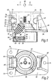
- Figure 1 shows a engine mount 30 comprising a dish-shaped metal plate 32 which is arranged to be bolted to the chassis or body of a vehicle by means of holes 34.
- a conically shaped resilient supporting element 36 defining a hollow working chamber 38 and preferably made of relatively stiff rubber carries a metal element 40 from which upstands a bolt 42 which, in use, is secured to the engine shown dotted at 44.
- the engine 44 is thus resiliently supported from the chassis or body of the vehicle by the rubber element 36.
- the working chamber has a base 39 connected to a compensation chamber 46 by a helical or circular channel of which part is shown at 48.
- the compensation chamber 46 is defined rigid metal plate 49 and by a flexible membrane 50 which is sealingly clamped around its periphery, as shown at 52, to the dish-shaped member 32.
- the chambers 38 and 46, and the connecting channel 48, are filled with hydraulic fluid. Vibration of the engine 44, in response to normal movement of the engine components and also in response to movement of the engine as a whole relative to the chassis or body of the vehicle following changes in engine torque or changes in the road contour, are partially absorbed by the rubber element 36.
- the corresponding oscillations of the rubber element 36 exert a pumping action on the hydraulic fluid in the working chamber 38, causing it to be pumped to and fro between that chamber and the compensation chamber 46 via the channel 48.
- the channel is designed to have a particular resonant frequency at which it exerts a damping effect on the oscillatory movement of the fluid, and thus helps to damp the vibrations of the engine.
- the chambers 38 and 46 can be interconnected via grills formed in the base 39 and in the plate 49, the holes in these grills opening into a chamber containing a disc-shaped flexible valve 54.
- Valve 54 vibrates in response to small amplitude, relatively high frequency, vibrations of the engine, thus interconnecting the chambers 38 and 46 for such vibrations and by-passing the channel 48.
- the movement of the valve element 54 is not sufficient to compensate for variation in volume of the working chamber and the main connection between the chambers 38 and 46 is via the channel 48.
- the engine is resiliently supported from the chassis or body of the vehicle but its vibrations are controllably damped.
- each abutment is generally cylindrical in shape.
- Each abutment is supported on a rigid bracket 64,66 which is mounted on and rigid with the mounting plate 32.
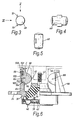
- the shape of the abutments 60,62 is shown more clearly in Figures 3,4 and 5.
- each abutment has a cylindrical body 68 integrally supporting two resilient ears 70,72.
- abutment 60 is mounted in position on the bracket 64 by means of the ears 70,72 which engage in slots 74,76 which are formed in metal clamps 77,78 which are in turn fixed to the bracket 64.
- the abutment 62 is mounted in similar fashion on the bracket 66 (but has been omitted from Figure 2 for clarity).
- the engine 44 is normally lightly in contact with the abutments 60,62 (though may be spaced slightly from them) in the normal position of the engine.
- the engine 44 In response to sudden and substantial movement of the engine relative to the chassis or body (such as for the reasons explained above), the engine 44 will move generally in the direction of the arrow A or the arrow B, and will thus compress the abutment 60 or the abutment 62 which accordingly and resiliently limits the movement of the engine to avoid damage and unnecessary mechanical contact and vibration.
- abutments shown in Figures 1 to 5 are thus advantageous over other abutments which are mounted on the chassis or body of the vehicle so as to be substantially incapable of any angular movement. Therefore, in response to a sudden movement of the engine relative to the chassis or body, such other abutments become subjected not only to a substantial compressive force but also to a substantial shear force because of the vertical component of the engine movement. Such abutments therefore become extremely stiff and transmit the vibratory movements of the engine to the chassis or body of the vehicle, which is contrary to the objectives of the abutments. These disadvantages are avoided by the abutments illustrated, because of their "rolling" capability.
- abutments 86 and 88 of non-cylindrical shape replace the cylindrical abutments 60 and 62 of Figures 1 and 2.
- Abutment 86 has a main body 90 of almost hemispherical shape with a pointed protruberance 92.
- the body 90 is integral with a base part 94 defining a small slot 96 and a larger slot 98.
- An overlapping extension 100 embraces the top of the bracket 64.
- the bracket 64 has a rigid element 102 secured to it.
- the abutment 86 is held in position by engagement of an ear 103 in a slot 104 (see also Figure 7) in the bracket 64 so that a further ear 105 compressingly engages the element 102.
- the size and depth of the slot 98 is such that the abutment 86 is capable of limited movement in the directions of the arrow E ( Figure 6).
- Abutment 88 is mounted in the same way as abutment 86.
- the abutments 86,88 are rendered capable of limited "rolling" movement, similar to that permitted to the abutments 60 and 62 in the embodiment of Figures 1 to 5. Again, therefore, the generation of significant shear force in the abutments, in response to eliptical movement of the engine, is substantially avoided.
- the overlapping lip 100 of the abutment 86 carries out the function of the stop 82 ( Figure 1).
- FIGS 8 and 9 show a modification of the arrangement of Figures 6 and 7.
- abutments 105 and 106 are used.
- Abutment 105 has a hemispherically shaped body 90 similar to the body 90 of the abutment 86 ( Figures 6 and 7).
- the abutment 105 differs from the abutments 86,88 in that it has a narrowed "waist" 108, with a base part 110 adhesively secured to a metal plate 112 which is clipped to the bracket 64 to support the abutment 105 in position.
- the abutment includes an overlapping lip part 114 performing the function of the stop 82 in Figure 1.
- Abutment 105 is similarly shaped and similarly mounted.
- the abutments 104 and 106 have narrowed waist portions 108, the abutments are given the limited "rolling" capability, similar to the abutments shown in the preceding Figures, again enabling them to accommodate the vertical components of the eliptical engine movement without generating substantial shear force in the abutments.
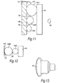
- an abutment arrangement comprises an abutment 120 of eliptical shape which is mounted on a part 124 of the body or chassis of the vehicle so as to be capable of limited "rolling" movement.
- Shown at 126 is part of the engine of the vehicle, or an arm rigidly attached to the engine.
- the abutment 20 has a small projecting horizontal lip 128 which makes contact with the arm 126. Lip 128 reduces the stiffness for low amplitude vibrations at engine idling speed. Because of the oval shape of the abutment 120 and its ability to "roll” in response to the eliptical movement of the arm 26 (as shown by the arrows 130), such the eliptical movement produces minimal shear force in the abutment.
- the abutment can have a strengthening embedded reinforcement 132 to adjust the horizontal stiffness without altering the vertical stiffness.
- Figure 11 shows an abutment arrangement incorporating three abutments 134A, 134B and 134C of progressively reducing diameter. They are connected together by integral flexible webs 136 and mounted in position on a bracket 138, connected to the chassis or body of the vehicle, by means of a web 140 and a fixing clip 142.
- the engine or an arm rigid with the engine is shown at 144. In the event of sudden and substantial movement of the engine, the arm 144 moves into contact with the abutment 134A. If the movement is sufficiently large, abutment 134A will be sufficiently compressed as to move the arm progressively into contact with the abutments 134B and 134C.
- abutments 134A,134B and 134C are each capable of limited “rolling" movement with respect to the bracket 138, so as to accommodate the eliptical movement of the engine (see arrows 145) without the creation of substantial shear force.
- Figures 12 and 13 show in elevation and plan view another abutment arrangement in which the abutment comprises a first cylindrical part 148A connected to a second cylindrical part 148B, of larger diameter, by means of a thin membrane 150.
- the abutment is mounted on a bracket 152, which is rigid with the chassis or body of the vehicle, by means of a belt 154 extending around the bracket 152.
- the engine, or an arm connected to it, is shown at 156. Because of the manner in which the abutment is mounted on the bracket 152 and because of the thin membrane 150, the abutment can undergo limited rolling movement in response to the eliptical movement of the engine.
- a spherical abutment 158 is mounted on a bracket 160, which is rigid with the chassis or body of the vehicle, by means of a stud 162. Again, the necessary rolling movement is permitted (and also movement in the other directions).
- an abutment 164 is mounted on a bracket 166 by means of a rubber belt 168 so as to be capable of limited rolling movement in response to contact with the engine (not shown).
- the abutment 164 is provided with a hole or hollow chamber 170 which provides initially increased flexibility and compressibility but which become more limited when the material of the abutment has been compressed sufficiently to close the hole or chamber 170.
- the abutment 170 shown in Figure 17 is generally cylindrical-shaped in cross-section (but can have another shape) and is mounted on a bracket 172 by rubber tabs 174,176 which are folded over the ends of the bracket 172.
- the flexibility of the rubber tabs 174,176 provides the necessary "rolling" capability for the abutment 170.
- the abutment 178 comprises a central part 180A of generally cylindrical shape in cross-section (but can have another shape) which is integrally joined to disc-shaped end parts 180B and 180C which have a greater diameter than the diameter of the main part 180A.
- the disc-shaped end parts 180B and 180C are permanently compressed, in a diametral direction, between a wall 182, forming part of the chassis or body of the vehicle, and an arm 184 which is rigid with the engine. In this way, the abutment 178 is mounted in position. Because the abutment 178 is held in position only by compression of the end parts 180B and 180C, it is thus capable of the required limited rolling movement.
- the abutment 120 shown in Figure 10 can be mounted in any of the ways described with reference to Figures 11,13,15,17 and 18.
- a rigid bracket 186 comprises a plate 188 rigidly attached to the chassis or body of the vehicle, and an upstanding leg 190.
- the leg 190 supports an annular-shaped abutment 192 by means of integral and flexible rubber arms 194.
- the annular abutment 192 is positioned within an annular space 196 defined by an annular wall 198 formed by means of a suitably shaped hole or recess in an arm 200 rigid with the engine.
- the annular abutment 192 can be interrupted around its periphery.
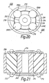
- an arm or pin 202 rigid with the engine, extends vertically upwards and nominally centrally of a circular hole or recess 204 defined by a ring 206 which is rigidly attached to the chassis or body of the vehicle.
- the abutment arrangement comprises spherical or cylindrical abutments 208A,208B,208C and 208D (or which have other revolutionary shape), which are mounted between the pin 202 and the wall 206 and supported in position by flexible and integral connecting webs 210.
- the eliptical movement of the engine is accommodated by the rolling movement of the abutments in the direction of the arrows X, the radial movement and vertical movement of light amplitude being restrained by compression of the abutments.
- bracket 186 could be connected to the engine, instead of to the chassis or body of the vehicle, and the arm 200 could be a wall defining a recess in the chassis or body.
- the arrangement of Figure 20 could be reversed so that the wall 206 is the wall of a hole or recess in the engine or an arm connected to the engine, and the pin 202 could be rigid with the chassis or body of the vehicle.
- Figure 21 shows an alternative way in which the abutments 208A,208B,208C and 208D can be connected to each other - by means of axial pins 212 and linking arms 214.
- abutment arrangements disclosed have been described as intended for limiting movement of the engine in a motor vehicle, they can be used for limiting movement of other resiliently supported components in a vehicle, such as the transmission or gearbox. They can also be used in other applications not involving motor vehicles.
Landscapes
- Engineering & Computer Science (AREA)
- General Engineering & Computer Science (AREA)
- Mechanical Engineering (AREA)
- Acoustics & Sound (AREA)
- Combustion & Propulsion (AREA)
- Physics & Mathematics (AREA)
- Chemical & Material Sciences (AREA)
- Aviation & Aerospace Engineering (AREA)
- Vibration Prevention Devices (AREA)
- Arrangement Or Mounting Of Propulsion Units For Vehicles (AREA)
- Professional, Industrial, Or Sporting Protective Garments (AREA)
- Accommodation For Nursing Or Treatment Tables (AREA)
- Surgical Instruments (AREA)
- Combined Devices Of Dampers And Springs (AREA)
Description
Claims (27)
- A movement-limiting abutment arrangement for resiliently limiting relative movement of first and second bodies (30,124,138,152,160,166,172,182,188,206;44,126, 144,156,184,200,202) towards each other, comprising abutment means (60,62,86,88,105,106,120,134,148,158,164,170,178,192,208) made of resilient material, and mounting means (64,66,94,96,98,112,140,154,162,168,174,176,180,194,210) for mounting the abutment means (60,62,86,88,105,106,120,134,148,158,164, 170,178,192,208) between the two bodies (30,124,138,152,160,166,172,182,188, 206;44,126,144,156,184,200,202) whereby relative movement of the two bodies (30,124,138,152,160,166,172,182,188,206;44,126,144,156,184,200,202) towards each other is resisted by contact with and compression of the resilient material, the mounting means (64,66,94,96,98,112,140,154,162,168,174,176,180,194,210) permitting the abutment means (60,62,86,88,105,106,120,134,148,158,164,170,178,192,208) to move to at least a limited extent in response to relative movement of the two bodies (30,124,138,152,160,166,172,182,188,206;44,126,144,156,184,200,202) in a direction transverse to their relative movement towards each other whereby to reduce the creation of a shear force in the resilient material in response to the transverse movement, characterised in that the mounting means (64,66,94,96,98,112,140, 154,162,168,174,176,180,194,210) mounts the abutment means (60,62,86,88,105,106, 120,134,148,158,164,170,178,192,208) for movement in the transverse direction by flexing of the resilient material.
- An abutment arrangement according to claim 1, characterised in that the abutment means (60,62,86,88,105,106,120,134,148,158,164,170,178,192,208) comprises a portion of the resilient material formed into predetermined shape, and in that the mounting means comprises flexible attachment means (64,66,94,96,98,112,140,154, 162,168,174,176,180,194,210).
- An abutment arrangement according to claim 1 or 2, characterised in that the mounting means (64,66,94,96,98,112,140,154,162,168,174,176,180,194,210) mounts the abutment means on one of the bodies (30,124,138,152,160,166,172,182,188, 206;44,126,144,156,184,200,202).
- An abutment arrangement according to any preceding claim, characterised in that the abutment means (60,62,86,88,105,106,120,134,148,158,164,170,178,192,208) presents at least one curved surface to at least one of the bodies (44,126,144,156,184,200,202).
- An abutment arrangement according to claim 4, characterised in that the abutment means (120,134,148,158,164,192,208) also presents a curved surface to the other body (30,124,138,152,160,166,172,182,188,206).
- An abutment arrangement according to claim 3 or 4, characterised in that the said transverse movement comprises movement of the said one body (44,126,144,156,184,200,202) in a direction generally tangential to and in contact with the curved surface.
- An abutment arrangement according to any one of claims 4 to 6, characterised in that the abutment means (134,208) is generally spherical.
- An abutment arrangement according to any one of claims 4 to 6, characterised in that the abutment means (60,62,148,164,170,178) is generally cylindrical.
- An abutment arrangement according to any one of claims 4 to 6, characterised in that the abutment means (120) is generally oval or eliptical.
- An abutment arrangement according to any preceding claim, characterised in that the abutment means (105,106,120) presents a protruberance extending towards one said body (44,126).
- An abutment arrangement according to any one of claims 1 to 6, characterised in that the abutment means comprises a plurality of individual abutments (134,148,208) each made of the resilient material.
- An abutment arrangement according to claim 11, characterised in that the abutments (134,148) are mounted adjacent to each other and have respectively differing cross-sectional sizes so as sequentially to be compressed by relative movement of the two bodies (30,124,138,152,160,166,172,182,188,206;44,126,144,156,184,200,202) towards each other.
- An abutment arrangement according to any one of claims 1 to 3, characterised in that the first body (44,202) is positioned within an area encompassed by the second body (30,206) so that the relative movement towards each other of the two bodies (44,202,30,206) comprises movement of the first body (44,202) towards a portion of the second body (30,206) and simultaneous movement of the first body (44,202) away from an opposite portion of the second body (30,206), and in that the abutment means comprises abutment means (60,62,86,88,192,208) positioned at locations spaced apart around the first body (44,202) and between it and the second body (30,206).
- An abutment arrangement according to claim 13, characterised in that the second body (206) extends annularly around the first body (202).
- An abutment arrangement according to claim 13 or 14, characterised in that the abutment means comprises individual abutments (60,62,86,88,208) each made of the resilient material.
- An abutment arrangement according to claim 15, characterised in that each of the abutments (60,62,86,88,208) is of spherical or cylindrical cross-section.
- An abutment arrangement according to claim 16, characterised in that the abutments (208) are flexibly linked together.
- An abutment arrangement according to claim 13, characterised in that the abutment means (192) extends continuously around the first body.
- An abutment arrangement according to claim 18, characterised in that the second body (206) extends annularly around the first body (202) and in that the abutment means (192) extends annularly around the first body (202) and between it and the second body (206).
- An abutment arrangement according to any preceding claim, characterised in that the abutment means (120) incorporates stiff reinforcement (132).
- An abutment arrangement according to any preceding claim, characterised in that the abutment means (164) includes a hollow space (170) for changing the initial compressibility of the abutment means (164).
- An abutment arrangement according to any preceding claim, characterised in that the abutment means (60,62,148,164,192) includes a flexible extension (70,72,150,154,168,194) and in which the mounting means comprises means for receiving and holding the flexible extension (70,72,150,154,168,194).
- An abutment arrangement according to any one of claims 1 to 21, characterised in that the mounting means comprises a flexible attachment to the abutment means.
- An abutment arrangement according to any one of claims 1 to 21, characterised in that the mounting means comprises means (94,96) for loosely and limitingly securing the abutment means (86,88).
- An abutment arrangement according to any one of claims 1 to 21, characterised in that the mounting means comprises securing means (180B,180C) made of resilient material attached to the abutment means (180A) but having a larger dimension than the abutment means (180A) in the direction of relative movement towards each other of the two bodies (182,184), whereby to be normally compressed between the two bodies (182,184) and thereby to support the abutment means (180A) therebetween.
- An abutment arrangement according to any preceding claim, characterised in that one of the bodies (30) is part of or is connected to the chassis or body of a vehicle and the other body (44) is part of or is connected to the engine thereof.
- An abutment arrangement according to claim 26, characterised in that it is in combination with an engine mount (30) for resiliently supporting the engine (44) from the chassis or body of the vehicle.
Priority Applications (1)
| Application Number | Priority Date | Filing Date | Title |
|---|---|---|---|
| DE29924354U DE29924354U1 (en) | 1998-07-08 | 1999-04-23 | Movement-limiting abutment arrangement for motor vehicle engine or other part |
Applications Claiming Priority (3)
| Application Number | Priority Date | Filing Date | Title |
|---|---|---|---|
| GB9814770A GB2339262B (en) | 1998-07-08 | 1998-07-08 | Movement-limiting abutment arrangements |
| GB9814770 | 1998-07-08 | ||
| PCT/GB1999/001274 WO2000003154A1 (en) | 1998-07-08 | 1999-04-23 | Movement-limiting abutment arrangements |
Publications (2)
| Publication Number | Publication Date |
|---|---|
| EP1095221A1 EP1095221A1 (en) | 2001-05-02 |
| EP1095221B1 true EP1095221B1 (en) | 2003-01-08 |
Family
ID=10835133
Family Applications (1)
| Application Number | Title | Priority Date | Filing Date |
|---|---|---|---|
| EP99918173A Expired - Lifetime EP1095221B1 (en) | 1998-07-08 | 1999-04-23 | Movement-limiting abutment arrangements |
Country Status (5)
| Country | Link |
|---|---|
| EP (1) | EP1095221B1 (en) |
| DE (1) | DE69904825T2 (en) |
| ES (1) | ES2191428T3 (en) |
| GB (1) | GB2339262B (en) |
| WO (1) | WO2000003154A1 (en) |
Families Citing this family (4)
| Publication number | Priority date | Publication date | Assignee | Title |
|---|---|---|---|---|
| GB0507094D0 (en) * | 2005-04-07 | 2005-05-11 | Avon Vibration Man Syst Ltd | Hydraulically damped mounting device |
| FR3079578B1 (en) * | 2018-04-03 | 2021-02-19 | Hutchinson | ANTI-VIBRATION DEVICE AND VEHICLE CONTAINING SUCH AN ANTI-VIBRATION DEVICE |
| DE102018117092B4 (en) * | 2018-07-16 | 2022-04-21 | Man Truck & Bus Se | Engine storage device |
| CN112303171B (en) * | 2019-07-31 | 2022-01-07 | 比亚迪股份有限公司 | Air spring and vehicle with same |
Family Cites Families (6)
| Publication number | Priority date | Publication date | Assignee | Title |
|---|---|---|---|---|
| US2697578A (en) * | 1951-05-04 | 1954-12-21 | Benjamin B Whittam | Vibration mounting |
| NL83462C (en) * | 1951-08-09 | |||
| GB978847A (en) * | 1963-12-05 | 1964-12-23 | Edge And Sons Ltd | Improvements in or relating to dock and like fenders |
| GB1073419A (en) * | 1964-12-18 | 1967-06-28 | Rita Margaret Hedges | Improvements in or relating to marine and inland water fenders |
| US4098211A (en) * | 1976-10-15 | 1978-07-04 | Regal Tool & Rubber Co., Inc. | Bumper rings |
| JPH06105096B2 (en) * | 1990-06-12 | 1994-12-21 | 東海ゴム工業株式会社 | Fluid-filled mount device and manufacturing method thereof |
-
1998
- 1998-07-08 GB GB9814770A patent/GB2339262B/en not_active Expired - Fee Related
-
1999
- 1999-04-23 DE DE69904825T patent/DE69904825T2/en not_active Expired - Fee Related
- 1999-04-23 EP EP99918173A patent/EP1095221B1/en not_active Expired - Lifetime
- 1999-04-23 WO PCT/GB1999/001274 patent/WO2000003154A1/en not_active Ceased
- 1999-04-23 ES ES99918173T patent/ES2191428T3/en not_active Expired - Lifetime
Also Published As
| Publication number | Publication date |
|---|---|
| DE69904825T2 (en) | 2003-09-11 |
| DE69904825D1 (en) | 2003-02-13 |
| GB2339262A (en) | 2000-01-19 |
| ES2191428T3 (en) | 2003-09-01 |
| GB2339262B (en) | 2002-06-12 |
| WO2000003154A1 (en) | 2000-01-20 |
| EP1095221A1 (en) | 2001-05-02 |
| GB9814770D0 (en) | 1998-09-09 |
Similar Documents
| Publication | Publication Date | Title |
|---|---|---|
| CA1301787C (en) | Fluid filled elastomeric damping device | |
| US5590733A (en) | Shock absorbing and sprung suspension system | |
| US4651980A (en) | Vibration isolator | |
| US4744547A (en) | Elastic engine mount | |
| US4607828A (en) | Hydraulic antivibration support | |
| US5213315A (en) | Method for varying the spring rigidity of an elastomer mount, and a corresponding mount | |
| US5782462A (en) | Hydraulically damped powertrain mount | |
| US5052510A (en) | Hybrid type vibration isolation apparatus | |
| US4378936A (en) | Engine mountings for trucks, motor coaches or the like utility vehicles | |
| JPH03223541A (en) | spring mount | |
| JPH02203037A (en) | Elastic base for material | |
| CA2247193A1 (en) | Vibration dampening assembly | |
| WO2000003154A1 (en) | Movement-limiting abutment arrangements | |
| US4881712A (en) | Hydraulic mount | |
| US20020180129A1 (en) | Hydraulically damped mounting device | |
| EP0907853B1 (en) | Resilient support | |
| EP0816734B1 (en) | Resilient support | |
| EP0728959B1 (en) | Vibration-damping link | |
| US4635747A (en) | Marine seismic vibrator having support structure including vibration isolators | |
| US6050554A (en) | Vibration damping assemblies | |
| US20080169592A1 (en) | Antivibration Support | |
| EP0792424A1 (en) | Mounting devices | |
| EP0926386A2 (en) | Hydroelastic supports | |
| GB2330892A (en) | Hydroelastic support | |
| EP0494217A1 (en) | Active accumulator vibration absorbing system |
Legal Events
| Date | Code | Title | Description |
|---|---|---|---|
| PUAI | Public reference made under article 153(3) epc to a published international application that has entered the european phase |
Free format text: ORIGINAL CODE: 0009012 |
|
| 17P | Request for examination filed |
Effective date: 20010130 |
|
| AK | Designated contracting states |
Kind code of ref document: A1 Designated state(s): DE ES FR IT |
|
| 17Q | First examination report despatched |
Effective date: 20011211 |
|
| GRAG | Despatch of communication of intention to grant |
Free format text: ORIGINAL CODE: EPIDOS AGRA |
|
| GRAG | Despatch of communication of intention to grant |
Free format text: ORIGINAL CODE: EPIDOS AGRA |
|
| GRAH | Despatch of communication of intention to grant a patent |
Free format text: ORIGINAL CODE: EPIDOS IGRA |
|
| GRAH | Despatch of communication of intention to grant a patent |
Free format text: ORIGINAL CODE: EPIDOS IGRA |
|
| GRAA | (expected) grant |
Free format text: ORIGINAL CODE: 0009210 |
|
| AK | Designated contracting states |
Kind code of ref document: B1 Designated state(s): DE ES FR IT |
|
| REF | Corresponds to: |
Ref document number: 69904825 Country of ref document: DE Date of ref document: 20030213 Kind code of ref document: P |
|
| ET | Fr: translation filed | ||
| REG | Reference to a national code |
Ref country code: ES Ref legal event code: FG2A Ref document number: 2191428 Country of ref document: ES Kind code of ref document: T3 |
|
| PLBE | No opposition filed within time limit |
Free format text: ORIGINAL CODE: 0009261 |
|
| 26N | No opposition filed |
Effective date: 20031009 |
|
| PGFP | Annual fee paid to national office [announced via postgrant information from national office to epo] |
Ref country code: IT Payment date: 20060430 Year of fee payment: 8 |
|
| PGFP | Annual fee paid to national office [announced via postgrant information from national office to epo] |
Ref country code: ES Payment date: 20070425 Year of fee payment: 9 |
|
| PGFP | Annual fee paid to national office [announced via postgrant information from national office to epo] |
Ref country code: DE Payment date: 20070430 Year of fee payment: 9 |
|
| PGFP | Annual fee paid to national office [announced via postgrant information from national office to epo] |
Ref country code: FR Payment date: 20070418 Year of fee payment: 9 |
|
| PG25 | Lapsed in a contracting state [announced via postgrant information from national office to epo] |
Ref country code: DE Free format text: LAPSE BECAUSE OF NON-PAYMENT OF DUE FEES Effective date: 20081101 |
|
| REG | Reference to a national code |
Ref country code: FR Ref legal event code: ST Effective date: 20081231 |
|
| PG25 | Lapsed in a contracting state [announced via postgrant information from national office to epo] |
Ref country code: FR Free format text: LAPSE BECAUSE OF NON-PAYMENT OF DUE FEES Effective date: 20080430 |
|
| REG | Reference to a national code |
Ref country code: ES Ref legal event code: FD2A Effective date: 20080424 |
|
| PG25 | Lapsed in a contracting state [announced via postgrant information from national office to epo] |
Ref country code: ES Free format text: LAPSE BECAUSE OF NON-PAYMENT OF DUE FEES Effective date: 20080424 |
|
| PG25 | Lapsed in a contracting state [announced via postgrant information from national office to epo] |
Ref country code: IT Free format text: LAPSE BECAUSE OF NON-PAYMENT OF DUE FEES Effective date: 20070423 |