EP1094639A2 - A communication controller and a communication method - Google Patents
A communication controller and a communication method Download PDFInfo
- Publication number
- EP1094639A2 EP1094639A2 EP00122163A EP00122163A EP1094639A2 EP 1094639 A2 EP1094639 A2 EP 1094639A2 EP 00122163 A EP00122163 A EP 00122163A EP 00122163 A EP00122163 A EP 00122163A EP 1094639 A2 EP1094639 A2 EP 1094639A2
- Authority
- EP
- European Patent Office
- Prior art keywords
- transmission
- priority
- abitration
- communication
- transmit data
- Prior art date
- Legal status (The legal status is an assumption and is not a legal conclusion. Google has not performed a legal analysis and makes no representation as to the accuracy of the status listed.)
- Withdrawn
Links
Images





Classifications
-
- H—ELECTRICITY
- H04—ELECTRIC COMMUNICATION TECHNIQUE
- H04L—TRANSMISSION OF DIGITAL INFORMATION, e.g. TELEGRAPHIC COMMUNICATION
- H04L12/00—Data switching networks
- H04L12/28—Data switching networks characterised by path configuration, e.g. LAN [Local Area Networks] or WAN [Wide Area Networks]
- H04L12/40—Bus networks
- H04L12/40006—Architecture of a communication node
- H04L12/40013—Details regarding a bus controller
-
- H—ELECTRICITY
- H04—ELECTRIC COMMUNICATION TECHNIQUE
- H04L—TRANSMISSION OF DIGITAL INFORMATION, e.g. TELEGRAPHIC COMMUNICATION
- H04L12/00—Data switching networks
- H04L12/28—Data switching networks characterised by path configuration, e.g. LAN [Local Area Networks] or WAN [Wide Area Networks]
- H04L12/40—Bus networks
- H04L12/407—Bus networks with decentralised control
- H04L12/413—Bus networks with decentralised control with random access, e.g. carrier-sense multiple-access with collision detection [CSMA-CD]
- H04L12/4135—Bus networks with decentralised control with random access, e.g. carrier-sense multiple-access with collision detection [CSMA-CD] using bit-wise arbitration
-
- H—ELECTRICITY
- H04—ELECTRIC COMMUNICATION TECHNIQUE
- H04L—TRANSMISSION OF DIGITAL INFORMATION, e.g. TELEGRAPHIC COMMUNICATION
- H04L12/00—Data switching networks
- H04L12/28—Data switching networks characterised by path configuration, e.g. LAN [Local Area Networks] or WAN [Wide Area Networks]
- H04L12/40—Bus networks
- H04L2012/40208—Bus networks characterized by the use of a particular bus standard
- H04L2012/40215—Controller Area Network CAN
-
- H—ELECTRICITY
- H04—ELECTRIC COMMUNICATION TECHNIQUE
- H04L—TRANSMISSION OF DIGITAL INFORMATION, e.g. TELEGRAPHIC COMMUNICATION
- H04L12/00—Data switching networks
- H04L12/28—Data switching networks characterised by path configuration, e.g. LAN [Local Area Networks] or WAN [Wide Area Networks]
- H04L12/40—Bus networks
- H04L2012/40267—Bus for use in transportation systems
- H04L2012/40273—Bus for use in transportation systems the transportation system being a vehicle
Definitions
- the present invention relates to a communication controller and a communication method, and in particular, to a communication controller and a communication method used in the CAN (Controller Area Network) communications.
- CAN Controller Area Network
- CAN communications use a protocol for serial communications whereby control is made so that contention in data transmission between a plurality of devices connected to the same bus line will not cause data corruption and only one device transmits data with the remaining devices waiting for the next transmission opportunity.
- Such a communication method may be used to connect engine controllers, brake controllers and various detectors in the field of automobile electrical equipment to perform real-time control of distributed devices efficiently and with high reliability.
- CAN communications is not limited to vehicles such as automobiles but is expandable to the field of industrial machinery such as intra-factory control systems, building maintenance, toys, and game machines.
- Fig. 8 is a schematic view of a configuration where a plurality of devices (hereinafter referred to as nodes) are connected to the bus line CBL for CAN communications, as an example of automobile electrical equipment system.
- a node ND1 represents a navigation system, a mode ND2 a CD (compact disc) player, a node ND3 a telephone controller, and nodes NDXs the remaining devices.
- Each node has a communication controller composed of IC chips and a CPU (microcomputer) for processing communications data and controlling the communication controller.
- the communication controller manages the output data output by the same controller and supervises the state of the bus line CBL.
- bus level the electric potential of a bus line (bus level) is divided into the dominant level (hereinafter referred to as the dominant) and the recessive level (hereinafter referred to as the recessive). Setting is made so that the dominant may overwrite the recessive, that is, the dominant may be prevalent.
- Fig. 9 shows a configuration for realizing such a setting.
- the bus line CBL operates in pairs with the ground line EL.
- a constant voltage is supplied to the bus line CBL from the constant voltage source PS.
- NPN transistors Q1 through Q3 To the bases of NPN transistors Q1 through Q3 are connected the outputs of the inverters IV1 to IV3. To the inputs of the inverters IV1 to IV3 are given transmit data T1 to T3 from nodes ND1 to ND3. The outputs of the drivers D1 to D3 are respectively given to the nodes ND1 to ND3 as receive data R1 to R3.
- Fig. 10 Relationship of the bus level to the transmit data T1 to T3 is shown in Fig. 10.
- Fig. 10 in case any one of the transmit data pieces T1 to T3 is given "0", the electric potential of the bus line goes dominant, and in case all of the transmit data pieces T1 to T3 is given "0", the electric potential of the bus line goes recessive.
- CAN communications use the data frame containing transmit data, the remote frame for requesting data transmission from other nodes via the bus line, the error frame used for reporting errors to other frames, and the overload frame for extending the time between data pieces or between remote frames.
- the data frame is composed of seven fields including the arbitration field, control field, and data field.
- the arbitration field has an SOF (Start of Frame) bit indicating the start of a frame, 11-bit or 29-bit identifier, and an RTR (Remote Transmission Request) bit for requesting data transmission.
- SOF Start of Frame
- RTR Remote Transmission Request
- the length of the data field is as short as a maximum of eight bytes (64 bits).
- Fig. 11 an example of data output from the two nodes (first node and second node) is shown as Fig. 11A and 11B, and the bus level state is shown as Fig. 11C. Note that Fig. 11 assumes a 11-bit identifier and the arbitration field is followed by the control field, which is followed by the data field.
- bit 10 to bit 4 contain the same data for the first and second nodes and the bus level contains the same data, although bit 3 is dominant for the first node and recessive for the second node, thus driving the bus level dominant.
- the controller of the second node recognizes the inconsistency between the bus level state and its own output data, and determines that it has lost in racing with the first node and suspends transmission and waits for the next transmission opportunity. As a result, only the first node can perform transmission and the bus level is the same as that of the first node.
- arbitration is made based on the contents of the arbitration field contained in the transmit data in each node to determine the node which is given priority in transmission.
- the node which has lost in arbitration suspends transmission so that data remains uncorrupted.
- the transmission abort is a feature whereby the transmission controller stops ongoing transmission in the event of contiguous losses in arbitration or contiguous transmission error, or receiving a transmission abort instruction from the CPU.
- Fig. 12 shows the basic flow of transmission abort.
- Fig. 12 in case transmission is made based on a transmission request (step ST1), normal completion of transmission terminates execution. In case an error occurs or the node loses in racing with other nodes because of a lower priority (step ST2), the CPU requests transmission abort (step ST3).
- the communication controller on receiving a transmission abort instruction, stops transmission.
- the controller checks that transmission is stopped (step ST4) then modifies the data in the identifier in the arbitration field (step ST5). Checkup in step ST5 is repeated until transmission is stopped.
- Modification to the identifier is such that single-bit recessive data is modified to dominant data for all identifier composed of 11 bits or 29 bits, on a per node basis and independently for each transmit data piece, without considering the priority of transmit data from another node.
- the identifier also contains data such as destination so that modification is limited.
- the communication controller performs transmission (step ST1) after upgrading the priority. In case transmission completes normally, execution terminates. In case an error occurs or the node loses again in racing with other nodes because of a lower priority (step ST2), step ST3 and the subsequent steps are repeated to upgrade the priority.
- elapsed time is measured via time measuring means such as a one-shot timer after the CPU has instructed the communication controller to output transmit data, and the CPU, assuming a loss in racing for transmission or an error in case completion of transmission is not reported even when a predetermined time has elapsed, issues a transmission abort request.
- the CPU must be equipped with a one-shot timer, etc. and must issue a transmission stop command as required, as well as a transmission instruction command.
- the invention proposed to solve the foregoing problems, aims at providing a communication controller which reduces the load on the CPU as a device in equalizing transmission opportunities and a communication method for equalizing transmission opportunities.
- a communication controller is a communication controller which is respectively included in each of a plurality of communication nodes connected to the bus line for CAN communications, receives transmit data from a microcomputer, and performs data transmission based on a transmission instruction from the microcomputer, the communication controller comprising a controller having a feature to output the transmit data to the bus line as well as to supervise the electric potential state of the bus line and determining an abitration loss in case the electric potential state of the bus line is different from the electric potential state assumed by the output data from the communication controller, and abitration loss counting means for measuring the abitration loss count, characterized in that the controller stops transmission in case the abitration loss count measured by the abitration loss counting means has reached a predetermined count.
- a communication controller further comprises a transmit data holding section for receiving the transmit data from the microcomputer and for temporarily holding the transmit data, the transmit data having a format where a part of the bit group of an identifier is modified to the priority-dedicated section for specifying the transmission priority, the transmit data holding section being configured so that data in the priority-dedicated section of the transmit data may be modified to upgrade the transmission priority by the microcomputer once the abitration loss count has reached the predetermined count and transmission is stopped.
- a communication controller is characterized in that the abitration loss counting means is a decremental counter whose predetermined count is set by the controller when it receives a transmission instruction from the microcomputer and which is decremented each time abitration loss is counted.
- a communication method is a communication method using the communication controller according to the first aspect of the invention, the method comprising a step (a) for performing data transmission toward the bus line based on a transmission request, a step (b) for determining win/lose of data transmission via supervision of the electric potential state of the bus line, and a step (c) for measuring the abitration loss count and stops transmission in case the abitration loss count has reached the predetermined count.
- a communication method is characterized in that the transmit data has a format where a part of the bit group of an identifier is modified to the priority-dedicated section for specifying the transmission priority, the method further comprising, after the step (c), a step (d) for modifying the priority-dedicated section of the transmit data in order to upgrade the transmission priority according to an instruction from the microcomputer, and a step (e) for modifying the priority-dedicated section in order to reset the transmission priority to the lowest level according to an instruction from the microcomputer.
- a communication method is characterized in that the bit length of the priority-dedicated section is set so that the maximum value of a numeral represented by the bit length can exceed the total number of the plurality of communication nodes.
- a communication method is characterized in that the elevation ratio of the transmission priority in the step (d) is the same between the plurality of communication nodes and the step (e) is executed in common between the plurality of communication nodes.
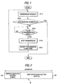
- step ST11 in case transmission is made based on a transmission request (step ST11), normal completion of transmission terminates execution.
- the communication controller counts the transmission losses (abitration loss count) and continues transmission until transmission from the node loses the predetermined count (in this example N times) (step ST13).
- the communication controller stops transmission (step ST14) and reports the transmission state to the CPU.
- the CPU modifies the transmission conditions, for example the identifier data in the arbitration field, the same as a conventional approach, in order to upgrade the priority (step ST15).
- the communication controller performs transmission based on a transmission request after the transmission conditions have been modified (step ST11). In case transmission completes normally, execution terminates. In case an error occurs or the node loses in racing with other nodes because of a lower priority (step ST12), step ST13 and the subsequent steps are repeated to further upgrade the priority.
- a communication controller has a feature to count transmission losses and configured to stop transmission and report to the CPU once the predetermined count is reached, and to modify the transmission conditions according to an instruction from the CPU.
- the CPU need not be equipped with a one-shot timer etc. to supervise the transmission state and need not issue a transmission stop instruction. This reduces the load on the CPU as a device.
- Fig. 2 is a schematic view of an identifier of the arbitration field to implement the communication method.
- part of the identifier ID bit group is turned into a priority-dedicated section PD to be used exclusively for priority control.
- the entire identifier is composed of 29 bits.
- the leading five bits are used as a priority-dedicated section PD and the remaining 24 bits as an arbitration data section AD having the same data as the conventional approach.
- the priority-dedicated section PD is composed of five bits in Fig. 2, the bit length is not limited to five bits but may be determined depending on the number of nodes and data types. Note that the communication method assumes that the value represented by the bit length of the priority-dedicated section PD be greater than the number of nodes to be connected to the bus line.
- 5-bit priority-dedicated section PD allows 32 steps of priority to be specified.
- an example of equalizing transmission opportunities will be discussed based on the 32-step priority.
- Fig. 3 is a schematic view of a state where transmission opportunities are equally given in the automobile electrical equipment system explained using Fig. 8.
- a node ND1 represents a navigation system, a mode ND2 a CD player, a node ND3 a telephone controller, and nodes NDXs the remaining devices.
- Priority specified in the priority-dedicated section starts from the lowest level 31 in any node.
- the arbitration data section AD specifies that priorities are given in the order of node number, that is, ND1, ND2, ND3, and NDX, in case the priority specified in the priority-dedicated section is identical.
- the communication controller stops transmission when it loses once in transmission.
- the CPU on receiving the report, operates to upgrade the priority specified in the priority-dedicated section.
- the CPU receives the report and resets the priority specified in the priority-dedicated section to the lowest priority level, that is, the CPU initializes the priority.
- numerals in each square represents a priority specified in the priority-dedicated section. From left to right in Fig. 3, the progress of the priority is shown which accompanies the passage of time in each node.
- the priority specified in the priority-dedicated section of transmit data in each node (hereinafter referred to as the first priority) is initially 31 without exception, which is the lowest level.
- transmission is made according to the priority specified in the arbitration data section (hereinafter referred to as the second priority).
- the second priority is a priority specific to each node which has been conventionally used.
- the node ND1 is the highest-priority node so that only the node ND1 performs transmission.
- the remaining nodes determine that they have lost in transmission as notified by their respective communication controllers, then reports to their respective CPUs.
- the CPUs upgrades the first priority by one step, to 30.
- the node ND1 which has succeeded in transmission is assigned the first priority level 31.
- the squares for successful nodes are marked with a circle ( ⁇ ).
- the nodes ND2 to NDX still have outstanding transmission requests.
- transmit data arbitration is made between the nodes ND2 to NDX.
- the first priority of the node ND1 is 31, which is lower than those of the remaining nodes.
- the second priority of transmit data in the node ND1 is, the node ND1 cannot transmit data. That is, the node ND1 cannot make an interrupt transmission.
- the corresponding priority is 31 and an interrupt transmission is not allowed.
- arbitration of transmit data is made based on the second priority of the nodes ND2 to NDX.
- the node ND2 is the highest-priority node so that only the node ND2 performs transmission.
- the nodes ND3 and NDX determine that they have lost in transmission as notified by their respective communication controllers, then reports to their respective CPUs.
- the CPUs upgrades the first priority by one step, to 29.
- the node ND1 has also lost in transmission so that the first priority is upgraded by one step, to 30.
- the node ND2 which has succeeded in transmission is assigned the first priority level 31 which is the lowest level.
- the nodes ND1, ND3 and NDX still have outstanding transmission requests.
- transmit data arbitration is made between the nodes ND1 to NDX.
- the first priority of the node ND1 is 30, and the first priority of the node ND2 is 31.
- arbitration of transmit data is made based on the second priority of the nodes ND3 and NDX.
- the node ND3 is the highest-priority node so that only the node ND3 performs transmission.
- the node NDX determines that it has lost in transmission as notified by its communication controller, then reports to its CPU.
- the CPU upgrades the first priority by one step, to 28.
- the nodes ND1 and ND2 have lost in transmission so that the first priority is upgraded by one step, to 29 and 30, respectively.
- the node ND3 which has succeeded in transmission is assigned the first priority level 31 which is the lowest level.
- the nodes ND1, ND2 and NDX still have outstanding transmission requests. In case a new transmission request takes place in the node ND3, transmit data arbitration is made between the nodes ND1 to NDX. In this practice, the first priority of the nodes ND1, ND2 and ND3 is 29, 30, and 31 respectively. Thus only the node NDX can perform transmission.
- the nodes ND1 and ND3 have lost in transmission so that the first priority is upgraded by one step, to 28, 29 and 30, respectively.
- the node NDX which has succeeded in transmission is assigned the first priority level 31 which is the lowest level.
- first priority for reflecting an abitration loss history in the transmit data from each node involved in transmission and upgrading in steps the first priority of a node which has losed in transmission in order to give the top priority to data which has failed to be transmitted most often while resetting the first priority of a node which has succeeded in transmission to the lowest level
- unequal transmission conditions can be eliminated such as the presence of a node which always loses in arbitration and a node which always wins in arbitration, thus reliably equalizing transmission opportunities.
- each communication controller is configured to stop transmission when it loses once in transmission, it is clear that this count may be more than once. That is, a communication controller configured to stop transmission when it loses N times running in transmission may perform transmission N times running in its turn, thus providing for repeated data transmissions.
- transmission ratio per node is constant. Transmission ratio may vary from node to node.
- the elevation ratio of the first priority may vary from node to node.
- a node may have the elevation ratio of the first priority in decrements of two steps or three steps, instead of one step (-1).
- Such a configuration can give different transmission ratios to nodes for unequal handling of nodes.
- this method does not fully equalize transmission opportunities, it does equalize transmission opportunities in a limited range.
- setting of the elevation ratio is limited by the maximum value of the numeral represented by the bit length of the priority-dedicated section PD. That is, the 2-step-based elevation ratio, in decrements of two steps (-2), means that the number of nodes has increased to 2. Unless the maximum value of the numeral represented by the bit length of the priority-dedicated section PD exceeds the number of all nodes plus 1, the aforementioned communication method is not functional. This means that setting of the elevation ratio is limited.
- Transmission ratio may be changed from node to node by changing the lowest level (initial value) of the first priority, not by changing the elevation ratio of the first priority.
- a smaller initial value means a smaller number of steps required until the right for transmission is acquired.
- a node having the initial value of the first priority smaller by n than one having the initial value can acquire the right for transmission once in (N-n) times. This means that N/(N-n) nodes have been added.
- setting of the initial value of the first priority is limited by the maximum value of the numeral represented by the bit length of the priority-dedicated section PD.
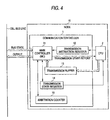
- a node 10 having a communication controller 1 and a CPU 2 is shown.
- the node 10 may further comprise a driver, etc. for supplying signals of a predetermined voltage. In a configuration not closely related to the invention, such a driver is omitted.
- the communications controller 1 outputs transmit data to the bus line CBL and comprises a main controller 11 for supervising the electric potential state of the bus line CBL, a transmission instruction register 12 whose output is connected to the main controller (abbreviated as MC) 11 for writing a transmission instruction from the CPU 2, a transmission buffer 13 whose output is connected to the MC 11 for writing transmit data from the CPU 2, a transmission state register 14 for reporting the transmission state from the MC 11 to the CPU 2, and an arbitration counter 15 (abitration loss counting means) connected to the MC 11 for counting the arbitration results or abitration loss count.
- MC main controller
- the arbitration counter 15 is configured by a decremental counter and configured to decrement a preset count by one each time transmission attempt fails.
- the arbitration counter 15 may be configured by an incremental counter.
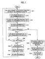
- the CPU 2 sets a priority in the bit position of the transmission buffer 13 corresponding to the priority-dedicated section PD of the identifier (hereinafter referred to as the priority-dedicated section PD of the buffer) explained using Fig. 2 (step ST21).
- Bit length of the priority-dedicated section is five bits and the priority is set to the lowest level as mentioned earlier.
- step ST22 the CPU 2 transfers the transmit data including data in the arbitration data section AD of the identifier shown in Fig. 2 to the transmission buffer 13 (step ST23).
- the CPU 2 gives a transmission instruction to the MC 11 by writing the transmission instruction to the transmission instruction register 12 (step ST24).
- This transmission instruction contains a transmission abort instruction for stopping transmission in case the communication controller has failed in transmission N times.
- the MC 11 on receiving the transmission instruction, sets the arbitration counter to N times (step ST25) and starts transmission (step ST26). At the same time, the MC 11 starts supervising the electric potential state of the bus line. The MC 11 reports start of transmission to the CPU 2.
- step ST 27 the MC 11 decrements the arbitration counter by one (step ST 28).
- step ST29 the MC 11 stops transmission (step ST30). In case arbitration counter has not reached zero, step ST 26 and the subsequent steps are repeated for transmission.
- the MC 11 reports abitration loss to the CPU 2 (step ST32) by writing abitration loss to the transmission state register 14 (step ST31).
- the CPU 2 recognizing the abitration loss, sets a new priority, that is, a higher priority in the priority-dedicated section of the transmission buffer 13 in step ST21 and repeats step 22 and the subsequent steps. For the second or subsequent transmission, the CPU 2 modifies the priority without transferring transmit data to the transmission buffer 13.
- Transmit data may be transferred to the transmission buffer 13 for the second or subsequent transmission.
- step ST27 the MC 11 reports transmission success to the CPU 2 (step ST34) by writing transmission success to the transmission state register 14 (step ST33).
- step ST35 the CPU 2 initializes the priority of the priority-dedicated section of the transmission buffer 13, that is, the CPU resets the priority to the lowest priority level to terminate transmission.
- the communication controller 1 comprises an arbitration counter 15 for counting the arbitration results or abitration loss count and after the predetermined abitration loss count has been reached, stops transmission and reports to the CPU, then modifies transmission conditions based on an instruction from the CPU 2.
- the CPU has only to issue a transmission instruction containing a transmission abort instruction for stopping transmission in case transmission has failed N times.
- the CPU need not be equipped with a one-shot timer etc. to supervise the transmission state. This reduces the load on the CPU 2 as a device.
- the communication method for reliably equalizing transmission opportunities explained using Fig. 3 may be implemented without using a communication controller according to the invention explained using Fig. 4.
- the communication method may be implemented without the communication controller being equipped with an arbitration counter, via a configuration where the CPU 2 comprises a one-shot timer, etc. to supervise the transmission state and issues a transmission abort instruction as required.
- Fig. 6 shows a block diagram of such a configuration.
- a node 10A comprising a communication controller 1A and a CPU 2A is shown.
- the configuration of the communication controller 1A is basically the same as that of the communication controller 1 in Fig. 4, except that the communication controller 1A does not comprise an arbitration counter 15 and the MC 11 does not have a feature to control the arbitration counter 15.
- the CPU 2A comprises a timer 21 which is set on receiving a transmission instruction and starts measuring the predetermined time, and has a feature to supervise the transmission state.
- the CPU 2 sets a priority in the priority-dedicated section of the transmission buffer 13 (step ST41).
- Bit length of the priority-dedicated section is five bits and the priority is set to the lowest level as mentioned earlier.
- the CPU 2A transfers the transmit data including data in the arbitration data section AD of the identifier shown in Fig. 2 to the transmission buffer 13 (step ST42).
- the CPU 2 gives a transmission instruction to the MC 11 by writing the transmission instruction to the transmission instruction register 12 (step ST24).
- the MC 11 on receiving a transmission instruction, starts transmission and supervision of the electric potential state of the bus line simultaneously (step ST44).
- the MC 11 reports start of transmission to the CPU 2A.
- step ST 45 the MC 11 reports abitration loss to the CPU 2A (step ST47) by writing abitration loss to the transmission state register 14 (step ST46).
- the CPU 2A which has recognized contiguous arbitration loss checks whether the predetermined time has elapsed on the timer 21 in step ST48. In case the predetermined time has not elapsed , the CPU 2A repeats step ST44 and the subsequent steps to continue transmission. Otherwise, the CPU 2A issues a transmission abort instruction to stop transmission (step ST49).
- the CPU 2A After stopping transmission, the CPU 2A sets a new priority ST49' or a higher priority in the priority-dedicated section of the transmission buffer 13 and repeats step ST42 and the subsequent steps. For retransmission, the CPU 2A modifies the priority without transferring transmit data to the transmission buffer 13.
- step ST45 the MC 11 reports transmission success to the CPU 2A (step ST51) by writing transmission success to the transmission state register 14 (step ST50).
- step ST52 the CPU 2A initializes the priority of the priority-dedicated section of the transmission buffer 13, that is, the CPU resets the priority to the lowest priority level to terminate transmission.
- the CPU 2A In the configuration of the communication controller 1A, the CPU 2A must be equipped with a one-shot timer, etc. to supervise the transmission state and the CPU 2A must issue a transmission stop instruction.
- the load on the CPU 2 as a device is not reduced but the same advantage as that from counting the losses in arbitration may be obtained by adjusting the set time of the timer 21, thus implementing the communication method for reliably equalizing transmission opportunities.
- a feature to count abitration loss is provided and transmission is stopped when the predetermined count is reached.
- a microcomputer need not be equipped with a one-shot timer, etc. to supervise the transmission state and the microcomputer need not issue a transmission stop instruction, thus reducing the load on the microcomputer as a device.
- the transmit data holding section is configured so that data in the priority-dedicated section of transmit data may be modified to upgrade the transmission priority by a microcomputer.
- abitration loss counting means is composed of a decremental counter, thus simplifying the device configuration.
- abitration loss is counted and transmission is stopped when the predetermined count is reached.
- a microcomputer need not supervise the transmission state and it need not issue a transmission stop instruction, thus reducing the load on the microcomputer as a device and providing more handy CAN communications.
- the priority-dedicated section of transmit data is modified to upgrade the transmission priority after the abitration loss count has reached a predetermined count and transmission has been stopped, as well as the priority-dedicated section of transmit data is modified to reset the transmission priority to the lowest level in step (b) in case successful transmission is assumed.
- a communication method for equalizing transmission opportunities can be operated normally.
- a communication method of the seventh aspect of the invention by specifying the same elevation ratio of the transmission priority between the plurality of communication nodes and operation for resetting the transmission priority to the lowest level is made in common between the plurality of communication nodes, transmission opportunities can be equalized in the simplest fashion.
Landscapes
- Engineering & Computer Science (AREA)
- Computer Networks & Wireless Communication (AREA)
- Signal Processing (AREA)
- Small-Scale Networks (AREA)
- Communication Control (AREA)
- Computer And Data Communications (AREA)
Abstract
Description
Claims (7)
- A communication controller respectively included in each of a plurality of communication nodes connected to a bus line for CAN communications, said communication controller receiving transmit data from a microcomputer and performing data transmission based on a transmission instruction from said microcomputer,said communication controller comprising:a controller having a feature to output the transmit data to said bus line as well as to supervise the electric potential state of said bus line and determining an abitration loss in case the electric potential state of said bus line is different from the electric potential state assumed by said output data from said communication controller, andabitration loss counting means for measuring the abitration loss count, whereinsaid controller stops transmission in case the abitration loss count measured by said abitration loss counting means reaches a predetermined count.
- The communication controller according to claim 1, further comprising:a transmit data holding section for receiving the transmit data from said microcomputer and for temporarily holding the transmit data,the transmit data having a format where a part of the bit group of an identifier is modified to priority-dedicated section for specifying the transmission priority,said transmit data holding section being configured so that data in said priority-dedicated section of the transmit data is modified to upgrade the transmission priority by said microcomputer once the abitration loss count reaches the predetermined count and transmission is stopped.
- The communication controller according to claim 2, whereinsaid abitration loss counting means is a decremental counter whose predetermined count is set by said controller when said controller receives a transmission instruction from said microcomputer and which is decremented each time abitration loss is counted.
- The communication method using the communication controller according to claim 1,
said method comprising:(a) a step for performing data transmission toward said bus line based on a transmission request,(b) a step for determining success/failure of data transmission via supervision of the electric potential state of said bus line, and(c) a step for measuring the abitration loss count and stops transmission in case said abitration loss count reaches the predetermined count. - The communication method according to claim 4, whereinsaid transmit data has a format where a part of the bit group of an identifier is modified to the priority-dedicated section for specifying the transmission priority,
said method further comprising: after said step (c),(d) a step for modifying said priority-dedicated section of the transmit data in order to upgrade the transmission priority according to an instruction from said microcomputer, and(e) a step for modifying said priority-dedicated section in order to reset the transmission priority to the lowest level according to an instruction from said microcomputer. - The communication method according to claim 5, whereinthe bit length of said priority-dedicated section is set so that the maximum value of a numeral represented by the bit length exceeds the total number of said plurality of communication nodes.
- The communication method according to claim 5, whereinthe elevation ratio of the transmission priority in the step (d) is the same between said plurality of communication nodes, andthe step (e) is executed in common between said plurality of communication nodes.
Applications Claiming Priority (2)
| Application Number | Priority Date | Filing Date | Title |
|---|---|---|---|
| JP29797999 | 1999-10-20 | ||
| JP29797999A JP2001119416A (en) | 1999-10-20 | 1999-10-20 | Communication control device and communication method |
Publications (2)
| Publication Number | Publication Date |
|---|---|
| EP1094639A2 true EP1094639A2 (en) | 2001-04-25 |
| EP1094639A3 EP1094639A3 (en) | 2001-12-05 |
Family
ID=17853579
Family Applications (1)
| Application Number | Title | Priority Date | Filing Date |
|---|---|---|---|
| EP00122163A Withdrawn EP1094639A3 (en) | 1999-10-20 | 2000-10-12 | A communication controller and a communication method |
Country Status (2)
| Country | Link |
|---|---|
| EP (1) | EP1094639A3 (en) |
| JP (1) | JP2001119416A (en) |
Cited By (5)
| Publication number | Priority date | Publication date | Assignee | Title |
|---|---|---|---|---|
| EP2852100A4 (en) * | 2012-05-14 | 2015-05-06 | Toyota Motor Co Ltd | DEVICE FOR MANAGING VEHICLE-SPECIFIC NETWORK COMMUNICATIONS AND COMMUNICATION MANAGEMENT METHOD |
| US9552180B2 (en) | 2014-03-19 | 2017-01-24 | Fuji Xerox Co., Ltd. | Information processing device, method and non-transitory computer-readable medium for selecting communication interface on basis of number of times communication interface request rejected |
| CN106850373A (en) * | 2017-02-24 | 2017-06-13 | 宁波工程学院 | Towards the non-demolition formula dynamically optimized scheduling method of CAN |
| US11063871B2 (en) | 2018-07-25 | 2021-07-13 | Toyota Jidosha Kabushiki Kaisha | Communication apparatus, communication method, non-transitory recording medium, and communication system |
| DE112016003908B4 (en) | 2015-08-31 | 2024-09-26 | Autonetworks Technologies, Ltd. | Communication device |
Families Citing this family (10)
| Publication number | Priority date | Publication date | Assignee | Title |
|---|---|---|---|---|
| JP2000209418A (en) * | 1999-01-11 | 2000-07-28 | Matsushita Electric Ind Co Ltd | Image communication device |
| JP2004048303A (en) | 2002-07-11 | 2004-02-12 | Yamaha Marine Co Ltd | Ship information communication device and information communication method |
| JP4033294B2 (en) | 2002-07-11 | 2008-01-16 | ヤマハマリン株式会社 | Data communication method in ship network |
| JP4127490B2 (en) | 2002-07-22 | 2008-07-30 | ヤマハマリン株式会社 | Ship engine starter |
| JP3967221B2 (en) | 2002-07-22 | 2007-08-29 | ヤマハマリン株式会社 | Ship propulsion control device |
| JP4232603B2 (en) | 2003-10-24 | 2009-03-04 | 富士ゼロックス株式会社 | Communication system, control device, CAN bus connection node, CAN bus communication method, and program |
| JP4839140B2 (en) * | 2006-06-23 | 2011-12-21 | 株式会社オートネットワーク技術研究所 | Relay connection unit |
| JP5098429B2 (en) * | 2007-05-11 | 2012-12-12 | トヨタ自動車株式会社 | Communications system |
| JP5147533B2 (en) * | 2008-05-20 | 2013-02-20 | 株式会社オートネットワーク技術研究所 | Relay device and relay method |
| JP6485338B2 (en) * | 2015-12-02 | 2019-03-20 | 株式会社デンソー | Communications system |
Family Cites Families (1)
| Publication number | Priority date | Publication date | Assignee | Title |
|---|---|---|---|---|
| US5854454A (en) * | 1996-09-16 | 1998-12-29 | Otis Elevator Company | Message routing in control area network (CAN) protocol |
-
1999
- 1999-10-20 JP JP29797999A patent/JP2001119416A/en active Pending
-
2000
- 2000-10-12 EP EP00122163A patent/EP1094639A3/en not_active Withdrawn
Cited By (6)
| Publication number | Priority date | Publication date | Assignee | Title |
|---|---|---|---|---|
| EP2852100A4 (en) * | 2012-05-14 | 2015-05-06 | Toyota Motor Co Ltd | DEVICE FOR MANAGING VEHICLE-SPECIFIC NETWORK COMMUNICATIONS AND COMMUNICATION MANAGEMENT METHOD |
| CN104272663B (en) * | 2012-05-14 | 2018-03-27 | 丰田自动车株式会社 | Communication management device and communication management method for vehicle network |
| US9552180B2 (en) | 2014-03-19 | 2017-01-24 | Fuji Xerox Co., Ltd. | Information processing device, method and non-transitory computer-readable medium for selecting communication interface on basis of number of times communication interface request rejected |
| DE112016003908B4 (en) | 2015-08-31 | 2024-09-26 | Autonetworks Technologies, Ltd. | Communication device |
| CN106850373A (en) * | 2017-02-24 | 2017-06-13 | 宁波工程学院 | Towards the non-demolition formula dynamically optimized scheduling method of CAN |
| US11063871B2 (en) | 2018-07-25 | 2021-07-13 | Toyota Jidosha Kabushiki Kaisha | Communication apparatus, communication method, non-transitory recording medium, and communication system |
Also Published As
| Publication number | Publication date |
|---|---|
| JP2001119416A (en) | 2001-04-27 |
| EP1094639A3 (en) | 2001-12-05 |
Similar Documents
| Publication | Publication Date | Title |
|---|---|---|
| US5600782A (en) | Can interface with enhanced fault confinement | |
| US10606796B2 (en) | On-board network system, communication control method in the on-board network system, and on-board gateway | |
| US4590468A (en) | Token access controller protocol and architecture | |
| JP3115322B2 (en) | How the message is formed | |
| KR100233180B1 (en) | Communication systems | |
| JP3671057B2 (en) | Method and apparatus for automatic retransmission of packets in a network adapter | |
| US20070140294A1 (en) | Communication message conversion apparatus and communication message conversion method | |
| JP2001119416A (en) | Communication control device and communication method | |
| JP3829679B2 (en) | Communication control device | |
| JPH02246444A (en) | Data transmission method and system | |
| JP3770053B2 (en) | Method for determining communication return in vehicle network | |
| EP0880251B1 (en) | Multiplex transmission system | |
| JP5147533B2 (en) | Relay device and relay method | |
| JP3106927B2 (en) | Communications system | |
| US7283553B2 (en) | Data relay device and multiplex communication system | |
| US5666485A (en) | Software driver for a system bus | |
| JP2004519059A (en) | How to drive distributed safety critical system components | |
| CN110554984B (en) | CPLD-based serial port bridging method and system | |
| JP2001325212A (en) | Method and device for transmitting data block from source processor to destination processor in multiprocessor system | |
| US12493575B2 (en) | Backoff timer for in-band interrupt on an I3C bus | |
| JP2000267982A (en) | Information processor | |
| JPH08223190A (en) | Communication system | |
| JP2006237832A (en) | Communication node failure detection apparatus and method | |
| JP4361540B2 (en) | Gateway device, data transfer method, and program | |
| JP2001177542A (en) | Communication device between control nodes |
Legal Events
| Date | Code | Title | Description |
|---|---|---|---|
| PUAI | Public reference made under article 153(3) epc to a published international application that has entered the european phase |
Free format text: ORIGINAL CODE: 0009012 |
|
| AK | Designated contracting states |
Kind code of ref document: A2 Designated state(s): AT BE CH CY DE DK ES FI FR GB GR IE IT LI LU MC NL PT SE |
|
| AX | Request for extension of the european patent |
Free format text: AL;LT;LV;MK;RO;SI |
|
| PUAL | Search report despatched |
Free format text: ORIGINAL CODE: 0009013 |
|
| AK | Designated contracting states |
Kind code of ref document: A3 Designated state(s): AT BE CH CY DE DK ES FI FR GB GR IE IT LI LU MC NL PT SE |
|
| AX | Request for extension of the european patent |
Free format text: AL;LT;LV;MK;RO;SI |
|
| AKX | Designation fees paid | ||
| REG | Reference to a national code |
Ref country code: DE Ref legal event code: 8566 |
|
| RAP1 | Party data changed (applicant data changed or rights of an application transferred) |
Owner name: SUMITOMO WIRING SYSTEMS, LTD. Owner name: SUMITOMO ELECTRIC INDUSTRIES, LTD. Owner name: AUTONETWORKS TECHNOLOGIES, LTD. |
|
| STAA | Information on the status of an ep patent application or granted ep patent |
Free format text: STATUS: THE APPLICATION IS DEEMED TO BE WITHDRAWN |
|
| 18D | Application deemed to be withdrawn |
Effective date: 20020606 |