EP1093543B1 - Flexible armature for fuel injection system control valve - Google Patents
Flexible armature for fuel injection system control valve Download PDFInfo
- Publication number
- EP1093543B1 EP1093543B1 EP99930681.4A EP99930681A EP1093543B1 EP 1093543 B1 EP1093543 B1 EP 1093543B1 EP 99930681 A EP99930681 A EP 99930681A EP 1093543 B1 EP1093543 B1 EP 1093543B1
- Authority
- EP
- European Patent Office
- Prior art keywords
- armature
- control valve
- body portion
- valve
- fuel
- Prior art date
- Legal status (The legal status is an assumption and is not a legal conclusion. Google has not performed a legal analysis and makes no representation as to the accuracy of the status listed.)
- Expired - Lifetime
Links
- 239000000446 fuel Substances 0.000 title claims description 55
- 238000002347 injection Methods 0.000 title claims description 10
- 239000007924 injection Substances 0.000 title claims description 10
- 238000005086 pumping Methods 0.000 claims description 24
- 239000012530 fluid Substances 0.000 claims description 3
- 125000006850 spacer group Chemical group 0.000 description 6
- 238000004891 communication Methods 0.000 description 4
- 230000000712 assembly Effects 0.000 description 3
- 238000000429 assembly Methods 0.000 description 3
- 238000002485 combustion reaction Methods 0.000 description 3
- 238000013016 damping Methods 0.000 description 2
- 238000000034 method Methods 0.000 description 2
- 239000002283 diesel fuel Substances 0.000 description 1
- 230000003467 diminishing effect Effects 0.000 description 1
- 230000003628 erosive effect Effects 0.000 description 1
- 238000004519 manufacturing process Methods 0.000 description 1
- 230000008707 rearrangement Effects 0.000 description 1
Images



Classifications
-
- F—MECHANICAL ENGINEERING; LIGHTING; HEATING; WEAPONS; BLASTING
- F02—COMBUSTION ENGINES; HOT-GAS OR COMBUSTION-PRODUCT ENGINE PLANTS
- F02M—SUPPLYING COMBUSTION ENGINES IN GENERAL WITH COMBUSTIBLE MIXTURES OR CONSTITUENTS THEREOF
- F02M59/00—Pumps specially adapted for fuel-injection and not provided for in groups F02M39/00 -F02M57/00, e.g. rotary cylinder-block type of pumps
- F02M59/20—Varying fuel delivery in quantity or timing
- F02M59/36—Varying fuel delivery in quantity or timing by variably-timed valves controlling fuel passages to pumping elements or overflow passages
- F02M59/366—Valves being actuated electrically
-
- F—MECHANICAL ENGINEERING; LIGHTING; HEATING; WEAPONS; BLASTING
- F02—COMBUSTION ENGINES; HOT-GAS OR COMBUSTION-PRODUCT ENGINE PLANTS
- F02M—SUPPLYING COMBUSTION ENGINES IN GENERAL WITH COMBUSTIBLE MIXTURES OR CONSTITUENTS THEREOF
- F02M57/00—Fuel-injectors combined or associated with other devices
- F02M57/02—Injectors structurally combined with fuel-injection pumps
-
- F—MECHANICAL ENGINEERING; LIGHTING; HEATING; WEAPONS; BLASTING
- F02—COMBUSTION ENGINES; HOT-GAS OR COMBUSTION-PRODUCT ENGINE PLANTS
- F02M—SUPPLYING COMBUSTION ENGINES IN GENERAL WITH COMBUSTIBLE MIXTURES OR CONSTITUENTS THEREOF
- F02M59/00—Pumps specially adapted for fuel-injection and not provided for in groups F02M39/00 -F02M57/00, e.g. rotary cylinder-block type of pumps
- F02M59/44—Details, components parts, or accessories not provided for in, or of interest apart from, the apparatus of groups F02M59/02 - F02M59/42; Pumps having transducers, e.g. to measure displacement of pump rack or piston
- F02M59/46—Valves
- F02M59/466—Electrically operated valves, e.g. using electromagnetic or piezoelectric operating means
-
- F—MECHANICAL ENGINEERING; LIGHTING; HEATING; WEAPONS; BLASTING
- F02—COMBUSTION ENGINES; HOT-GAS OR COMBUSTION-PRODUCT ENGINE PLANTS
- F02M—SUPPLYING COMBUSTION ENGINES IN GENERAL WITH COMBUSTIBLE MIXTURES OR CONSTITUENTS THEREOF
- F02M2200/00—Details of fuel-injection apparatus, not otherwise provided for
- F02M2200/04—Fuel-injection apparatus having means for avoiding effect of cavitation, e.g. erosion
Definitions
- This invention relates to a control valve assembly for damping control valve motion in a heavy duty truck diesel fuel injection system.
- Fuel control valve assemblies in vehicular fuel injection systems typically include a housing having a control valve chamber, a control valve having a piston valve body, and a valve stop.
- Electromagnetic actuators are commonly used in control valve assemblies for electronically controlling actuation of the control valve.
- the electromagnetic actuator usually a solenoid, is enclosed in a stator.
- the control valve is rigidly secured to an armature.
- a spring is used to urge the control valve toward a deactuated position which places the armature a short distance away from the stator, and which is usually the open position for the control valve.
- the solenoid When the solenoid is energized, the armature is pulled up against the stator, against the spring bias, moving the control valve to the actuated position which is usually the closed position for the control valve.
- the electromagnetically actuated valve allows greater sophisticated and more precise control over the injection process, thereby improving combustion.
- control valve bounce limits the ability to control the combustion process in these existing pumps and injectors.
- Control valve bounce occurs when the armature is pulled up against the stator by the energized solenoid, and the armature bounces upon impact with the stator.
- the bouncing armature causes the control valve, which is rigidly secured to the control valve, to bounce in diminishing series fashion before finally seating. This control valve bounce can significantly lessen the precision of the fuel flow process, and thereby lessen the combustion efficiency.
- US Patent Number 3592392 and Japanese Patent Publication JP 09273460 disclose fuel injector assemblies with armatures which have grooves formed in them. These grooves are formed partway through the armature and are configured simply to reduce eddy currents. These rearrangements do not address the problem of valve bounce.
- US Patent, Number 5636615 describes a fuel pump having an armature having fuel flow ports which allow fuel to flow from one side of the armature to another. This arrangement prevents cavitation erosion of the armature, but does not address the problem of valve bounce when the armature contacts the stator.
- a pump for a fuel injection system comprises a pump body having a pumping chamber, a fuel inlet for supplying fuel to the pumping chamber, an outlet port, and a control valve chamber between the pumping chamber and the outlet port.
- a plunger is disposed in the pumping chamber.
- An actuatable control valve disposed in the control valve chamber controls fuel.
- the control valve includes a valve body moveable between actuated and deactuated positions.
- the pump further comprises a stator assembly including an actuator operable to actuate the control valve, and an armature.
- the armature has a middle beam portion connected to an outer body portion.
- the control valve is secured to the middle beam portion.
- the control valve and the armature are arranged such that operation of the actuator causes the armature to urge the valve body toward the actuated position.
- the armature has at least one through slot formed at the interface of the middle beam portion and the outer body portion.
- the through-slot extends through the armature.
- the at least one slot is configured to allow the armature to flex, and specifically allows the middle beam portion to flex and move relative to the outer body portion, during actuation of the control valve.
- the armature flexes to damp movement of the valve body relative to the armature outer body portion as the valve body moves to the actuated position. That is, any bouncing of the armature outer body is dumped by the flexing armature, reducing any resulting bouncing of the control valve.
- the at least one slot includes a pair of parallel slots located on opposite sides of the armature middle beam portion.
- the control valve is secured to the armature between the pair of slots..
- the armature middle beam portion has a first thickness that is less than a second thickness of the armature outer body portion. Still further, the armature middle beam portion preferably has at least one hole extending therethrough. The hole extends perpendicular to a face of the armature.
- a fuel injector comprises an injector body with a pumping chamber and a control valve chamber, a plunger, an actuatable control valve, and a stator assembly including an actuator.
- the injector further comprises an armature having a middle beam portion connected to an outer body portion.
- the control valve is secured to the middle beam portion; and, the control valve and the armature are arranged such that operation of the actuator causes the armature to urge the valve body toward the actuated position.
- the armature has at least one slot formed at the interface of the middle beam portion and the outer body portion.
- the at least one slot is configured to allow the armature to flex during actuation of the control valve.
- the armature flexes to damp movement of the valve body relative to the armature outer body portion as the valve body moves to the actuated position that is, any bouncing of the armature outer body is dumped by the flexing armature, reducing any resulting bounce of the control valve.
- a component for use in a control valve assembly in a fuel injection system comprises an armature having a middle beam portion connected to an outer body portion.
- the middle beam portion is adapted to secure to an actuable control valve.
- the armature has at least one slot formed at the interface of the middle beam portion and the outer body portion.
- the at least one slot is configured to allow the armature to flex during actuation of the control valve to damp movement of the control valve relative to the armature outer body portion as the control valve moves to the actuated position. That is, any bouncing of the armature outer body is dumped by the flexing armature, reducing any resulting bounce of the control valve.
- armatures made in accordance with the present invention for pumps or injectors may be manufactured as a one-piece armature.
- the use of a one-piece armature design reduces manufacturing expense, while providing a component that damps control valve bounce when the valve body seats in the actuated position.
- a pump 10 made in accordance with the present invention is illustrated.
- the pump 10 has a pump body 12 with a pump body end portion 14.
- a pumping chamber 16 is defined by pump body 12.
- a fuel inlet 18 for supplying fuel to pumping chamber 16 is located on the periphery of pump body 12.
- Pump body 12 further has an outlet port 20, and a control valve chamber 22 between pumping chamber 16 and outlet port 20.
- O-rings 24 are provided to seal fuel inlet 18 with respect to an engine block which receives pump 10.
- Passageways 26 and 28 connect outlet port 20, control valve chamber 22, and pumping chamber 16.
- a reciprocating plunger 30 is disposed in pumping chamber 16.
- Plunger 30 has a head end 32 and a tail end 34.
- Plunger 30 is reciprocatable over a stroke range between a retracted position indicated at 30 and an extended position indicated in phantom at 31.
- a plunger spring 40 resiliently biases plunger 30 to the retracted position 31.
- a stator assembly 42 contains an electromagnetic actuator 44, such as a solenoid, and has terminals for connecting to a power source to provide power for electromagnetic actuator 44.
- An electromagnetically actuated control valve 46 is disposed in control valve chamber 22 for controlling fuel.
- Control valve 46 includes a piston valve body 48.
- Piston valve body 48 is movable between a deactuated position and an actuated position within control valve chamber 22. Typically, the deactuated position is the open position, and the actuated position is the closed position for valve body 48.
- An annular fuel filter 50 is disposed in pump body 12 about a central axis of piston valve body 48. Fuel inlet 18 allows fuel to pass through fuel filter 50 prior to entering pumping chamber 16.
- An armature 52 is secured to control valve 46 by a fastener such as a screw 54.
- a valve stop 60 is disposed in pump body 12 adjacent to control valve chamber 22.
- a control valve spring 70 resiliently biases piston valve body 48 into the deactuated position.
- a control valve spring seat 72 and a control valve spring retainer 76 abut first and second ends 74 and 78 of control valve spring 70, respectively.
- a stator spacer 80 having a central opening 82 for receiving armature 52 therein is disposed between pump body 12 and stator assembly 42.
- Stator spacer 80 has notches 81 for receiving retainer 76.
- O-rings 84 and 85 seal stator spacer 80 against stator assembly 42 and pump body 12, respectively.
- Stop plate 62 has holes 86 in alignment with holes 87 in pump bods 12, and holes 88 and 89 in stator assembly 42 and stator spacer 80, respectively.
- Fasteners 90 extend through stator assembly 42, stator spacer 80, and pump body 12. Fasteners 90 secure stop plate 62 against valve stop 60.
- washers 92 are used with fasteners 90, and a nameplate 93 may be secured to stator assembly 42 for identification purposes.
- Cam follower assembly 100 has a housing 102 with an elongated slot 104.
- Cam follower assembly 100 has an axle 106 and a roller 108 for engagement with a camshaft (not shown).
- Plunger 30 is reciprocated within pumping chamber 16 between the extended position 31 and the retracted position 30 by cam follower assembly 100.
- a cylindrical sleeve 110 has an aperture 112 in communication with elongated slot 104.
- Cylindrical sleeve 110 has first and second end portions 114 and 116, respectively.
- Pump body end portion 14 interfits with first end portion 114 of cylindrical sleeve 110.
- Second end portion 116 of cylindrical sleeve 110 relatively reciprocatably interfits with cam follower assembly 100 for allowing cam follower assembly 100 to drive plunger 30.
- Cam follower assembly 100 reciprocates within cylindrical sleeve 110 and drives plunger 30 relative to cylindrical sleeve 110 over the stroke range.
- a retainer guide 120 extends through aperture 112, cylindrical sleeve 110, and engages slots 104 in cam follower assembly 100.
- a clip 122 retains guide 120 within aperture 112.
- a plunger spring seat 130 is received in housing 102 of cam follower assembly 100. Plunger spring seat 130 abuts a first end 132 of plunger spring 40. Pump body end portion 14 abuts second end 134 of plunger spring 40.
- Pump body 12 has a first annulus 150 in communication with fuel inlet 18 for supplying fuel to the pumping chamber 16. Pump body 12 further has a second annulus 152 in communication with pumping chamber 16 for receiving excess fuel therefrom.
- An annular belt 154 separates first and second annuli 150 and 152, respectively.
- An excess fuel chamber 158 receives excess fuel from control valve chamber 22.
- a conventional fuel equalizing passage 161 provides fuel communication between excess fuel chambers 158 and the control valve and spring chambers.
- a return passageway 160 connects excess fuel chamber 158 to second annulus 152.
- Another return passageway 162 connects pumping chamber 16 to second annulus 152 for receiving any fuel that leaks between plunger 30 and pump body 12.
- Second annulus 152 is defined by annular belt 154 and first end portion 114 of cylindrical sleeve 110.
- fuel is supplied to pump 10 through internal fuel passageways in the engine block (not shown).
- piston valve body 48 is shown in the unactuated position. Upon actuation, piston valve body 48 is urged inwardly from the open position against valve stop 60 (not specifically shown) to the closed position depicted in FIG. 2 . Fuel is allowed to flow through passageway 26 in pump body 12 toward outlet port 20 in accordance with control valve 46 being opened and closed in a fixed sequence allowing the desired fuel pressure to be developed while closed. Passageway 26 is always open to the pumping chamber but fuel flow to the nozzle is precluded, as described, and optionally with the assist of a pressure relief valve (not shown) within the high pressure line, pursuant to conventional practice.
- embodiments of the present invention may alternatively be configured with as inwardly opening control valve, as opposed to the inwardly closing design depicted in FIG. 1 . That is, flex armatures of the present invention dump valve bounce that occurs when the armature is pulled to the stator by the energized solenoid. As such, the control valve may be configured to be either opened or closed in the actuated position, with the flex armature damping valve bounce as the valve seats in its actuated position.
- armature 52 is secured to control valve 46 by screw 54.
- Fuel is received from a fuel supply by first annulus 150 and supplied to fuel inlet 18.
- Fuel inlet 18 routes fuel through fuel filter 50 and to pumping chamber 16.
- the camshaft (not shown) drives cam follower assembly 100.
- Plunger 30 is moved from the retracted position 30 to the extended position 31, and fuel is pressurized within pumping chamber 16 when control valve 46 is held closed.
- Armature 52 flexes upon control valve actuation to damp control valve bounce during valve closing, or in the alternative, during valve opening (not specifically illustrated).
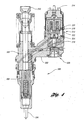
- injector 200 made in accordance with the present invention is illustrated.
- Injector 200 has an injector body 202 and a nozzle assembly 204.
- Spring cage assembly 206 is located adjacent nozzle assembly 204.
- a plunger 208 is reciprocatably driven within body 202 by a push rod 210.
- a stator 214 includes an actuator for controlling an electronically controlled valve assembly 212.
- a flex armature 216 of the present invention is secured to a control valve 218 by an armature screw 220. Armature 216 is encircled by a stator spacer 222. Control valve 218 is biased toward a deactuated position by control valve spring 224.
- armature 216 Upon actuation, armature 216 is pulled toward stator 214 resulting in control valve 218 moving against the bias of spring 224 into the actuated position. Armature 216 flexes to damp control valve bounce when control 218 moves into an seats in the actuated position.
- Injector 200 operates in a known manner, as shown, for example, in U.S. Patent No. 4,618,095 , assigned to the assignee of the present invention, and hereby incorporated by reference in its entirety. Similar to pump 10 ( FIG. 1 ), control valve assembly 212 may be configured to either open or close upon valve actuation, based on the particular pump or injector design.
- Flex armature 52 of pump 10 ( FIG. 1 ), and flex armature 216 of injector 200 ( FIG. 4 ), are configured in accordance with the present invention to damp valve bounce during valve actuation.
- a preferred embodiment of a flex armature of the present invention is depicted in FIGS. 5-11 , where the armature is generally indicated at 230.
- armature 230 has a middle beam portion 232 connected to an outer body portion 234.
- Armature 230 has at least one slot 236, and preferably a pair of parallel slots 236, formed at the interface of middle beam portion 232 and outer body portion 234.
- the pair of parallel slots 236 are located on opposite sides of armature middle beam portion 232.
- the at least one slot, but preferably pair of parallel slots 236, are configured to allow armature 230 to flex during actuation of the control valve.
- the control valve is secured to middle beam portion 232, as shown in pump 10 ( FIGS. 1, 3 ) and injector 200 ( FIG. 4 ). Operation of the actuator causes armature 230 to urge the control valve toward the actuated position, by pulling armature 230 toward the stator.
- the forces on armature 230 act primarily on outer body portion 234, allowing middle beam portion 232 to flex during actuation of the control valve. Thus, movement of the control valve relative to armature outer body portion 234 is damped as the control valve moves to the actuated position.
- armature middle beam portion 232 has a first thickness that is less than a second thickness of armature outer body portion 234, as best shown in FIG. 6 . Substantially all of middle beam portion 232 is thin with the exception of the point of attachment to the control valve. The thinned middle beam portion 232 facilitates flexing of armature 230.
- armature middle beam portion 232 has at least one whole, and preferably a pair of holes 238 extending perpendicular to a face of the armature. Holes 238 allow fluid flow therethrough when armature 230 is immersed in a fluid filled chamber. Holes 238 have been found to help reduce cavitation of armature 230.
- middle beam portion 232 and outer body portion 234 interfacing each other with at least one slot that allow armature 230 to flex.
- the flexing armature is constructed to damp any bouncing of armature outer body 234, reducing any resulting bounce of the control valve.
- the flex armature isolates the movement of the control valve from the armature by the flexible beam that has been cut in the middle of the armature. Attaching the valve to the middle of the beam helps minimize valve bounce created when the control valve is closed (in an inwardly closing configuration) by the armature being pulled to the stator.
Landscapes
- Engineering & Computer Science (AREA)
- Chemical & Material Sciences (AREA)
- Combustion & Propulsion (AREA)
- Mechanical Engineering (AREA)
- General Engineering & Computer Science (AREA)
- Physics & Mathematics (AREA)
- Electromagnetism (AREA)
- Fuel-Injection Apparatus (AREA)
- Electrically Driven Valve-Operating Means (AREA)
Description
- This invention relates to a control valve assembly for damping control valve motion in a heavy duty truck diesel fuel injection system.
- Fuel control valve assemblies in vehicular fuel injection systems typically include a housing having a control valve chamber, a control valve having a piston valve body, and a valve stop. Electromagnetic actuators are commonly used in control valve assemblies for electronically controlling actuation of the control valve. The electromagnetic actuator, usually a solenoid, is enclosed in a stator. The control valve is rigidly secured to an armature. A spring is used to urge the control valve toward a deactuated position which places the armature a short distance away from the stator, and which is usually the open position for the control valve. When the solenoid is energized, the armature is pulled up against the stator, against the spring bias, moving the control valve to the actuated position which is usually the closed position for the control valve. The electromagnetically actuated valve allows greater sophisticated and more precise control over the injection process, thereby improving combustion.
- Although fuel pumps and injectors having electromagnetically actuated control valves have been used in many applications that have been commercially successful, control valve bounce limits the ability to control the combustion process in these existing pumps and injectors. Control valve bounce occurs when the armature is pulled up against the stator by the energized solenoid, and the armature bounces upon impact with the stator. The bouncing armature causes the control valve, which is rigidly secured to the control valve, to bounce in diminishing series fashion before finally seating. This control valve bounce can significantly lessen the precision of the fuel flow process, and thereby lessen the combustion efficiency.
-
US Patent Number 3592392 and Japanese Patent PublicationJP 09273460 -
US Patent, Number 5636615 describes a fuel pump having an armature having fuel flow ports which allow fuel to flow from one side of the armature to another. This arrangement prevents cavitation erosion of the armature, but does not address the problem of valve bounce when the armature contacts the stator. - For the foregoing reasons, there is a need for a control valve assembly for pumps and injectors that overcomes the problems and limitations of the prior art.
- It is, therefore, an object of the present invention to provide pumps and injectors having reduced control valve bounce when the control valve is actuated.
- In carrying out the above objects and other objects and features of the present invention, a pump for a fuel injection system is provided. The pump comprises a pump body having a pumping chamber, a fuel inlet for supplying fuel to the pumping chamber, an outlet port, and a control valve chamber between the pumping chamber and the outlet port. A plunger is disposed in the pumping chamber. An actuatable control valve disposed in the control valve chamber controls fuel. The control valve includes a valve body moveable between actuated and deactuated positions.
- The pump further comprises a stator assembly including an actuator operable to actuate the control valve, and an armature. The armature has a middle beam portion connected to an outer body portion. The control valve is secured to the middle beam portion. The control valve and the armature are arranged such that operation of the actuator causes the armature to urge the valve body toward the actuated position.
- The armature has at least one through slot formed at the interface of the middle beam portion and the outer body portion. The through-slot extends through the armature. The at least one slot is configured to allow the armature to flex, and specifically allows the middle beam portion to flex and move relative to the outer body portion, during actuation of the control valve. The armature flexes to damp movement of the valve body relative to the armature outer body portion as the valve body moves to the actuated position. That is, any bouncing of the armature outer body is dumped by the flexing armature, reducing any resulting bouncing of the control valve.
- The at least one slot includes a pair of parallel slots located on opposite sides of the armature middle beam portion. The control valve is secured to the armature between the pair of slots..
- Further, in a preferred embodiment, the armature middle beam portion has a first thickness that is less than a second thickness of the armature outer body portion. Still further, the armature middle beam portion preferably has at least one hole extending therethrough. The hole extends perpendicular to a face of the armature.
- Further, in carrying out the present invention, a fuel injector is provided. The fuel injector comprises an injector body with a pumping chamber and a control valve chamber, a plunger, an actuatable control valve, and a stator assembly including an actuator. The injector further comprises an armature having a middle beam portion connected to an outer body portion. The control valve is secured to the middle beam portion; and, the control valve and the armature are arranged such that operation of the actuator causes the armature to urge the valve body toward the actuated position.
- The armature has at least one slot formed at the interface of the middle beam portion and the outer body portion. The at least one slot is configured to allow the armature to flex during actuation of the control valve. The armature flexes to damp movement of the valve body relative to the armature outer body portion as the valve body moves to the actuated position that is, any bouncing of the armature outer body is dumped by the flexing armature, reducing any resulting bounce of the control valve.
- Still further, in carrying out the present invention, a component for use in a control valve assembly in a fuel injection system is provided. The component comprises an armature having a middle beam portion connected to an outer body portion. The middle beam portion is adapted to secure to an actuable control valve. The armature has at least one slot formed at the interface of the middle beam portion and the outer body portion. The at least one slot is configured to allow the armature to flex during actuation of the control valve to damp movement of the control valve relative to the armature outer body portion as the control valve moves to the actuated position. That is, any bouncing of the armature outer body is dumped by the flexing armature, reducing any resulting bounce of the control valve.
- The advantages associated with embodiments of the present invention are numerous. For example, armatures made in accordance with the present invention for pumps or injectors may be manufactured as a one-piece armature. The use of a one-piece armature design reduces manufacturing expense, while providing a component that damps control valve bounce when the valve body seats in the actuated position.
- The above objects and other objects, features, and advantages of the present invention will be readily appreciated by one of ordinary skill in the art from the following detailed description of the best mode for carrying out the invention when taken in connection with the accompanying drawings.
-
-
FIG. 1 is a side elevation, in section, of a pump for a fuel injection system made in accordance with the present invention; -
FIG. 2 is an enlarged cross-sectional view of the control valve on the pump shown inFIG. 1 ; -
FIG. 3 is an enlarged cross-sectional view of the armature environment on the pump shown inFIG. 1 ; -
FIG. 4 is a side elevation, in section, of an injector for a fuel injection system made in accordance with the present invention; -
FIG. 5 is a top perspective view of an armature of the present invention; -
FIG. 6 is a bottom perspective view of the armature shown inFIG. 5 ; -
FIG. 7 is a top view of the armature shown inFIG. 5 ; -
FIG. 8 is an end view of the armature shown inFIG. 5 ; -
FIG. 9 is a cross-sectional view taken along line 9-9 ofFig, 7 ; -
FIG. 10 is a bottom view of the armature shown inFIG. 5 ; and -
FIG. 11 is a cross-sectional view taken along line 11-llofFig, 7 . - Referring to
FIG. 1 , apump 10 made in accordance with the present invention is illustrated. Thepump 10 has apump body 12 with a pumpbody end portion 14. A pumpingchamber 16 is defined bypump body 12. Afuel inlet 18 for supplying fuel to pumpingchamber 16 is located on the periphery ofpump body 12.Pump body 12 further has anoutlet port 20, and acontrol valve chamber 22 between pumpingchamber 16 andoutlet port 20. O-rings 24 are provided to sealfuel inlet 18 with respect to an engine block which receivespump 10.Passageways connect outlet port 20,control valve chamber 22, and pumpingchamber 16. - A reciprocating
plunger 30 is disposed in pumpingchamber 16.Plunger 30 has ahead end 32 and atail end 34.Plunger 30 is reciprocatable over a stroke range between a retracted position indicated at 30 and an extended position indicated in phantom at 31. Aplunger spring 40 resiliently biases plunger 30 to the retractedposition 31. - A
stator assembly 42 contains anelectromagnetic actuator 44, such as a solenoid, and has terminals for connecting to a power source to provide power forelectromagnetic actuator 44. An electromagnetically actuatedcontrol valve 46 is disposed incontrol valve chamber 22 for controlling fuel.Control valve 46 includes apiston valve body 48.Piston valve body 48 is movable between a deactuated position and an actuated position withincontrol valve chamber 22. Typically, the deactuated position is the open position, and the actuated position is the closed position forvalve body 48. Anannular fuel filter 50 is disposed inpump body 12 about a central axis ofpiston valve body 48.Fuel inlet 18 allows fuel to pass throughfuel filter 50 prior to enteringpumping chamber 16. Anarmature 52 is secured to controlvalve 46 by a fastener such as ascrew 54. Avalve stop 60 is disposed inpump body 12 adjacent to controlvalve chamber 22. - A
control valve spring 70 resiliently biasespiston valve body 48 into the deactuated position. A controlvalve spring seat 72 and a controlvalve spring retainer 76 abut first and second ends 74 and 78 ofcontrol valve spring 70, respectively. - A
stator spacer 80 having acentral opening 82 for receivingarmature 52 therein is disposed betweenpump body 12 andstator assembly 42.Stator spacer 80 hasnotches 81 for receivingretainer 76. O-rings seal stator spacer 80 againststator assembly 42 and pumpbody 12, respectively. - Stop
plate 62 has holes 86 in alignment with holes 87 inpump bods 12, and holes 88 and 89 instator assembly 42 andstator spacer 80, respectively.Fasteners 90 extend throughstator assembly 42,stator spacer 80, and pumpbody 12.Fasteners 90secure stop plate 62 againstvalve stop 60. Preferably,washers 92 are used withfasteners 90, and anameplate 93 may be secured tostator assembly 42 for identification purposes. - With continuing reference to
FIG. 1 , acam follower assembly 100 is illustrated.Cam follower assembly 100 has ahousing 102 with anelongated slot 104.Cam follower assembly 100 has anaxle 106 and aroller 108 for engagement with a camshaft (not shown).Plunger 30 is reciprocated within pumpingchamber 16 between theextended position 31 and the retractedposition 30 bycam follower assembly 100. Acylindrical sleeve 110 has anaperture 112 in communication withelongated slot 104.Cylindrical sleeve 110 has first andsecond end portions body end portion 14 interfits withfirst end portion 114 ofcylindrical sleeve 110. -
Second end portion 116 ofcylindrical sleeve 110 relatively reciprocatably interfits withcam follower assembly 100 for allowingcam follower assembly 100 to driveplunger 30.Cam follower assembly 100 reciprocates withincylindrical sleeve 110 and drivesplunger 30 relative tocylindrical sleeve 110 over the stroke range. Preferably, aretainer guide 120 extends throughaperture 112,cylindrical sleeve 110, and engagesslots 104 incam follower assembly 100. Aclip 122 retainsguide 120 withinaperture 112. - A
plunger spring seat 130 is received inhousing 102 ofcam follower assembly 100.Plunger spring seat 130 abuts afirst end 132 ofplunger spring 40. Pumpbody end portion 14 abutssecond end 134 ofplunger spring 40. -
Pump body 12 has afirst annulus 150 in communication withfuel inlet 18 for supplying fuel to thepumping chamber 16.Pump body 12 further has asecond annulus 152 in communication with pumpingchamber 16 for receiving excess fuel therefrom. Anannular belt 154 separates first andsecond annuli - An
excess fuel chamber 158 receives excess fuel fromcontrol valve chamber 22. A conventionalfuel equalizing passage 161 provides fuel communication betweenexcess fuel chambers 158 and the control valve and spring chambers. Areturn passageway 160 connectsexcess fuel chamber 158 tosecond annulus 152. Anotherreturn passageway 162 connects pumpingchamber 16 tosecond annulus 152 for receiving any fuel that leaks betweenplunger 30 and pumpbody 12.Second annulus 152 is defined byannular belt 154 andfirst end portion 114 ofcylindrical sleeve 110. As well known in the art, fuel is supplied to pump 10 through internal fuel passageways in the engine block (not shown). - With reference now to
FIG. 2 ,piston valve body 48 is shown in the unactuated position. Upon actuation,piston valve body 48 is urged inwardly from the open position against valve stop 60 (not specifically shown) to the closed position depicted inFIG. 2 . Fuel is allowed to flow throughpassageway 26 inpump body 12 towardoutlet port 20 in accordance withcontrol valve 46 being opened and closed in a fixed sequence allowing the desired fuel pressure to be developed while closed.Passageway 26 is always open to the pumping chamber but fuel flow to the nozzle is precluded, as described, and optionally with the assist of a pressure relief valve (not shown) within the high pressure line, pursuant to conventional practice. It is to be appreciated that embodiments of the present invention may alternatively be configured with as inwardly opening control valve, as opposed to the inwardly closing design depicted inFIG. 1 . That is, flex armatures of the present invention dump valve bounce that occurs when the armature is pulled to the stator by the energized solenoid. As such, the control valve may be configured to be either opened or closed in the actuated position, with the flex armature damping valve bounce as the valve seats in its actuated position. - With reference to
FIG. 3 ,armature 52 is secured to controlvalve 46 byscrew 54. - Operation of
pump 10 will now be described with reference toFigure 1 . Fuel is received from a fuel supply byfirst annulus 150 and supplied tofuel inlet 18.Fuel inlet 18 routes fuel throughfuel filter 50 and to pumpingchamber 16. The camshaft (not shown) drivescam follower assembly 100.Plunger 30 is moved from the retractedposition 30 to theextended position 31, and fuel is pressurized within pumpingchamber 16 whencontrol valve 46 is held closed.Armature 52 flexes upon control valve actuation to damp control valve bounce during valve closing, or in the alternative, during valve opening (not specifically illustrated). - Referring to
FIG. 4 , aninjector 200 made in accordance with the present invention is illustrated.Injector 200 has aninjector body 202 and anozzle assembly 204.Spring cage assembly 206 is locatedadjacent nozzle assembly 204. Aplunger 208 is reciprocatably driven withinbody 202 by apush rod 210. Astator 214 includes an actuator for controlling an electronically controlledvalve assembly 212. Aflex armature 216 of the present invention is secured to acontrol valve 218 by anarmature screw 220.Armature 216 is encircled by astator spacer 222.Control valve 218 is biased toward a deactuated position bycontrol valve spring 224. Upon actuation,armature 216 is pulled towardstator 214 resulting incontrol valve 218 moving against the bias ofspring 224 into the actuated position.Armature 216 flexes to damp control valve bounce whencontrol 218 moves into an seats in the actuated position. -
Injector 200 operates in a known manner, as shown, for example, inU.S. Patent No. 4,618,095 , assigned to the assignee of the present invention, and hereby incorporated by reference in its entirety. Similar to pump 10 (FIG. 1 ),control valve assembly 212 may be configured to either open or close upon valve actuation, based on the particular pump or injector design. -
Flex armature 52 of pump 10 (FIG. 1 ), andflex armature 216 of injector 200 (FIG. 4 ), are configured in accordance with the present invention to damp valve bounce during valve actuation. A preferred embodiment of a flex armature of the present invention is depicted inFIGS. 5-11 , where the armature is generally indicated at 230. Referring toFIGS. 5-11 , and as best shown in the perspective views ofFIGS. 5 and 6 ,armature 230 has amiddle beam portion 232 connected to anouter body portion 234.Armature 230 has at least oneslot 236, and preferably a pair ofparallel slots 236, formed at the interface ofmiddle beam portion 232 andouter body portion 234. In a preferred embodiment, the pair ofparallel slots 236 are located on opposite sides of armaturemiddle beam portion 232. The at least one slot, but preferably pair ofparallel slots 236, are configured to allowarmature 230 to flex during actuation of the control valve. - The control valve is secured to
middle beam portion 232, as shown in pump 10 (FIGS. 1, 3 ) and injector 200 (FIG. 4 ). Operation of the actuator causesarmature 230 to urge the control valve toward the actuated position, by pullingarmature 230 toward the stator. - The forces on
armature 230 act primarily onouter body portion 234, allowingmiddle beam portion 232 to flex during actuation of the control valve. Thus, movement of the control valve relative to armatureouter body portion 234 is damped as the control valve moves to the actuated position. - In a preferred embodiment, armature
middle beam portion 232 has a first thickness that is less than a second thickness of armatureouter body portion 234, as best shown inFIG. 6 . Substantially all ofmiddle beam portion 232 is thin with the exception of the point of attachment to the control valve. The thinnedmiddle beam portion 232 facilitates flexing ofarmature 230. - Further, in a preferred embodiment, armature
middle beam portion 232 has at least one whole, and preferably a pair ofholes 238 extending perpendicular to a face of the armature.Holes 238 allow fluid flow therethrough whenarmature 230 is immersed in a fluid filled chamber.Holes 238 have been found to help reduce cavitation ofarmature 230. - It is to be appreciated that there are many configurations for
middle beam portion 232 andouter body portion 234 interfacing each other with at least one slot that allowarmature 230 to flex. The flexing armature is constructed to damp any bouncing of armatureouter body 234, reducing any resulting bounce of the control valve. - Further, it is to be appreciated that the flex armature, in a preferred embodiment, isolates the movement of the control valve from the armature by the flexible beam that has been cut in the middle of the armature. Attaching the valve to the middle of the beam helps minimize valve bounce created when the control valve is closed (in an inwardly closing configuration) by the armature being pulled to the stator.
- While the best mode for carrying out the invention has been described in detail, those familiar with the art to which this invention relates will recognize various alternative designs and embodiments for practicing the invention as defined by the following claims.
Claims (5)
- An armature (230) for use in a control valve assembly of a fuel injection system, the armature (230) comprising:a body section including a middle body portion (232) connected to at least one outer body portion (234), the middle body portion (232) being adapted to secure to an actuatable control valve,characterised in that the armature (230) has at least one elongate through-slot (236) formed through the armature (230) along an interface between the middle body portion (232) and the at least one outer body portion (234), the at least one slot (236) being configured to allow the armature (230) to flex, and the middle body portion (323) to move relative to the outerbody portion (234), during actuation to damp the movement of a control valve connected thereto,wherein the at least one outer body portion (234) comprises two outer body portions arranged either side of the middle body portion (232), and the at least one slot (236) comprises a pair of parallel slots located on opposite sides of the middle body portion (232).
- The armature (230) of claim 1 wherein the armature middle body portion (232) has a first thickness that is less than a second thickness of the at least one armature outer body portion (234).
- The armature (230) of any preceding claim wherein the armature middle body portion (232) further includes at least one hole (238) extending therethrough, the at least one hole (238) extending perpendicular to a face of the armature (230), and being configured to allow fluid flow therethrough.
- A pump (10) for a fuel injection system, the pump comprising:a pump body (12) having a pumping chamber (16), a fuel inlet (18) for supplying fuel to the pumping chamber (16), an outlet port (20), and a control valve chamber (22) between the pumping chamber (16) and the outlet port (20);a plunger (30) disposed in the pumping chamber (16);an actuatable control valve (46) disposed in the control valve chamber (22) forcontrolling fuel, the control valve (46) including a valve body (48) moveable between actuated and deactuated positions;a stator assembly (42) including an actuator (44) operable to actuate the control valve (46); andan armature (230) according to any preceding claim, the control valve (46) being secured to the middle body portion (232), and the control valve (46) and the armature (230) being arranged such that operation of the actuator (44) causes the armature (230) to urge the valve body (48) toward the actuated position,wherein the at least one slot (236) of the armature (230) is configured to allow the armature (230) to flex during actuation of the control valve (46) so that movement of the valve body (48) relative to the armature outer body portion (234) is damped as the valve body (48) moves to the actuated position.
- A fuel injector comprising:an injector body having a pumping chamber (16), and a control valve chamber (22);a plunger (30) disposed in the pumping chamber (16);an actuatable control valve (46) disposed in the control valve chamber (22) for controlling fuel, the control valve (46) including a valve body (48) moveable between actuated and deactuated positions;a stator assembly (42) including an actuator (44) operable to actuate the control valve (46); and an armature (230) according to any one of claims 1 to 3, the control valve (46) being secured to the middle body portion (232), and the control valve (46) and the armature (230) being arranged such that operation of the actuator (44) causes the armature (230) to urge the valve body (48) toward the actuated position,wherein the at least one slot (236) of the armature (230) is configured to allow the armature (230) to flex during actuation of the control valve (46) so that movement of the valve body (48) relative to the armature outer body portion (234) is damped as the valve body (48) moves to the actuated position.
Applications Claiming Priority (3)
| Application Number | Priority Date | Filing Date | Title |
|---|---|---|---|
| US107194 | 1998-06-29 | ||
| US09/107,194 US6036460A (en) | 1998-06-29 | 1998-06-29 | Flexible armature for fuel injection system control valve |
| PCT/US1999/014342 WO2000000742A1 (en) | 1998-06-29 | 1999-06-24 | Flexible armature for fuel injection system control valve |
Publications (3)
| Publication Number | Publication Date |
|---|---|
| EP1093543A1 EP1093543A1 (en) | 2001-04-25 |
| EP1093543A4 EP1093543A4 (en) | 2004-07-21 |
| EP1093543B1 true EP1093543B1 (en) | 2015-12-23 |
Family
ID=22315343
Family Applications (1)
| Application Number | Title | Priority Date | Filing Date |
|---|---|---|---|
| EP99930681.4A Expired - Lifetime EP1093543B1 (en) | 1998-06-29 | 1999-06-24 | Flexible armature for fuel injection system control valve |
Country Status (5)
| Country | Link |
|---|---|
| US (1) | US6036460A (en) |
| EP (1) | EP1093543B1 (en) |
| JP (1) | JP2002519573A (en) |
| CA (1) | CA2336277A1 (en) |
| WO (1) | WO2000000742A1 (en) |
Families Citing this family (3)
| Publication number | Priority date | Publication date | Assignee | Title |
|---|---|---|---|---|
| US6982619B2 (en) * | 2003-02-07 | 2006-01-03 | Robert Bosch Gmbh | Solenoid stator assembly having a reinforcement structure |
| US7488161B2 (en) * | 2005-01-17 | 2009-02-10 | Denso Corporation | High pressure pump having downsized structure |
| JP2007064364A (en) * | 2005-08-31 | 2007-03-15 | Denso Corp | solenoid valve |
Citations (3)
| Publication number | Priority date | Publication date | Assignee | Title |
|---|---|---|---|---|
| US3592392A (en) * | 1968-06-11 | 1971-07-13 | Sopromi Soc Proc Modern Inject | Electromagnetic fuel injection spray valve |
| JPH09273460A (en) * | 1996-04-05 | 1997-10-21 | Mitsubishi Heavy Ind Ltd | Solid armature with groove |
| DE102007049974A1 (en) * | 2007-10-18 | 2009-04-23 | Robert Bosch Gmbh | Leakage flux reduced anchor |
Family Cites Families (12)
| Publication number | Priority date | Publication date | Assignee | Title |
|---|---|---|---|---|
| DE3523536A1 (en) * | 1984-09-14 | 1986-03-27 | Robert Bosch Gmbh, 7000 Stuttgart | Electrically controlled fuel injection pump for internal combustion engines |
| DE3510222A1 (en) * | 1985-03-21 | 1986-09-25 | Robert Bosch Gmbh, 7000 Stuttgart | SOLENOID VALVE, ESPECIALLY FUEL VOLUME CONTROL VALVE |
| US4618095A (en) * | 1985-07-02 | 1986-10-21 | General Motors Corporation | Electromagnetic unit fuel injector with port assist spilldown |
| JPH0338540Y2 (en) * | 1987-03-30 | 1991-08-14 | ||
| US5191867A (en) * | 1991-10-11 | 1993-03-09 | Caterpillar Inc. | Hydraulically-actuated electronically-controlled unit injector fuel system having variable control of actuating fluid pressure |
| US5328100A (en) * | 1992-09-22 | 1994-07-12 | Siemens Automotive L.P. | Modified armature for low noise injector |
| US5372313A (en) * | 1993-02-16 | 1994-12-13 | Siemens Automotive L.P. | Fuel injector |
| US5341994A (en) * | 1993-07-30 | 1994-08-30 | Siemens Automotive L.P. | Spoked solenoid armature for an electromechanical valve |
| US5570842A (en) * | 1994-12-02 | 1996-11-05 | Siemens Automotive Corporation | Low mass, through flow armature |
| US5636615A (en) * | 1995-02-21 | 1997-06-10 | Diesel Technology Company | Fuel pumping and injection systems |
| US5749717A (en) * | 1995-09-12 | 1998-05-12 | Deisel Technology Company | Electromagnetic fuel pump for a common rail fuel injection system |
| US5975437A (en) * | 1997-11-03 | 1999-11-02 | Caterpillar, Inc. | Fuel injector solenoid utilizing an apertured armature |
-
1998
- 1998-06-29 US US09/107,194 patent/US6036460A/en not_active Expired - Lifetime
-
1999
- 1999-06-24 JP JP2000557078A patent/JP2002519573A/en active Pending
- 1999-06-24 EP EP99930681.4A patent/EP1093543B1/en not_active Expired - Lifetime
- 1999-06-24 CA CA002336277A patent/CA2336277A1/en not_active Abandoned
- 1999-06-24 WO PCT/US1999/014342 patent/WO2000000742A1/en not_active Ceased
Patent Citations (3)
| Publication number | Priority date | Publication date | Assignee | Title |
|---|---|---|---|---|
| US3592392A (en) * | 1968-06-11 | 1971-07-13 | Sopromi Soc Proc Modern Inject | Electromagnetic fuel injection spray valve |
| JPH09273460A (en) * | 1996-04-05 | 1997-10-21 | Mitsubishi Heavy Ind Ltd | Solid armature with groove |
| DE102007049974A1 (en) * | 2007-10-18 | 2009-04-23 | Robert Bosch Gmbh | Leakage flux reduced anchor |
Also Published As
| Publication number | Publication date |
|---|---|
| EP1093543A1 (en) | 2001-04-25 |
| JP2002519573A (en) | 2002-07-02 |
| US6036460A (en) | 2000-03-14 |
| CA2336277A1 (en) | 2000-01-06 |
| EP1093543A4 (en) | 2004-07-21 |
| WO2000000742A1 (en) | 2000-01-06 |
Similar Documents
| Publication | Publication Date | Title |
|---|---|---|
| US5954487A (en) | Fuel pump control valve assembly | |
| US5749717A (en) | Electromagnetic fuel pump for a common rail fuel injection system | |
| CA1226184A (en) | Electromagnetic unit fuel injector with piston assist solenoid actuated control valve | |
| EP1076769A1 (en) | A hydraulically driven springless fuel injector | |
| EP0812388B1 (en) | Fuel pumping and injection systems | |
| EP1108133B1 (en) | Control valve | |
| EP1149235B1 (en) | Control valve | |
| EP0834013B1 (en) | Fuel pump | |
| US4653723A (en) | Control valve for a fuel injector | |
| EP1165957B1 (en) | Control valve assembly for pumps and injectors | |
| US4573659A (en) | Fluid control valve | |
| EP1159525B1 (en) | Control valve assembly for pumps and injectors | |
| US6702207B2 (en) | Fuel injector control module with unidirectional dampening | |
| US6036460A (en) | Flexible armature for fuel injection system control valve | |
| CN1200788A (en) | high speed fuel injector | |
| JP2005534851A (en) | Fuel injector for diesel engine | |
| US6758416B2 (en) | Fuel injector having an expansion tank accumulator | |
| US6662783B2 (en) | Digital valve |
Legal Events
| Date | Code | Title | Description |
|---|---|---|---|
| PUAI | Public reference made under article 153(3) epc to a published international application that has entered the european phase |
Free format text: ORIGINAL CODE: 0009012 |
|
| 17P | Request for examination filed |
Effective date: 20010115 |
|
| AK | Designated contracting states |
Kind code of ref document: A1 Designated state(s): DE FR GB |
|
| A4 | Supplementary search report drawn up and despatched |
Effective date: 20040604 |
|
| RIC1 | Information provided on ipc code assigned before grant |
Ipc: 7F 02M 63/00 B Ipc: 7F 02M 57/02 B Ipc: 7F 02M 59/36 B Ipc: 7F 02M 59/46 B Ipc: 7F 02M 37/04 B Ipc: 7F 16K 31/02 B Ipc: 7F 04B 39/08 A |
|
| 17Q | First examination report despatched |
Effective date: 20070928 |
|
| GRAP | Despatch of communication of intention to grant a patent |
Free format text: ORIGINAL CODE: EPIDOSNIGR1 |
|
| INTG | Intention to grant announced |
Effective date: 20150717 |
|
| GRAS | Grant fee paid |
Free format text: ORIGINAL CODE: EPIDOSNIGR3 |
|
| GRAA | (expected) grant |
Free format text: ORIGINAL CODE: 0009210 |
|
| AK | Designated contracting states |
Kind code of ref document: B1 Designated state(s): DE FR GB |
|
| REG | Reference to a national code |
Ref country code: GB Ref legal event code: FG4D |
|
| REG | Reference to a national code |
Ref country code: DE Ref legal event code: R096 Ref document number: 69945449 Country of ref document: DE |
|
| REG | Reference to a national code |
Ref country code: FR Ref legal event code: PLFP Year of fee payment: 18 |
|
| REG | Reference to a national code |
Ref country code: DE Ref legal event code: R097 Ref document number: 69945449 Country of ref document: DE |
|
| PLBE | No opposition filed within time limit |
Free format text: ORIGINAL CODE: 0009261 |
|
| STAA | Information on the status of an ep patent application or granted ep patent |
Free format text: STATUS: NO OPPOSITION FILED WITHIN TIME LIMIT |
|
| 26N | No opposition filed |
Effective date: 20160926 |
|
| REG | Reference to a national code |
Ref country code: FR Ref legal event code: PLFP Year of fee payment: 19 |
|
| REG | Reference to a national code |
Ref country code: FR Ref legal event code: PLFP Year of fee payment: 20 |
|
| PGFP | Annual fee paid to national office [announced via postgrant information from national office to epo] |
Ref country code: FR Payment date: 20180625 Year of fee payment: 20 |
|
| PGFP | Annual fee paid to national office [announced via postgrant information from national office to epo] |
Ref country code: DE Payment date: 20180807 Year of fee payment: 20 Ref country code: GB Payment date: 20180626 Year of fee payment: 20 |
|
| REG | Reference to a national code |
Ref country code: DE Ref legal event code: R071 Ref document number: 69945449 Country of ref document: DE |
|
| REG | Reference to a national code |
Ref country code: GB Ref legal event code: PE20 Expiry date: 20190623 |
|
| PG25 | Lapsed in a contracting state [announced via postgrant information from national office to epo] |
Ref country code: GB Free format text: LAPSE BECAUSE OF EXPIRATION OF PROTECTION Effective date: 20190623 |