EP1093330A2 - Electronic assembly having shielding and strain-relief member - Google Patents
Electronic assembly having shielding and strain-relief member Download PDFInfo
- Publication number
- EP1093330A2 EP1093330A2 EP00308868A EP00308868A EP1093330A2 EP 1093330 A2 EP1093330 A2 EP 1093330A2 EP 00308868 A EP00308868 A EP 00308868A EP 00308868 A EP00308868 A EP 00308868A EP 1093330 A2 EP1093330 A2 EP 1093330A2
- Authority
- EP
- European Patent Office
- Prior art keywords
- leads
- housing
- sleeve member
- openings
- conductive
- Prior art date
- Legal status (The legal status is an assumption and is not a legal conclusion. Google has not performed a legal analysis and makes no representation as to the accuracy of the status listed.)
- Withdrawn
Links
Images


Classifications
-
- H—ELECTRICITY
- H05—ELECTRIC TECHNIQUES NOT OTHERWISE PROVIDED FOR
- H05K—PRINTED CIRCUITS; CASINGS OR CONSTRUCTIONAL DETAILS OF ELECTRIC APPARATUS; MANUFACTURE OF ASSEMBLAGES OF ELECTRICAL COMPONENTS
- H05K9/00—Screening of apparatus or components against electric or magnetic fields
- H05K9/0007—Casings
- H05K9/0018—Casings with provisions to reduce aperture leakages in walls, e.g. terminals, connectors, cables
-
- H—ELECTRICITY
- H05—ELECTRIC TECHNIQUES NOT OTHERWISE PROVIDED FOR
- H05K—PRINTED CIRCUITS; CASINGS OR CONSTRUCTIONAL DETAILS OF ELECTRIC APPARATUS; MANUFACTURE OF ASSEMBLAGES OF ELECTRICAL COMPONENTS
- H05K5/00—Casings, cabinets or drawers for electric apparatus
- H05K5/02—Details
- H05K5/0247—Electrical details of casings, e.g. terminals, passages for cables or wiring
Definitions
- This invention relates to electronic component assemblies and, more particularly, to a member for providing shielding and strain-relief for electrical leads included in such an assembly.
- environmentally sensitive circuitry included in a housing is designed to be interconnected via electrical leads to associated elements mounted on, say, a printed-circuit board.
- electrical leads to associated elements mounted on, say, a printed-circuit board.
- hermetically seal the leads where they extend through openings in the housing it is advantageous to hermetically seal the leads where they extend through openings in the housing.
- circuitry included in the housing it is often important to shield the circuitry included in the housing from extraneous electromagnetic radiation in the surrounding environment, as well as to shield the environment from radiation generated by circuitry in the housing. This can be done, for example, by making the housing out of an electrically conductive material and connecting the housing to a point of reference potential.
- an insulating material such as glass is formed around each of the electrical leads in the openings through the housing.
- the leads are both electrically insulated from the conductive housing and hermetically sealed with respect to the housing.
- the leads that extend between the housing and the associated printed-circuit board serve in effect as antennas that pick up extraneous radiation present in the environment and/or transmit extraneous signals into the surrounding space. Signals picked up by or emanating from the leads constitute undesireable noise signals in the assembly.
- movement of the noted leads during or subsequent to manufacture of the assembly may stress and crack the aforementioned hermetic seals.
- such movement of the leads may not only destroy the seals but also damage connections within the housing to which the leads extend.
- hermetically sealed electrical leads extend through respective openings formed in a neck portion of a conductive housing of an electronic assembly.
- a mating sleeve member including a conductive part and longitudinally extending channels is designed to be press-fitted onto the neck portion. When so fitted, the conductive part of the sleeve member is in electrical contact with the housing and the leads extend through the channels in the member. In that way, the lead portions within the sleeve member are electrically shielded from picking up and/or transmitting noise signals. Additionally, the sleeve member serves to limit lateral movement of the leads, thereby ensuring that the hermetic seals in the housing will remain substantially strain-free.
- FIG. 1 shows a typical electronic component assembly that includes a standard transmit/receive unit 10 interconnected with a conventional processor unit 12. Signals are sent back and forth between the units 10 and 12 via plural electrical leads 14.
- each of the leads 14 comprises a gold-plated copper wire.
- the circuitry of the transmit/receive unit 10 is contained in a conductive housing that is connected to a point of reference potential such as ground.
- the housing is made of a conductive material such as stainless steel.
- the receiver portion in the unit 10 is electrically shielded from extraneous electromagnetic radiation that may be present in the environment surrounding the unit 10.
- the grounded housing provides protection against electrostatic discharge phenomena.
- the grounded housing prevents radiation from the transmitter portion in the housing from being propagated into the space surrounding the unit 10.
- FIG. 2 shows a portion of the right-hand section of the shielded transmit/receive unit 10 of FIG. 1.
- plural electrical leads 14 extend through respective channels formed in conductive housing 16.
- the left-hand ends of the leads 14 are shown as being respectively connected to bonding pads 18 on a printed-circuit board 20 that constitutes part of the internal circuitry of the transmit/receive unit 10.
- the right-hand ends of the leads 14 are, for example, connected to bonding pads on a standard printed-circuit board (not shown) in the processor unit 12.
- this is done, for example, by forming an insulating layer 19 around each of the leads 14 in the housing channels.
- molten glass is deposited in the channels around the individual leads 14 to provide the seals. This serves both to hermetically seal the leads with respect to the housing 16 and to electrically insulate the leads from the conductive walls of the channels in the housing.
- the leads 14 that extend between the units 10 and 12 of FIG. 2 constitute in effect antennas that pick up radiation that may exist in the space surrounding the units and/or that transmit extraneous signals into the surrounding space. Signals picked up by or emanating from the leads 14 are of course undesireable because they constitute noise in the depicted assembly.
- a part of the conductive housing 16 shown in FIG. 2 is machined or otherwise formed to have a protruding neck portion.
- An illustrative such neck portion 22 extending from the right-hand side of a conductive housing 24 is represented in FIG. 3.
- the portion 22 comprises a cylindrically shaped member having a diameter d1.
- hermetically sealed electrical leads 14 extend through channels in the conductive housing 24 of FIG. 3. These channels 26 extend through the right-hand wall of the housing in the neck portion 22 of FIG. 3.
- the leads 14 are electrically insulated from and hermetically sealed with respect to the housing 24. This is done by forming an electrically insulating sleeve 28 around each of the leads 14 in the channel regions. Illustratively, molten glass is poured into each channel around its respective centrally positioned wire to form the insulating sleeve, which hermetically seals and insulates each wire that extends from the housing 24.
- a unique sleeve member is designed to be press-fitted onto the neck portion 22 of the structure shown in FIG. 3.
- the part 30 is made of a conductive material.
- the housing 24 (FIG. 3) is made of stainless steel
- the part 30 is also made of stainless steel.
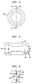
- FIG. 5 is a cross-sectional side view of the part 30 as viewed in the direction of arrows 5 of FIG. 4 at the reference line 32.
- the specific illustrative part 30 shown in FIG. 5 includes a cylindrically shaped left-hand portion that comprises a chamber 34 having a diameter d2.
- the diameter d2 is selected with respect to d1 (FIG. 3) such that the left-hand end of the part 30 of FIG. 5 can be press-fitted onto the neck portion 22 of FIG. 3.
- the design of the two mating structures is such that, when the part 30 is press-fitted onto the neck portion 22, an intimate and robust mechanical connection therebetween is established.
- a good electrical connection between the mating press-fitted conductive structures is also thereby established (for example, less than about one ohm).
- d1 and d2 shown in FIGS. 3 and 5 have the values 8.68 millimeters (mm) and 8.74 mm, respectively.
- the herein-described sleeve member includes a second part 36, an end view of which is shown in FIG. 6.
- the part 36 is designed to fit in a right-hand portion of the part 30 (FIG. 5).
- the part 36 is dimensioned to be pressed into a chamber 38 of the part 30.
- the part 36 is advantageously made of a resilient material comprising, for example, a polymer such as nylon, polyethylene or styrene.
- the specific sleeve member described herein is adapted to accomodate only four leads extending between the aforenoted units 10 and 12.
- the part 36 of FIG. 6 includes four through-openings 38 through 41. All four of these openings may, for example, have the shapes of truncated cones. Such shapes are designed to facilitate entry of leads into the back side of the part 36 (FIG. 6). Leads inserted into the back side extend out from the front of the part 36 shown in FIG. 6.
- the diameter d3 of each circular opening on the front surface of the part 36 of FIG. 6 is only slightly greater than the diameter of the wire intended to extend therethrough.In that way, lateral movement of the leads with respect to their respective front-surface openings is significantly restricted.
- the through-opening 41 is illustratively shown as a keyway in the part 36.
- the keyway 41 allows a greater degree of movement in routing such a ground lead to the bottom of the printed-circuit board.
- the ground lead is typically simply connected to the exterior of the conductive housing, and not hermetically sealed, such greater freedom of movement stands no chance of breaking any of the aforedescribed hermetic seals.
- the keyway 41 illustrated in FIG. 6 serves to facilitate alignment.
- an operator can use the keyway to align the part 36 with respect to the ground wire of the assembly.
- FIG. 7 is a cross-sectional side view of the part 36 shown in FIG. 6 as viewed in the direction of arrows 7 at the reference line 42.
- the funnel-shaped contour of the through-openings 39 and 40 is evident in FIG. 7. (If desired, the keyway 41 may also be funnel-shaped.)
- the diameter d4 of the part 36 of FIG. 7 is slightly greater than the diameter d5 of the entrance 44 to the right-hand chamber 38 shown in FIG. 5.
- the part 36 temporarily deforms sufficiently to snap into the chamber 38, where it is securely maintained, as indicated in FIG. 8.
- the thickness t1 (FIG. 7) of the part 36 was 4.52 mm and the aforenoted diameters d4 and d5 were approximately 8.2 mm and 7.88 mm, respectively.
- FIG. 8 shows an assembled sleeve member 50 made in accordance with the principles of the present invention.
- the assembled member comprises the above-described parts 30 and 36.
- FIG. 8 shows the sleeve member 50 press-fitted onto the neck portion 22 of the conductive housing 24.
- leads 14 extend between the housing 24 and the associated processor unit 12.
- a substantial portion of the longitudinal extent of the leads 14 is encompassed within and thereby shielded by the conductive part 30 of the sleeve member 50.
- intimate electrical contact between the conductive member 50 and the conductive housing 24, when they are press-fitted together, ensures that the member 50 and the housing 24 are electrically connected to the same point of reference potential.
- the funnel-shaped openings 39 and 40 facilitate entry of the right-hand lead ends into their respective openings. It is apparent that when the member 50 is in place, as indicated in FIG. 8, the longitudinally extending leads 14 are significantly limited in the extent to which they can be laterally moved. As a result, when the lead portions to the right of the right-hand end of the member 50 are moved in any direction during assembly or subsequent thereto, there is virtually no liklihood of thereby imposing lateral strain on the hermetic-seal material surrounding the leads in the neck portion 22. Accordingly, in practice the seals remain intact even as the leads 14 are laterally moved to extreme positions.
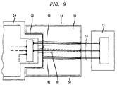
- FIG. 9 shows another specific illustrative embodiment of the principles of the present invention.
- a sleeve member is press-fitted onto the neck portion 22 of the conductive housing 24.
- the sleeve member 54 comprises, for example, a cylindrical non-conductive piece 56 (made, for instance, of a plastic material such as nylon) having a conductive layer 58 (made, for example, of conductive epoxy paint or any other standard conductive coating/layer) on surfaces thereof.
- the left-hand end of the member 54 contains an indented portion designed to snugly engage the neck portion 22 when the member 54 is press-fitted thereon. When so fitted, the conductive layer 58 and the conductive housing 24 are established and maintained in good electrical contact with each other.
- the non-conductive piece 56 of FIG. 9 advantageously contains funnel-shaped longitudinally extending through-openings 60 through 62 through which respective ones of the wires 14 extend.
- no keyway is included.
- a keyway may be included if desired.
- the diameters of the openings 60 through 62 on the right-hand face of the piece 56 are dimensioned to be only slightly greater than the diameters of the wires extending therethrough. In that way, during flexing of the right-hand or free ends of the leads 14, lateral movement of the leads within the neck portion 22 is made virtually impossible.
- the hermetic seals in the portion 22 remain intact with a high degree of certainty over a wide variety of assembly, maintenance and operating conditions.
- the sleeve member 54 including the conductive layer 58 is also effective to shield the portions of the leads 14 that are contained within the indicated channels in the member 54.
Landscapes
- Engineering & Computer Science (AREA)
- Microelectronics & Electronic Packaging (AREA)
- Shielding Devices Or Components To Electric Or Magnetic Fields (AREA)
- Connector Housings Or Holding Contact Members (AREA)
- Installation Of Indoor Wiring (AREA)
Abstract
Description
Claims (12)
- An electronic component assembly comprisinga conductive housing having hermetically sealed electrical leads extending from a specified portion thereof,and a sleeve member having a conductive surface portion and an interior non-conductive portion having longitudinally extending through-openings, said sleeve member being mounted on the specified portion of said housing with said leads extending through said openings and said conductive surface portion in electrical contact with said conductive housing, whereby the longitudinal extent of the leads within said sleeve member is thereby shielded and lateral movement of the leads where they extend through the housing is significantly limited.
- An electronic component assembly comprisinga conductive housing having a neck portion, said housing including circuitry therein,plural through-openings formed in the neck portion of said housing,plural longitudinally extending electrical leads respectively extending through said openings, each of said leads having one end thereof connected to said circuitry,material surrounding each of said leads in said openings to insulate the leads and hermetically seal them with respect to said housing,and a sleeve member fitted to engage said neck portion, said sleeve member includingwhereby, when said sleeve member is engaged with said neck portion, the longitudinal extents of said leads within said sleeve member are electrically shielded and lateral movement of the leads in the material in the openings in said housing is substantially restricted.longitudinally extending through-openings aligned with the leads extending through the openings in said housing, the diameters of the openings where the free ends of the leads extend from said sleeve member being dimensioned to allow substantially no lateral movement of the leads within the sleeve member when said sleeve member is engaged with said neck portion,and outer surface portions comprising conductive material,
- An assembly as in claim 2 wherein at least some of the through-openings in said sleeve member are funnel-shaped to facilitate entry of the free ends of said leads into the openings in said sleeve member when the sleeve member is moved into engagement with said neck portion.
- An assembly as in claim 3 wherein said neck portion and said sleeve member are each cylindrically shaped.
- An assembly as in claim 4 wherein the material surounding the leads in the openings in said housing comprises glass.
- An assembly as in claim 5 wherein at least one of the through-openings in said sleeve member comprises a keyway, thereby to facilitate alignment of said sleeve member with respect to the leads extending from said housing.
- An assembly as in claim 6 wherein said housing comprises stainless steel.
- An assembly as in claim 7 wherein said sleeve member includes first and second parts,said first part comprising a conductive hollow cylinder having an enlarged chamber at each end thereof, one of said chambers being dimensioned to engage the neck portion of said housing, and the other chamber being dimensioned to retain said second part,and said second part comprising a non-conductive cylinder having longitudinally extending through-openings for said leads.
- An assembly as in claim 8 wherein said first part comprises stainless steel.
- An assembly as in claim 9 wherein said second part comprises a resilient material.
- An assembly as in claim 7 wherein said sleeve member comprises a non-conductive cylinder having a conductive layer on outer surfaces thereof, said cylinder having a chamber at one end thereof dimensioned to engage the neck portion of said housing, said cylinder having longitudinally extending through-openings for said leads.
- An assembly as in claim 11 wherein said non-conductive cylinder comprises a plastic material.
Applications Claiming Priority (2)
| Application Number | Priority Date | Filing Date | Title |
|---|---|---|---|
| US416069 | 1999-10-12 | ||
| US09/416,069 US6245993B1 (en) | 1999-10-12 | 1999-10-12 | Electronic assembly having shielding and strain-relief member |
Publications (2)
| Publication Number | Publication Date |
|---|---|
| EP1093330A2 true EP1093330A2 (en) | 2001-04-18 |
| EP1093330A3 EP1093330A3 (en) | 2001-11-21 |
Family
ID=23648409
Family Applications (1)
| Application Number | Title | Priority Date | Filing Date |
|---|---|---|---|
| EP00308868A Withdrawn EP1093330A3 (en) | 1999-10-12 | 2000-10-09 | Electronic assembly having shielding and strain-relief member |
Country Status (5)
| Country | Link |
|---|---|
| US (1) | US6245993B1 (en) |
| EP (1) | EP1093330A3 (en) |
| JP (1) | JP2001167842A (en) |
| AU (1) | AU6411900A (en) |
| CA (1) | CA2322609A1 (en) |
Families Citing this family (3)
| Publication number | Priority date | Publication date | Assignee | Title |
|---|---|---|---|---|
| US7478108B2 (en) * | 1999-12-06 | 2009-01-13 | Micro Strain, Inc. | Data collection using sensing units and separate control units with all power derived from the control units |
| US6841731B1 (en) * | 2003-12-18 | 2005-01-11 | Emerson Electric Co. | Terminal assembly |
| DE102010063683A1 (en) * | 2010-12-21 | 2012-06-21 | Robert Bosch Gmbh | Actuator device and method of manufacturing an actuator device |
Family Cites Families (9)
| Publication number | Priority date | Publication date | Assignee | Title |
|---|---|---|---|---|
| US3302072A (en) * | 1967-01-31 | Electrical device with casing seal mem- bers comprising a cavity in meeting surface | ||
| US252392A (en) * | 1882-01-17 | Hie am s | ||
| US2513870A (en) * | 1948-01-23 | 1950-07-04 | Reeves Hoffman Corp | Hermetically sealed crystal |
| US2688737A (en) * | 1950-01-13 | 1954-09-07 | American Phenolic Corp | Hermetically sealed connector |
| US3684927A (en) * | 1971-07-12 | 1972-08-15 | Gen Electric | Electrolytic capacitor with improved seal |
| GB1600029A (en) * | 1977-11-24 | 1981-10-14 | Plessey Co Ltd | Electrolytic capacitors |
| NL7806822A (en) * | 1978-06-24 | 1979-12-28 | Philips Nv | ELECTRICAL DISCHARGE TUBE FITTED WITH A GLASS-SEALED ELECTRICAL FEED AND METHOD FOR THE MANUFACTURE OF SUCH ELECTRICAL CONNECTION. |
| US4650276A (en) * | 1983-12-21 | 1987-03-17 | Gte Laboratories Incorporated | Optical fiber connected broadband microwave package for optoelectronic components |
| US5696474A (en) * | 1995-12-22 | 1997-12-09 | Watkins-Johnson Company | High frequency hermetically sealed electrical feed through connector |
-
1999
- 1999-10-12 US US09/416,069 patent/US6245993B1/en not_active Expired - Lifetime
-
2000
- 2000-10-06 CA CA002322609A patent/CA2322609A1/en not_active Abandoned
- 2000-10-09 EP EP00308868A patent/EP1093330A3/en not_active Withdrawn
- 2000-10-10 AU AU64119/00A patent/AU6411900A/en not_active Abandoned
- 2000-10-12 JP JP2000311432A patent/JP2001167842A/en active Pending
Also Published As
| Publication number | Publication date |
|---|---|
| CA2322609A1 (en) | 2001-04-12 |
| US6245993B1 (en) | 2001-06-12 |
| AU6411900A (en) | 2001-04-26 |
| EP1093330A3 (en) | 2001-11-21 |
| JP2001167842A (en) | 2001-06-22 |
Similar Documents
| Publication | Publication Date | Title |
|---|---|---|
| EP0247874B1 (en) | Electrical and fibre optic connector | |
| US6435911B1 (en) | Data signal connector with protective overmold | |
| EP0769828B1 (en) | Fully insulated, fully shielded electrical connector arrangement | |
| US5890922A (en) | Electrical connector | |
| US5242318A (en) | Multipole connector for electronic signal lines | |
| US10403995B2 (en) | Electrical connector, electronic component, and assembly method | |
| US9158082B2 (en) | Photoelectric connector | |
| AU2003225633A1 (en) | Emi feedthrough filter terminal assembly utilizing hermetic seal for electrical attachment between lead wires and capacitor | |
| CN106654732B (en) | Network connector assembly and network connector system | |
| US20200400708A1 (en) | Piezoelectric sensor | |
| US4818056A (en) | Optical connector with direct mounted photo diode | |
| US12451628B2 (en) | Electrical connector and electrical connector set including said electrical connector | |
| JPH09237656A (en) | Ground-reinforced electrical connector | |
| US20040002261A1 (en) | Connector assembly with a floating shield dividing contacts formed in differential pairs | |
| US6245993B1 (en) | Electronic assembly having shielding and strain-relief member | |
| CN119209124A (en) | Hermetically sealed controlled impedance feedthrough assembly | |
| KR20160101520A (en) | Receptacle connector | |
| US8142204B2 (en) | Automation appliance which uses the same configuration plug connectors for connecting antenna plug and coaxial cable | |
| US20200381871A1 (en) | Connector | |
| WO2001017071A1 (en) | Connector block for a terminal assembly | |
| US5070314A (en) | Hermetic module containing microwave component | |
| US20220302366A1 (en) | Piezoelectric transducer | |
| IL136636A (en) | Optically coupled isolator housing and assembly | |
| JPH075676Y2 (en) | Electronic device | |
| CN1154205C (en) | plug |
Legal Events
| Date | Code | Title | Description |
|---|---|---|---|
| PUAI | Public reference made under article 153(3) epc to a published international application that has entered the european phase |
Free format text: ORIGINAL CODE: 0009012 |
|
| AK | Designated contracting states |
Kind code of ref document: A2 Designated state(s): AT BE CH CY DE DK ES FI FR GB GR IE IT LI LU MC NL PT SE |
|
| AX | Request for extension of the european patent |
Free format text: AL;LT;LV;MK;RO;SI |
|
| PUAL | Search report despatched |
Free format text: ORIGINAL CODE: 0009013 |
|
| AK | Designated contracting states |
Kind code of ref document: A3 Designated state(s): AT BE CH CY DE DK ES FI FR GB GR IE IT LI LU MC NL PT SE |
|
| AX | Request for extension of the european patent |
Free format text: AL;LT;LV;MK;RO;SI |
|
| AKX | Designation fees paid | ||
| REG | Reference to a national code |
Ref country code: DE Ref legal event code: 8566 |
|
| STAA | Information on the status of an ep patent application or granted ep patent |
Free format text: STATUS: THE APPLICATION IS DEEMED TO BE WITHDRAWN |
|
| 18D | Application deemed to be withdrawn |
Effective date: 20020522 |