EP1093295A2 - Image processing device and image processing method - Google Patents
Image processing device and image processing method Download PDFInfo
- Publication number
- EP1093295A2 EP1093295A2 EP00121400A EP00121400A EP1093295A2 EP 1093295 A2 EP1093295 A2 EP 1093295A2 EP 00121400 A EP00121400 A EP 00121400A EP 00121400 A EP00121400 A EP 00121400A EP 1093295 A2 EP1093295 A2 EP 1093295A2
- Authority
- EP
- European Patent Office
- Prior art keywords
- blocks
- block
- density
- image data
- image processing
- Prior art date
- Legal status (The legal status is an assumption and is not a legal conclusion. Google has not performed a legal analysis and makes no representation as to the accuracy of the status listed.)
- Withdrawn
Links
Images






Classifications
-
- G—PHYSICS
- G06—COMPUTING OR CALCULATING; COUNTING
- G06T—IMAGE DATA PROCESSING OR GENERATION, IN GENERAL
- G06T5/00—Image enhancement or restoration
- G06T5/40—Image enhancement or restoration using histogram techniques
-
- G—PHYSICS
- G06—COMPUTING OR CALCULATING; COUNTING
- G06T—IMAGE DATA PROCESSING OR GENERATION, IN GENERAL
- G06T5/00—Image enhancement or restoration
- G06T5/90—Dynamic range modification of images or parts thereof
- G06T5/94—Dynamic range modification of images or parts thereof based on local image properties, e.g. for local contrast enhancement
-
- H—ELECTRICITY
- H04—ELECTRIC COMMUNICATION TECHNIQUE
- H04N—PICTORIAL COMMUNICATION, e.g. TELEVISION
- H04N1/00—Scanning, transmission or reproduction of documents or the like, e.g. facsimile transmission; Details thereof
- H04N1/40—Picture signal circuits
- H04N1/407—Control or modification of tonal gradation or of extreme levels, e.g. background level
- H04N1/4072—Control or modification of tonal gradation or of extreme levels, e.g. background level dependent on the contents of the original
-
- G—PHYSICS
- G06—COMPUTING OR CALCULATING; COUNTING
- G06T—IMAGE DATA PROCESSING OR GENERATION, IN GENERAL
- G06T2207/00—Indexing scheme for image analysis or image enhancement
- G06T2207/20—Special algorithmic details
- G06T2207/20004—Adaptive image processing
- G06T2207/20012—Locally adaptive
-
- G—PHYSICS
- G06—COMPUTING OR CALCULATING; COUNTING
- G06T—IMAGE DATA PROCESSING OR GENERATION, IN GENERAL
- G06T2207/00—Indexing scheme for image analysis or image enhancement
- G06T2207/20—Special algorithmic details
- G06T2207/20021—Dividing image into blocks, subimages or windows
Definitions
- the present invention relates to an image processing device and an image processing method capable of performing image processing to obtain output image data without any occurrence of a chromaticity differentiation loss and jump in brightness and with enhancing a contrast of the image when a printing device such as a printer outputs the image data on a printing paper.
- a printing device such as a printer outputs the image data on a printing paper.
- a color image output means such as a printer which is narrow in color reproduction range
- the chromaticity differentiation loss occurs in a dark part and the jump in brightness occurs in a light part in image data.
- Conventionally, such chromaticity differentiation loss and/or jump in brightness are prevented by enhancing gradation of an image represented by the image data obtained by a color image read-out means such as an image scanner by carrying out contrast enhancement processing on the image data.
- printers and copier machines have been developed previously, these printers of an ink-jet type and a laser type are capable of inputting images data transferred from a personal computer and the like and then printing the image data on a printing paper and so on, and these copier machines are capable of reading optional image by using an optical reader and then printing the image data onto a printing paper.
- the image printing devices such as these printers and copier machines perform a contrast enhancement process based on a histogram uniformity method in order to avoid the missing of detailed edge information about the edge of an original image.
- this method calculates a mapping curve (a density-value conversion curve) per pixel that is obtained by accumulating the histogram of density values, this method causes a drawback to require an enormous time for the operation.
- mapping curve is obtained per region, not per pixel, in order to decrease the processing time to make the histogram, namely in order to perform the making of the histogram at a high speed.
- a size of the reference area as a parameter to be used for determining the degree of enhancement for the detailed information, and a clip value as another parameter to be used for determining the degree of enhancement in the contrast according to the feature of a local region of the image.
- a clip value as another parameter to be used for determining the degree of enhancement in the contrast according to the feature of a local region of the image.
- the wide-view contrast is also decreased because the local contrast is enhanced.
- the local contrast is also decreased because the wide-view contrast is enhanced.
- the degree of the enhancement is also increased, and according to the decreasing of the clip value, the degree of the enhancement is decreased.
- an object of the present invention is, with due consideration to the drawbacks of the conventional technique, to provide an image processing device and an image processing method capable of automatically optimizing the block size of an reference area, of automatically performing an optimum enhancement of the contrast per region, and of easily obtaining output images without any occurrence of a chromaticity differentiation loss and jump in brightness, without any fearing of an unpleasantness, even if a non-skilled operator handles this image processing device and image processing method.
- an image processing device outputs image data to an output device.
- the image processing device comprises a region division means and a contrast enhancement means.
- the region division means inputs image data and for divides the input image data into a plurality of blocks, and further divides each block into a plurality of quasi blocks, and judges whether or not the further division is necessary for each block based on a degree of similarity of density histograms for the quasi blocks and sets quasi blocks as formal blocks based on the judgment. The judgment is repeated for all of the blocks in order to divide the input image data to the plurality of the blocks.
- the contrast enhancement means converts a density of each pixel in image data in each block obtained by the region division means based on a degree of enhancement in contrast according to a density property of each block.
- the contrast enhancement means determines a clip value for each obtained block based on a slope of a tangent in proximity to a mean density of each obtained block on a property curve of an output system as the output device.
- the contrast enhancement means determined a clip value for each obtained block based on a slope of a line that connects two points corresponding to a value of a mean density ⁇ a dispersion of each obtained block on a property curve of an output system as the output device.
- the contrast enhancement means performs a density conversion for pixels in a region corresponding to a boundary section of the blocks by using a density curve obtained by a linear compensation of the density curve of each block after each block of more than the minimum size has been divided so that each divided block is equal in size to the block having the minimum size.
- the contrast enhancement means obtains a difference of mean densities of each pair of blocks that are adjacent to each other in all of the blocks, makes pairs in four blocks in up-down direction and right-left direction, the four blocks being composed of a block including a target pixel and three blocks that are mostly adjacent to the block including the target pixel, judges whether or not the difference of the mean densities of each pair of the blocks is not less than a threshold value that has been set in advance, and decreases a degree of the contrast enhancement according to the number of the pairs of the blocks, whose difference of each pair of the blocks is not less than the threshold value.
- an image processing device outputs image data to an output device.
- the image processing device comprises a region division means and a contrast enhancement means.
- the region division means inputs image data and divides the input image data into a plurality of blocks.
- the contrast enhancement means converts a density of each pixel in image data in each block obtained by the region division means based on a degree of enhancement in contrast according to a density property of each pixel.
- the contrast enhancement means determines a clip value of each block based on a property curve of the output system as a property of the output device and a mean density of each block.
- an image processing method outputs image data to an output device.
- the image processing method comprises the steps of: dividing the input image data into a plurality of blocks; temporarily dividing each block into a plurality of quasi blocks; obtaining a density histogram of each quasi block; judging whether or not a further division is necessary for each block based on a degree of similarity of density histograms for the quasi blocks, and setting quasi blocks as formal blocks based on the judgment; and repeating the judgment for the further division for all of the blocks in order to divide the input image data to the plurality of the blocks.
- an image processing method outputs image data to an output device.
- the image processing method comprises the steps of: dividing input image data into a plurality of blocks; obtaining a mean value of density values of pixels in each obtained block; obtaining a clip value to determine a degree of enhancement in contrast for each block based on the mean value of the density of each obtained block and a property curve of an output system as a property of the output device; obtaining a density histogram of each obtained block; and making a density conversion curve for each obtained block based on the density histogram and the clip value of each obtained block, and converting all of pixels in density based on the density conversion curve.
- the image processing method described above further comprises the steps of obtaining a difference of mean densities of each pair of blocks that are adjacent to each other in all of the obtained blocks, making block pairs in four blocks in up-down direction and right-left direction, the four blocks being composed of a block including a target pixel and three blocks that are mostly adjacent to the block including the target pixel, judging whether or not the difference of the mean densities of each block pair in not less than a threshold value that has been set in advance, and decreasing a clip value to determine a degree of enhancement in contrast according to the number of the pairs of the obtained blocks whose difference of the mean densities is not less than the threshold value.
- the blocks, whose size is greater than that of the block of the minimum size, located in a boundary region of the blocks are divided according to the block of the minimum size, and the density conversion is performed for pixels by using a density curve obtained by a linear compensation of the density curve of each divided block.
- input image are divided into a plurality of blocks automatically. At this time, it is judged whether or not the block is further divided according to a degree of the similarity of the density histograms of the blocks. If it is necessary to further divide the block, this block is divided into a plurality of blocks each having a small size. The division operation is repeated for all of the blocks. As a result, the input image is divided automatically into the blocks each having the optimum size. After the division process, the degree of enhancement in contrast is automatically determined per block in order to perform the density conversion for all of pixels.
- the mean density of the density values of pixels in each block is obtained, and then an optimum clip value to determine the degree of enhancement in contrast is automatically obtained per block according to the mean density per block and the property curve of an output system such as a printer. Then, the density conversion curve per block is made based on the density histogram and the clip value of each block and then the density conversion is performed for all of the pixels. Thereby, it is possible for an unskilled operator to perform the contrast enhancement of the input image data optimally.
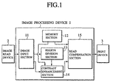
- FIG.1 is a block diagram showing the configuration of the image processing device according to the first embodiment of the present invention.
- a printing device 3 is connected to the image processing device 1. This printing device 3 is located at the following stage of the image processing device 1, and outputs a processed image onto a printing sheet.
- the image processing device 1 comprises an image input section 11 for inputting image data which has been taken by a digital camera, for example, a memory section 12 for storing a property curve of an output system showing a property of the output system and for storing a compensation curve of the output system obtained by converting in reverse the property curve of the output system, a region division section 13 for dividing regions according to the feature of the image data to be processed in a local region, a contrast enhancement section 14 for performing various processes to execute an optimize enhancement for the contrast per region by using the compensation curve of the output system that has been prepared in advance, and a reading compensation section 15 for compensating the density of the image data by using the property curve of the output system.
- a memory section 12 for storing a property curve of an output system showing a property of the output system and for storing a compensation curve of the output system obtained by converting in reverse the property curve of the output system
- a region division section 13 for dividing regions according to the feature of the image data to be processed in a local region
- FIG.2 is a flow chart showing the procedure to obtain the property curve of the output system, which is stored into the memory section 12.
- Step S201 a density dynamic range of the printing device 3 is measured quantitatively.
- FIG.3 is a diagram showing an example of a test pattern to be used for obtaining the property curve of the output system.
- the printing device 3 outputs this test pattern shown in FIG.3, and printed test pattern is then analyzed in order to obtain the property curve of the output system as the property of the printing device 3 at Step S202.
- FIG.4 is a property diagram showing an example of the property curve of the printing device 3 as the output system obtained at Step S202.
- the compensation curve of the output system shown in FIG.5 is obtained based on the input/output property so that the density of the original image is almost equal to the density of the printed image, namely, so that there is no difference of the density information between the original image and the printed image. Both the property curve and the compensation curve of the output system are stored into the memory section 12.
- the image processing device 1 performs the process to enhancement the contrast for the target image to be printed so that the information of small edges in the target image are not eliminated by noise of the printing device 3.
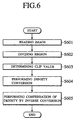
- the image input section 11 in the image processing device 1 inputs and temporarily stores the image data (as the target image to be printed) transferred from outside to an image memory (not shown) at Step S601, and then outputs the image data to both the region division section 13 and the contrast enhancement section 14.
- the region division section 13 divides the image to be printed into a plural blocks (as regions) automatically at Step S602.
- the contrast enhancement section 14 determines a clip value as a parameter in order to determine the degree of the contrast enhancement at Step S603.
- a reference region 003 having a desired size is formed around the target pixel 002 in the image 001 to be converted in density. Then, the density histogram 004 of pixels in the reference region 003 is made.
- pixels whose frequency in the histogram 004 is over a desired clip value 004a are clipped, and these clipped pixels are distributed equally onto other pixels in order to obtain the histogram 005.
- the histogram 006 that is obtained by accumulating the frequencies in the histogram 005 is normalized in order to obtain the density conversion curve. Then, the density conversion for the target pixel is performed.
- the processing requires an enormous calculation time because it is necessary to calculate the density histogram for all of the pixels in the target image data.
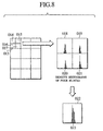
- the region division section 13 in the image processing device 1 of the preferred embodiment divides the image to be processed into plural blocks 013, 014, 015, 016, 017,... , as shown in FIG.8, and then the same density conversion curve is used for the pixels in the same block at Step S602. This causes to decrease the processing time, like the conventional case. Furthermore, because the regions having both a low density value and a high density value may be localized in the image to be processed, the entire image to be processed is divided into the square blocks having different sizes at Step S602, as shown in FIG.8.
- the present invention is not limited by this procedure, for example, it is possible to performs the above processes periodically, and to use a plurality of division stages.
- the proportional distribution of the density conversion curves is used for the peripheral four blocks 009, 010, 011, and 012.
- the output value g(x,y) of the target pixel 008 can be expressed by the following equation (1).
- "g1" to "g4" are density values that are converted by using the density conversion curves obtained based on the block including the target pixel and the four blocks mostly adjacent to the target pixel
- each of "J” and “I” is the length of each side of the square including the target pixel shown in FIG.9
- each of "i” and "j” is the position of the target pixel 008 based on a top point (as a standard point) of this square.
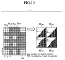
- the large blocks and the intermediate blocks are divided temporarily based on the size of the small block, and the equation (1) is used for the density conversion of the pixels in the boundary regions of the blocks shown by the oblique lines (see FIG.10) in order to avoid occurrence of any block noise.
- the contrast enhancement section 14 uses the same clip value for each block divided by the region division section 13.
- the clip value is the parameter to determine the degree of the contrast enhancing. For example, when the clip value is a large value, the enhancement becomes large, and when the clip value is zero, no enhancement is performed.
- the density value of the pixel in the block is locally plotted between (m- ⁇ ) and(m+ ⁇ ). That is, it may be determined that the dynamic range is wide when the slope of the line 025 (that is equal to the mean density ⁇ the dispersion) made by these two points is greater. That is, it is possible to have the large number of gradations of the output against the small number of gradations of the input.
- the contrast enhancement section 14 determines at Step S603 that the dynamic range in the block is wide and the loss of the information is low. The contrast enhancement section 14 then sets the clip value to a small value. On the contrary, when the slope of the line 025 is small, the contrast enhancement section 14 determines at Step S603 that the loss of the information is large, so that the contrast enhancement section 14 obtains an optimum clip value per block so that the clip value becomes large.
- the contrast enhancement section 14 can obtain the optimum clip value only by using the mean density.
- the contrast enhancement section 14 calculates the slope of the tangent "a" at the point corresponding to the mean density "m" of the input on the property curve "P" of the output system shown in FIG.12, and references the relationship between the slope of the tangent that has been determined in advance and the clip value, and thereby obtain the optimum clip value corresponding to the slope of the tangent "a".
- the method to determine the optimum clip value by using the mean density "m” and the density dispersion " ⁇ 2 " has the feature to eliminate the noise of the property curve of the output system, when compared with the method to determine the clip value only by using the mean density "m". Contrary to this, the method to determine the clip value only by using the mean density "m” has the feature to decrease the amount of the calculation.
- the point indicating the mean density "m” is not limited only by one, it is possible to use values that are in close to the mean density "m" within a negligible amount of error in order to obtain the optimum clip value.
- the contrast enhancement section 14 makes the density conversion curves based on the density histogram of the block including the target pixel in order to perform the density conversion for all of the pixels.
- the contrast enhancement section 14 decreases the clip values because the different of the contrasts are adequately large, and thereby it is not necessary to enhance the contrasts.
- the contrast enhancement section 14 decreases the clip value by a desired value.
- the contrast enhancement section 14 decreases the clip value by 1/4, when the difference of the mean densities of each pair in all pairs in the four blocks in up-down direction and right-left direction is over the threshold value, the contrast enhancement section 14 sets the clip value to zero.
- the contrast enhancement section 14 calculates the difference of the mean densities of each pair of the blocks that are adjacent to each other in all pairs of the blocks, makes the pair of the blocks in the four blocks, namely, blocks including the target pixel and three other blocks mostly adjacent to the target pixel. The contrast enhancement section 14 then judges whether the difference of the mean densities of each pair of the blocks in these four blocks in up-down direction and right-left direction is not less than the threshold value that has been set in advance, and then decreases the clip value by a desired amount according to the number of the pairs having the difference of the mean densities not less than the threshold value in order to suppress the contrast enhancing.
- the contrast enhancement section 14 transfers the target image that has been processed by the contrast enhancement treatment to the read compensation section 15.
- the read compensation section 15 performs the inverse conversion operation of the density for the printing device 3 in order to suppress an absolute difference of the information between the original image and the target image to be printed by using the compensation curve of the output system that is stored in the memory section 12 shown in FIG.5. Then, the read compensation section 15 transfers the obtained image data to be printed to the printing device 3.
- the printing device 3 prints the received printing image data on a printing paper.
- the region division section 13 divides the target image to be printed into a plurality of blocks having a desired size automatically, and the contrast enhancement section 14 determines an optimum clip value for each of these divided blocks automatically in order to perform the enhancing treatment for the contrast per block. Accordingly, it is possible to obtain the image data to be printed having an optimum contrast that has been enhanced easily and rapidly without any skill of an operator.
- the size of the block that requires the density conversion curve is set to an optimum size according to the change of the density of the target image, it is possible to enhance the entire contrast of the image to be printed optimally.
- the clip values are decreased in order to suppress the enhancement of the contrast when all of the mean density values of the adjacent blocks are over a constant value, it is possible to eliminate any occurrence of over-enhancement in contrast.
- the preferred embodiment described above has explained the printing device such as an ink-jet printer, a laser printer, and the like having the function to print the output image transferred from personal computers.
- the present invention is not limited by this preferred embodiment, for example, it is possible to apply the concept of the present invention to optical reading machines such as copier machines capable of reading optional images and this can also obtain the same effect.
- the present invention can be applied to the configuration of the system comprising a scanner, the image processing device 1, and a printer (whose configuration is not limited, for example, it is possible to separate in configuration the printer from the image processing device, and also possible that the printer is incorporated into the image processing device.) in which the image processing device is connected to the scanner and the image reading section 11 reads the image data transferred from the scanner.
- a printer whose configuration is not limited, for example, it is possible to separate in configuration the printer from the image processing device, and also possible that the printer is incorporated into the image processing device.
- the clip value as the parameter it is possible to obtain the clip value as the parameter to automatically determine the degree of the enhancement per block by using the mean density and the property curve of the output system per block.
- the mean density and the dispersion is calculated per block and the clip value is obtained by using the mean density, the dispersion, and the property curve of the output system, it is possible to more eliminate the influence of the noise on the property curve of the output system when compared with the case using only the mean density.
- the present invention it is possible to automatically obtain the optimum clip value per block as a parameter for determining the degree of enhancement in contrast for the block, and because it is also possible to optimally and automatically enhance the contrast of each block based on the parameter, it is possible for an unskilled operator to easily obtain the output image without any occurrence of a chromaticity differentiation loss and jump in brightness and with stability.
Landscapes
- Engineering & Computer Science (AREA)
- Physics & Mathematics (AREA)
- General Physics & Mathematics (AREA)
- Theoretical Computer Science (AREA)
- Multimedia (AREA)
- Signal Processing (AREA)
- Facsimile Image Signal Circuits (AREA)
- Image Processing (AREA)
- Dot-Matrix Printers And Others (AREA)
- Color, Gradation (AREA)
Abstract
Description
Claims (11)
- An image processing device for outputting image data to an output device, comprising:region division means for inputting image data and for dividing the input image data into a plurality of blocks, and for further dividing each block into a plurality of quasi blocks, and for judging whether or not the further division is necessary for each block based on a degree of similarity of density histograms for the quasi blocks and setting quasi blocks as formal blocks based on the judgment, and the judgment is repeated for all of the blocks in order to divide the input image data to the plurality of the blocks; andcontrast enhancement means for converting a density of each pixel in image data in each block obtained by the region division means based on a degree of enhancement in contrast according to a density property of each block.
- An image processing device for outputting image data to an output device, according to claim 1,
wherein the contrast enhancement means determines a clip value for each obtained block based on a slope of a tangent in proximity to a mean density of each obtained block on a property curve of an output system as the output device. - An image processing device for outputting image data to an output device, according to claim 1,
wherein the contrast enhancement means determined a clip value for each obtained block based on a slope of a line that connects two points corresponding to a value of a mean density ±a dispersion of each obtained block on a property curve of an output system as the output device. - An image processing device for outputting image data to an output device, according to claim 1,
wherein the contrast enhancement means performs a density conversion for pixels in a region corresponding to a boundary section of the blocks by using a density curve obtained by a linear compensation of the density curve of each block after each block of more than the minimum size has been divided so that each divided block in equal in size to the block having the minimum size. - An image processing device for outputting image data to an output device, according to claim 2,
wherein the contrast enhancement means obtains a difference of mean densities of each pair of blocks that are adjacent to each other in all of the blocks, makes pairs in four blocks in up-down direction and right-left direction, the four blocks being composed of a block including a target pixel and three blocks that are mostly adjacent to the block including the target pixel, judges whether or not the difference of the mean densities of each pair of the blocks is not less than a threshold value that has been set in advance, and decreases a degree of the contrast enhancement according to the number of the pairs of the blocks, whose difference of each pair of the blocks is not less than the threshold value. - An image processing device for outputting image data to an output device, according to claim 3,
wherein the contrast enhancement means obtains a difference of mean densities of each pair of blocks that are adjacent to each other in all of the blocks, makes pairs in four blocks in up-down direction and right-left direction, the four blocks being composed of a block including a target pixel and three blocks that are mostly adjacent to the block including the target pixel, judges whether or not the difference of the mean densities of each pair of the blocks is not less than a threshold value that has been set in advance, and decreases a degree of the contrast enhancement according to the number of the pairs of the blocks, whose difference of each pair of the blocks is not less than the threshold value. - An image processing device for outputting image data to an output device, comprising:region division means for inputting image data, and for dividing the input image data into a plurality of blocks; andcontrast enhancement means for converting a density of each pixel in image data in each block obtained by the region division means based on a degree of enhancement in contrast according to a density property of each pixel,
wherein the contrast enhancement means determines a clip value of each block based on a property curve of the output system as a property of the output device and a mean density of each block. - An image processing method of outputting image data to an output device, the image data being obtained by enhancement input image data in contrast, comprising the steps of:dividing the input image data into a plurality of blocks;temporarily dividing each block into a plurality of quasi blocks;obtaining a density histogram of each quasi block;judging whether or not a further division is necessary for each block based on a degree of similarity of density histograms for the quasi blocks, and setting quasi blocks as formal blocks based on the judgment; andrepeating the judgment for the further division for all of the blocks in order to divide the input image data to the plurality of the blocks.
- An image processing method of outputting image data to an output device, comprising the steps of:dividing input image data into a plurality of blocks;obtaining a mean value of density values of pixels in each obtained block;obtaining a clip value to determine a degree of enhancement in contrast for each block based on the mean value of the density of each obtained block and a property curve of an output system as a property of the output device;obtaining a density histogram of each obtained block; andmaking a density conversion curve for each obtained block based on the density histogram and the clip value of each obtained block, and converting all of pixels in density based on the density conversion curve.
- An image processing method of outputting image data to an output device, according to claim 9, further comprises the steps of:obtaining a difference of mean densities of each pair of blocks that are adjacent to each other in all of the obtained blocks;making block pairs in four blocks in up-down direction and right-left direction, the four blocks being composed of a block including a target pixel and three blocks that are mostly adjacent to the block including the target pixel;judging whether or not the difference of the mean densities of each block pair is not less than a threshold value that has been set in advance; anddecreasing a clip value to determine a degree of enhancement in contrast according to the number of the pairs of the obtained blocks whose difference of the mean densities is not less than the threshold value.
- An image processing method of outputting image data to an output device, according to claim 9,
wherein the blocks, whose size is greater than that of the block of the minimum size, located in a boundary region of the blocks are divided according to the block of the minimum size, and the density conversion is performed for pixels by using a density curve obtained by a linear compensation of the density curve of each divided block.
Priority Applications (1)
| Application Number | Priority Date | Filing Date | Title |
|---|---|---|---|
| EP08003936A EP1939808A1 (en) | 1999-10-15 | 2000-10-13 | Image processing device and image processing method |
Applications Claiming Priority (2)
| Application Number | Priority Date | Filing Date | Title |
|---|---|---|---|
| JP29447499 | 1999-10-15 | ||
| JP29447499A JP3902894B2 (en) | 1999-10-15 | 1999-10-15 | Image processing apparatus and image processing method |
Related Child Applications (1)
| Application Number | Title | Priority Date | Filing Date |
|---|---|---|---|
| EP08003936A Division EP1939808A1 (en) | 1999-10-15 | 2000-10-13 | Image processing device and image processing method |
Publications (2)
| Publication Number | Publication Date |
|---|---|
| EP1093295A2 true EP1093295A2 (en) | 2001-04-18 |
| EP1093295A3 EP1093295A3 (en) | 2003-11-26 |
Family
ID=17808253
Family Applications (2)
| Application Number | Title | Priority Date | Filing Date |
|---|---|---|---|
| EP08003936A Withdrawn EP1939808A1 (en) | 1999-10-15 | 2000-10-13 | Image processing device and image processing method |
| EP00121400A Withdrawn EP1093295A3 (en) | 1999-10-15 | 2000-10-13 | Image processing device and image processing method |
Family Applications Before (1)
| Application Number | Title | Priority Date | Filing Date |
|---|---|---|---|
| EP08003936A Withdrawn EP1939808A1 (en) | 1999-10-15 | 2000-10-13 | Image processing device and image processing method |
Country Status (3)
| Country | Link |
|---|---|
| US (1) | US6771814B1 (en) |
| EP (2) | EP1939808A1 (en) |
| JP (1) | JP3902894B2 (en) |
Cited By (6)
| Publication number | Priority date | Publication date | Assignee | Title |
|---|---|---|---|---|
| WO2002027657A2 (en) | 2000-09-29 | 2002-04-04 | Hewlett-Packard Company | Image sharpening by variable contrast stretching |
| WO2009082506A1 (en) * | 2007-12-21 | 2009-07-02 | Apple Inc. | Management techniques for video playback |
| EP1788795A4 (en) * | 2004-09-01 | 2010-08-04 | Nec Corp | Image correction system and image correction method |
| ITTO20090161A1 (en) * | 2009-03-03 | 2010-09-04 | Galileo Avionica Spa | EQUALIZATION AND PROCESSING OF IR IMAGES |
| US8035666B2 (en) | 2007-06-26 | 2011-10-11 | Apple Inc. | Dynamic backlight adaptation for black bars with subtitles |
| US8212843B2 (en) | 2007-06-26 | 2012-07-03 | Apple Inc. | Error metric associated with backlight adaptation |
Families Citing this family (22)
| Publication number | Priority date | Publication date | Assignee | Title |
|---|---|---|---|---|
| US7010163B1 (en) * | 2001-04-20 | 2006-03-07 | Shell & Slate Software | Method and apparatus for processing image data |
| JP4120209B2 (en) * | 2001-11-26 | 2008-07-16 | コニカミノルタホールディングス株式会社 | Image recording apparatus, medical image recording apparatus, and medical image system |
| JP4115220B2 (en) * | 2002-09-19 | 2008-07-09 | キヤノン株式会社 | Imaging device |
| GB2417381A (en) | 2004-08-20 | 2006-02-22 | Apical Limited | Dynamic range compression preserving local image contrast |
| JP2006146646A (en) * | 2004-11-22 | 2006-06-08 | Noritsu Koki Co Ltd | Photographic image processing method and apparatus |
| US7986351B2 (en) * | 2005-01-27 | 2011-07-26 | Qualcomm Incorporated | Luma adaptation for digital image processing |
| US7715649B2 (en) * | 2005-02-14 | 2010-05-11 | Fujifilm Corporation | Generation and adjustment of a luminance correction curve to prevent saturation of the image during contrast enhancement |
| US20060274937A1 (en) * | 2005-06-07 | 2006-12-07 | Eric Jeffrey | Apparatus and method for adjusting colors of a digital image |
| KR100756318B1 (en) * | 2006-01-16 | 2007-09-06 | 삼성전자주식회사 | Image processing method and system using gain-controllable cutoff frequency function smoothing |
| JP4003803B1 (en) * | 2006-10-13 | 2007-11-07 | 富士ゼロックス株式会社 | Image processing apparatus, image forming apparatus, and program |
| TWI340586B (en) * | 2006-11-21 | 2011-04-11 | Wintek Corp | Adjusting apparatus for enhancing the contrast of image and method thereof |
| JP4821663B2 (en) * | 2007-03-12 | 2011-11-24 | 日本電気株式会社 | Character noise elimination device, character noise elimination method, character noise elimination program |
| JP5121675B2 (en) * | 2008-11-13 | 2013-01-16 | キヤノン株式会社 | Image processing apparatus, video display apparatus, imaging apparatus, and image processing method |
| US8149245B1 (en) * | 2008-12-16 | 2012-04-03 | The United States Of America As Represented By The Secretary Of The Navy | Adaptive linear contrast method for enhancement of low-visibility imagery |
| JP5481203B2 (en) * | 2010-01-05 | 2014-04-23 | Hoya株式会社 | Endoscope device |
| US8559750B2 (en) * | 2010-11-08 | 2013-10-15 | Lg Innotek Co., Ltd. | Method of performing adaptive contrast enhancement using hyperbolic tangent curve and image histogram |
| US8953688B2 (en) | 2010-11-08 | 2015-02-10 | Sony Corporation | In loop contrast enhancement for improved motion estimation |
| JP6019782B2 (en) * | 2012-06-12 | 2016-11-02 | 大日本印刷株式会社 | Image processing apparatus, image processing method, image processing program, and recording medium |
| JP5202749B1 (en) * | 2012-09-03 | 2013-06-05 | 正浩 小林 | Image processing method |
| RU2509366C1 (en) * | 2012-10-17 | 2014-03-10 | Корпорация "САМСУНГ ЭЛЕКТРОНИКС Ко., Лтд." | System and method of converting hue of flat and three-dimensional images |
| JP6309777B2 (en) | 2014-02-10 | 2018-04-11 | シナプティクス・ジャパン合同会社 | Display device, display panel driver, and display panel driving method |
| EP3483831A1 (en) * | 2017-11-14 | 2019-05-15 | Thomson Licensing | Method and device for modifying a contrast of a visual content |
Family Cites Families (16)
| Publication number | Priority date | Publication date | Assignee | Title |
|---|---|---|---|---|
| JPS5954376A (en) | 1982-09-21 | 1984-03-29 | Konishiroku Photo Ind Co Ltd | Picture processing method |
| FR2633746A1 (en) * | 1988-07-01 | 1990-01-05 | Labo Electronique Physique | DIGITAL IMAGE MODIFICATION METHOD AND SYSTEM FOR IMPLEMENTING THE SAME |
| JPH0363884A (en) * | 1989-08-02 | 1991-03-19 | Hitachi Ltd | Image processing method |
| DE4309878C2 (en) * | 1992-04-06 | 1994-07-21 | Hell Ag Linotype | Method and device for analyzing and correcting the image gradation in image templates |
| US5828784A (en) * | 1992-07-13 | 1998-10-27 | Hitachi Denshi Kabushiki Kaisha | Data coding method and apparatus using a plurality of blocks of different length |
| IL106691A (en) * | 1993-08-13 | 1998-02-08 | Sophis View Tech Ltd | System and method for diagnosis of living tissue diseases |
| US5581370A (en) * | 1995-06-05 | 1996-12-03 | Xerox Corporation | Image-dependent automatic area of interest enhancement |
| JPH09261505A (en) | 1996-01-18 | 1997-10-03 | Konica Corp | Color correction condition calculating method, printing, exposure quantity deciding method, image processing method, image processor, image forming device, printing, exposure device and storage medium |
| KR100189922B1 (en) * | 1996-06-20 | 1999-06-01 | 윤종용 | Circuit and method for improving contrast by using histogram equalization |
| US5774191A (en) * | 1996-06-26 | 1998-06-30 | Intel Corporation | Chroma-key color range determination |
| US6014469A (en) * | 1996-12-31 | 2000-01-11 | Xerox Corporation | System and method for selectively noise-filtering digital images |
| KR100261214B1 (en) * | 1997-02-27 | 2000-07-01 | 윤종용 | Histrogram equalization method and apparatus of a contrast expanding apparatus in image processing system |
| EP0933924B1 (en) | 1998-01-28 | 2004-03-24 | Konica Corporation | Image processing apparatus |
| JP3755986B2 (en) | 1998-04-06 | 2006-03-15 | アイセル株式会社 | Fastening method |
| US6175427B1 (en) * | 1998-04-20 | 2001-01-16 | Xerox Corporation | System and method of tonal correction of independent regions on a compound document |
| US6097849A (en) * | 1998-08-10 | 2000-08-01 | The United States Of America As Represented By The Secretary Of The Navy | Automated image enhancement for laser line scan data |
-
1999
- 1999-10-15 JP JP29447499A patent/JP3902894B2/en not_active Expired - Fee Related
-
2000
- 2000-10-13 EP EP08003936A patent/EP1939808A1/en not_active Withdrawn
- 2000-10-13 EP EP00121400A patent/EP1093295A3/en not_active Withdrawn
- 2000-10-13 US US09/689,704 patent/US6771814B1/en not_active Expired - Lifetime
Cited By (16)
| Publication number | Priority date | Publication date | Assignee | Title |
|---|---|---|---|---|
| WO2002027657A3 (en) * | 2000-09-29 | 2003-03-13 | Hewlett Packard Co | Image sharpening by variable contrast stretching |
| US6915024B1 (en) | 2000-09-29 | 2005-07-05 | Hewlett-Packard Development Company, L.P. | Image sharpening by variable contrast mapping |
| WO2002027657A2 (en) | 2000-09-29 | 2002-04-04 | Hewlett-Packard Company | Image sharpening by variable contrast stretching |
| US7949201B2 (en) | 2004-09-01 | 2011-05-24 | Nec Corporation | Image correction processing system and image correction processing method |
| EP1788795A4 (en) * | 2004-09-01 | 2010-08-04 | Nec Corp | Image correction system and image correction method |
| US8035666B2 (en) | 2007-06-26 | 2011-10-11 | Apple Inc. | Dynamic backlight adaptation for black bars with subtitles |
| US8212843B2 (en) | 2007-06-26 | 2012-07-03 | Apple Inc. | Error metric associated with backlight adaptation |
| US8576256B2 (en) | 2007-06-26 | 2013-11-05 | Apple Inc. | Dynamic backlight adaptation for video images with black bars |
| US8581826B2 (en) | 2007-06-26 | 2013-11-12 | Apple Inc. | Dynamic backlight adaptation with reduced flicker |
| US8629830B2 (en) | 2007-06-26 | 2014-01-14 | Apple Inc. | Synchronizing dynamic backlight adaptation |
| US8648781B2 (en) | 2007-06-26 | 2014-02-11 | Apple Inc. | Technique for adjusting a backlight during a brightness discontinuity |
| US8692755B2 (en) | 2007-06-26 | 2014-04-08 | Apple Inc. | Gamma-correction technique for video playback |
| WO2009082506A1 (en) * | 2007-12-21 | 2009-07-02 | Apple Inc. | Management techniques for video playback |
| US8766902B2 (en) | 2007-12-21 | 2014-07-01 | Apple Inc. | Management techniques for video playback |
| EP2226762A1 (en) * | 2009-03-03 | 2010-09-08 | SELEX Galileo S.p.A. | Equalization and processing of IR images |
| ITTO20090161A1 (en) * | 2009-03-03 | 2010-09-04 | Galileo Avionica Spa | EQUALIZATION AND PROCESSING OF IR IMAGES |
Also Published As
| Publication number | Publication date |
|---|---|
| EP1093295A3 (en) | 2003-11-26 |
| US6771814B1 (en) | 2004-08-03 |
| JP2001113754A (en) | 2001-04-24 |
| JP3902894B2 (en) | 2007-04-11 |
| EP1939808A1 (en) | 2008-07-02 |
Similar Documents
| Publication | Publication Date | Title |
|---|---|---|
| US6771814B1 (en) | Image processing device and image processing method | |
| US6664973B1 (en) | Image processing apparatus, method for processing and image and computer-readable recording medium for causing a computer to process images | |
| US6643398B2 (en) | Image correction device, image correction method and computer program product in memory for image correction | |
| US8175155B2 (en) | Image processing apparatus, image processing method, image processing program, and storage medium | |
| EP1505821B1 (en) | Image processing apparatus, an image forming apparatus and an image processing method | |
| US6049635A (en) | Dotted image area detecting apparatus and dotted image area detecting method | |
| EP1874032B1 (en) | Image processing apparatus and image processing method | |
| JP2000050083A (en) | Digital color copying machine and background noise elimination method | |
| EP0767580B1 (en) | Image processing method and image processing apparatus | |
| US10848644B2 (en) | Image processing apparatus, image processing method, and non-transitory computer-readable storage medium | |
| US7916352B2 (en) | Image processing apparatus, image processing method, program, and recording medium | |
| US6728425B1 (en) | Image processing device | |
| US7689065B2 (en) | Image processing method and apparatus for suppressing positional shift image degradation | |
| JP4113232B2 (en) | Image processing apparatus and image processing method | |
| JP5316312B2 (en) | Image processing device | |
| US20040218220A1 (en) | Enhanced error diffusion | |
| JPH0662230A (en) | Image forming device | |
| JP4549227B2 (en) | Image processing apparatus, image forming apparatus, image processing method, computer program, and recording medium | |
| US20080170265A1 (en) | Image processing device, image forming apparatus, image forming system, image processing method and computer readable medium | |
| JP2702133B2 (en) | Image processing method | |
| JPH05153393A (en) | Image processing device | |
| JP2004145634A (en) | Image processing apparatus and image processing method | |
| JP3957523B2 (en) | Color image processing apparatus, color image processing method, program, and recording medium | |
| JP2004056710A (en) | Color image processing apparatus, color image processing method, program, and recording medium | |
| JPH10276331A (en) | Image processing unit and its method |
Legal Events
| Date | Code | Title | Description |
|---|---|---|---|
| PUAI | Public reference made under article 153(3) epc to a published international application that has entered the european phase |
Free format text: ORIGINAL CODE: 0009012 |
|
| 17P | Request for examination filed |
Effective date: 20001013 |
|
| AK | Designated contracting states |
Kind code of ref document: A2 Designated state(s): AT BE CH CY DE DK ES FI FR GB GR IE IT LI LU MC NL PT SE |
|
| AX | Request for extension of the european patent |
Free format text: AL;LT;LV;MK;RO;SI |
|
| PUAL | Search report despatched |
Free format text: ORIGINAL CODE: 0009013 |
|
| AK | Designated contracting states |
Kind code of ref document: A3 Designated state(s): AT BE CH CY DE DK ES FI FR GB GR IE IT LI LU MC NL PT SE |
|
| AX | Request for extension of the european patent |
Extension state: AL LT LV MK RO SI |
|
| AKX | Designation fees paid |
Designated state(s): DE FR GB |
|
| GRAP | Despatch of communication of intention to grant a patent |
Free format text: ORIGINAL CODE: EPIDOSNIGR1 |
|
| GRAP | Despatch of communication of intention to grant a patent |
Free format text: ORIGINAL CODE: EPIDOSNIGR1 |
|
| RIN1 | Information on inventor provided before grant (corrected) |
Inventor name: NAKAJIMA, MASATO,C/O RISO KAGAKU CORPORATION, R&D |
|
| STAA | Information on the status of an ep patent application or granted ep patent |
Free format text: STATUS: THE APPLICATION IS DEEMED TO BE WITHDRAWN |
|
| 18D | Application deemed to be withdrawn |
Effective date: 20090314 |