EP1092914A2 - Lighting apparatus - Google Patents
Lighting apparatus Download PDFInfo
- Publication number
- EP1092914A2 EP1092914A2 EP00308966A EP00308966A EP1092914A2 EP 1092914 A2 EP1092914 A2 EP 1092914A2 EP 00308966 A EP00308966 A EP 00308966A EP 00308966 A EP00308966 A EP 00308966A EP 1092914 A2 EP1092914 A2 EP 1092914A2
- Authority
- EP
- European Patent Office
- Prior art keywords
- modules
- lighting apparatus
- module
- light fitting
- array
- Prior art date
- Legal status (The legal status is an assumption and is not a legal conclusion. Google has not performed a legal analysis and makes no representation as to the accuracy of the status listed.)
- Withdrawn
Links
Images





Classifications
-
- F—MECHANICAL ENGINEERING; LIGHTING; HEATING; WEAPONS; BLASTING
- F21—LIGHTING
- F21S—NON-PORTABLE LIGHTING DEVICES; SYSTEMS THEREOF; VEHICLE LIGHTING DEVICES SPECIALLY ADAPTED FOR VEHICLE EXTERIORS
- F21S2/00—Systems of lighting devices, not provided for in main groups F21S4/00 - F21S10/00 or F21S19/00, e.g. of modular construction
-
- F—MECHANICAL ENGINEERING; LIGHTING; HEATING; WEAPONS; BLASTING
- F21—LIGHTING
- F21V—FUNCTIONAL FEATURES OR DETAILS OF LIGHTING DEVICES OR SYSTEMS THEREOF; STRUCTURAL COMBINATIONS OF LIGHTING DEVICES WITH OTHER ARTICLES, NOT OTHERWISE PROVIDED FOR
- F21V21/00—Supporting, suspending, or attaching arrangements for lighting devices; Hand grips
- F21V21/005—Supporting, suspending, or attaching arrangements for lighting devices; Hand grips for several lighting devices in an end-to-end arrangement, i.e. light tracks
-
- F—MECHANICAL ENGINEERING; LIGHTING; HEATING; WEAPONS; BLASTING
- F21—LIGHTING
- F21V—FUNCTIONAL FEATURES OR DETAILS OF LIGHTING DEVICES OR SYSTEMS THEREOF; STRUCTURAL COMBINATIONS OF LIGHTING DEVICES WITH OTHER ARTICLES, NOT OTHERWISE PROVIDED FOR
- F21V21/00—Supporting, suspending, or attaching arrangements for lighting devices; Hand grips
- F21V21/14—Adjustable mountings
- F21V21/30—Pivoted housings or frames
-
- F—MECHANICAL ENGINEERING; LIGHTING; HEATING; WEAPONS; BLASTING
- F21—LIGHTING
- F21V—FUNCTIONAL FEATURES OR DETAILS OF LIGHTING DEVICES OR SYSTEMS THEREOF; STRUCTURAL COMBINATIONS OF LIGHTING DEVICES WITH OTHER ARTICLES, NOT OTHERWISE PROVIDED FOR
- F21V23/00—Arrangement of electric circuit elements in or on lighting devices
- F21V23/06—Arrangement of electric circuit elements in or on lighting devices the elements being coupling devices, e.g. connectors
-
- F—MECHANICAL ENGINEERING; LIGHTING; HEATING; WEAPONS; BLASTING
- F21—LIGHTING
- F21W—INDEXING SCHEME ASSOCIATED WITH SUBCLASSES F21K, F21L, F21S and F21V, RELATING TO USES OR APPLICATIONS OF LIGHTING DEVICES OR SYSTEMS
- F21W2131/00—Use or application of lighting devices or systems not provided for in codes F21W2102/00-F21W2121/00
- F21W2131/40—Lighting for industrial, commercial, recreational or military use
Definitions
- the invention relates to lighting apparatus.
- modules For homes, offices, shops and other lighting it is known to provide lighting consisting of a number of separate electric light fittings mounted in modules and supported by brackets or tracks.
- the modules may be movable and the fittings may be swivable within the modules.
- At present such modules when provided in a composite structure for multiple use, are normally permanently joined together in a predetermined fixed array.
- multiple modules may require partial disassembly or are at least physically awkward for carrying such operations. This is accentuated in practice as the lighting apparatus itself is often difficult to reach being usually mounted adjacent a ceiling or at an elevated point well above the ground.
- a lighting apparatus comprising a plurality of individual light fitting support modules joined together to provide a composite array for mounting lights in a position of need, in which each module comprises a rectangular frame arranged to be releasably joined and held firmly together at least partially along one of its sides to another of the modules.
- Each module preferably comprises a square frame.
- the one of its sides may be integrally formed with a lip to receive a clip that holds the frame to the array.
- At least the one of the sides may be formed with apertures to receive module joining means.
- Each module includes a light fitting supporting bracket that is preferably releasably mounted to the module.
- the supporting bracket may pivotably hold the light fitting to the module.
- the lighting apparatus may include flexible power cables for supplying each light that are held by clips mounted to the array.
- the frames are preferably made of stainless steel.
- Embodiments of the invention are lighting apparatuses made up of a plurality of various like support modules.
- Each module supports an individual light fitting which is itself includes a reflector support bracket, a bulb, which may be incorporated with the reflector, and electrical connections.
- the modules each comprise a rectangular (preferably square) frame that is joined in use along one side of the frame to along a side of another adjacent frame (or in some cases to or by a spacer, as in Figures 6 and 7 for example). Provision is made to connect to enable all sides of the frames to receive connecting means so that different chosen arrays of using same modules can be made up and releasably joined together according to a user's requirements.
- each support module 10 consists of an open square stainless steel frame having two apertures 11 formed in each side.
- Each aperture 11 is formed with a cavity 12 to receive and surround a shoulder 13 of a sprung rivot 14 (see Figure 5) so that the sides of the frames can be releasably held firmly together against one another along their lengths.
- Each module supports a light fitting 15 (only one is shown in Figure 1), in a manner explained more fully below with reference to Figures 3 and 4.
- Electrical cable clips 16 are mounted to the modules as indicated in the drawing and are shaped to hold respective modules together when in position for use. The cable clips are held in position by the rivots 14 and can be removed from the modules when the rivots 14 have been withdrawn.
- FIG 2 shows two kinds of mounting arrangements for the lighting apparatus.
- Each mounting arrangement includes an anchor bracket 17 that is held to a pair of adjacent modules by bolts 18 that pass through respective of the apertures 11. This means that the anchor brackets 17 can also serve to hold the modules 10 together. It will be noted that no special fixings are required as the apertures 11 are already provided at the correct positions in the modules 10 to receive the anchor brackets 17 and the bolts 18.
- the mounting arrangements either have two arms 19 or two stiff wire connectors 20 (or may have one of each as shown in the Figure) extending between the anchor brackets 17 and wall mounting brackets 21.
- the described mounting arrangements permit a considerable degree of flexibility in the separation and orientation of the lighting apparatus relative to any wall or other like structure to which the brackets 21 are fixed in use.
- FIG 2 also shows a power distribution panel 23 that includes a socket 24, for receiving external power, and four outlets 25 for the light fittings, one of the outlets is shown with a plug 26 in position.
- Flexible cables not shown extend from the plugs 26 to each respective light fitting in use and are held in position by suitable cable push-in clips 16 shown in Figure 1. It will be noted that the panel 23 fits over the sides of one pair of modules 10 and will be held in position by the spring clips 14.
- each light fitting 15 is mounted to its module 10.
- Inwardly protruding stub axle spring clips 27 are held by fixed rivots to opposite sides of the module 10 to receive axles 28 mounted to an outer ring 29.
- An inner ring 30 is pivotably connected to the outer ring to allow swivelling actions indicated by dotted arrows in Figure 3. (Thus, the two rings 29 and 30 provide in effect a "universal coupling" between each of the light fittings 25 and the modules 10.)
- the light fittings can be readily removed. If the power supply cable (not shown) is unclipped and is provided with enough slack, the light fitting can be partially removed. If the power cable is unplugged, the light fitting can be completely removed. In any event, the light fitting 15 can be easily released and removed (using only one hand, say) for maintenance, and more usually and conveniently for replacing a faulty light bulb. When the maintenance has been carried out or a new bulb has been fitted, the light fitting 15 is pressed into and clipped back in position in the module 10.
- the rivots 21 are provided principally for aesthetic reasons.
- the rivots 31 are normally made of suitable plastics material (as indeed the rivots 14 might be) and coloured the same as the colour of the material of the modules 10.
- the rivots 31 therefore visually obscure the cavities 12 of unused apertures 11.
- the rivots 14 may be made of a contrasting colour material to provide a colour pattern effect for the exposed sides of the modules 10.
- FIG. 5 shows five modules 10 in a cross shaped array. Only one light fitting 25 is shown in the Figure.
- the modules 10 are releasably fixed together as before, using the sprung rivots 14.
- Power cable clips and a distribution panel (not shown) will normally be provided, as explained with reference to earlier Figures.
- Figure 6 shows a somewhat different array of modules 10, again only one light fitting 15 is shown.
- An open triangular spacer 32 is placed between two modules.
- the spacer has suitably positioned apertures 33 to receive the sprung rivots 14.
- Figure 7 shows another different form of array using a narrow triangular spacer 34 that is connected to the modules 10 by the sprung rivots 14.
- any number of the modules 10 can be releasably connected together to form chosen arrays as explained, and using if required spacers such as the triangular spacers 32 and 34.
- the same like modules can be manufactured and provided to allow the user to form his own chosen arrays.
- the user may also change the array from time to time if he wishes, because the modules 10 can be readily disconnected. This is also the case if the modules 10 are fixed together in practice by nuts and bolts, or other releasable connecting means.
- the described sprung rivots (or poppets) 14 however have the advantage that they enable the modules to snap together and be pulled apart without the use of hand tools.
- one module in an array may be used to support a transformer instead of a light fitting.
- a transformer is often be required because many lighting bulbs require a low voltage direct current power supply.
- a transformer and distribution panel are mounted in the one module and suitable power supply cables connect to the light fittings from the distribution panel.
- the module used for supporting the transformer normally has an otherwise “standard” frame 10 (or could be in the form of a spacer, such as spacer 32) so that the "transformer" module can be releasably connected anywhere in the array to the other frames 10 in the manner described above.
- the support modules comprise square plate-like frames 35 which can be joined together to each other to form various arrays.
- Each light fitting 36 (which could be the same as light fitting 15) is pivotably supported by a U-shaped bracket 37 that swivably fits to an aperture 38 in the centre of the frame 35.
- the bracket 37 is connected to the frame by a flexible hollow plastic plug 39 that is held in the aperture 38.
- the bracket 37 can be pushed upwards so that an aperture (not shown) in the base of the U slides over the plug 39 and into a peripheral groove formed on the plug.
- a lower end of the plug is squeezed closed and the bracket slipped out of the peripheral groove to allow the bracket to slide downwards and off the plug 39. This action can normally be achieved by using only one hand if necessary.
- Figure 9 shows how two modules 35 are held together by a clip 40 that fits under integrally formed lips 41 of the modules 35.
- the lips 41 extend along each side of the modules 35 so that the modules can be connected together, along any and each of its sides to another module, to make up different shaped arrays when required.
- a power supply distribution panel 42 (generally similar to the panel 23 in Figure 2) is mounted in use to a platform 43 that is held to an upper tongue 44 of the clip 40 by screws 41.
- the lower edge of the platform 43 bears down against top surfaces of the modules 35 to hold the top surfaces in a common plane. When the platform is removed the top surfaces can be tilted to release the clip 40 from the lips 41 and separate the modules from one another.
- the modules 35 can be releasably fitted together as described and made up into various arrays. Suitable triangular or other shaped spacers may be used if required. As before, lighting apparatuses using the modules 35 and the brackets 37 enable the user to make up and change the arrays as desired. The light fittings 36 being easily removed, with the bracket 37, enable servicing and bulb replacement to be carried out without difficulty.
- the frames 10 are preferably square but other rectangular forms may be used. Such non-square forms still enable the sides of modules to be connected against and along at least parts of their lengths to form aesthetically pleasing and robust composite structures. Rectangular (including square) frames may be connected in "stepped" arrays such that a common side of the array is stepped in one direction or the other, for example.
- the frames may be made wholly or partly of suitable plastics material or of metals other than stainless steel.
Landscapes
- Engineering & Computer Science (AREA)
- General Engineering & Computer Science (AREA)
- Non-Portable Lighting Devices Or Systems Thereof (AREA)
- Fastening Of Light Sources Or Lamp Holders (AREA)
Abstract
Description
- The invention relates to lighting apparatus.
- For homes, offices, shops and other lighting it is known to provide lighting consisting of a number of separate electric light fittings mounted in modules and supported by brackets or tracks. The modules may be movable and the fittings may be swivable within the modules. At present such modules, when provided in a composite structure for multiple use, are normally permanently joined together in a predetermined fixed array. For maintenance, and in particular for changing bulbs as usually required from time to time, multiple modules may require partial disassembly or are at least physically awkward for carrying such operations. This is accentuated in practice as the lighting apparatus itself is often difficult to reach being usually mounted adjacent a ceiling or at an elevated point well above the ground.
- It is an object of the invention to overcome or at least reduce one or both of these problems.
- According to the invention there is provided a lighting apparatus comprising a plurality of individual light fitting support modules joined together to provide a composite array for mounting lights in a position of need, in which each module comprises a rectangular frame arranged to be releasably joined and held firmly together at least partially along one of its sides to another of the modules.
- Each module preferably comprises a square frame.
- The one of its sides may be integrally formed with a lip to receive a clip that holds the frame to the array.
- At least the one of the sides may be formed with apertures to receive module joining means.
- Each module includes a light fitting supporting bracket that is preferably releasably mounted to the module. The supporting bracket may pivotably hold the light fitting to the module.
- The lighting apparatus may include flexible power cables for supplying each light that are held by clips mounted to the array.
- The frames are preferably made of stainless steel.
- Lighting apparatuses according to the invention will now be described by way of example with reference to the accompanying drawings in which :
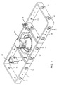
- Figure 1 is a top isometric view of three modules joined together;
- Figure 2 is a top isometric view of four modules joined together;
- Figure 3 is a top isometric view of one module;
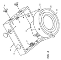
- Figure 4 is a bottom isometric view of one module with a light fitting separated from the module;
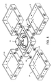
- Figure 5 is a top exploded view of five modules;
- Figure 6 is a top isometric view of three modules;
- Figure 7 is a top isometric view of two modules;
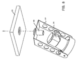
- Figure 8 is a bottom isometric view of a different module; and
- Figure 9 is a top isometric view of two of the different modules.
-
- Embodiments of the invention are lighting apparatuses made up of a plurality of various like support modules. Each module supports an individual light fitting which is itself includes a reflector support bracket, a bulb, which may be incorporated with the reflector, and electrical connections. The modules each comprise a rectangular (preferably square) frame that is joined in use along one side of the frame to along a side of another adjacent frame (or in some cases to or by a spacer, as in Figures 6 and 7 for example). Provision is made to connect to enable all sides of the frames to receive connecting means so that different chosen arrays of using same modules can be made up and releasably joined together according to a user's requirements.
- Referring to the drawings, in Figure 1 each
support module 10 consists of an open square stainless steel frame having twoapertures 11 formed in each side. Eachaperture 11 is formed with acavity 12 to receive and surround ashoulder 13 of a sprung rivot 14 (see Figure 5) so that the sides of the frames can be releasably held firmly together against one another along their lengths. - Each module supports a light fitting 15 (only one is shown in Figure 1), in a manner explained more fully below with reference to Figures 3 and 4.
Electrical cable clips 16 are mounted to the modules as indicated in the drawing and are shaped to hold respective modules together when in position for use. The cable clips are held in position by therivots 14 and can be removed from the modules when therivots 14 have been withdrawn. - In Figure 2, the
same modules 10 are joined together in an array of four modules in a row. Figure 2 shows two kinds of mounting arrangements for the lighting apparatus. Each mounting arrangement includes ananchor bracket 17 that is held to a pair of adjacent modules bybolts 18 that pass through respective of theapertures 11. This means that theanchor brackets 17 can also serve to hold themodules 10 together. It will be noted that no special fixings are required as theapertures 11 are already provided at the correct positions in themodules 10 to receive theanchor brackets 17 and thebolts 18. The mounting arrangements either have twoarms 19 or two stiff wire connectors 20 (or may have one of each as shown in the Figure) extending between theanchor brackets 17 andwall mounting brackets 21. It will be appreciated that the described mounting arrangements permit a considerable degree of flexibility in the separation and orientation of the lighting apparatus relative to any wall or other like structure to which thebrackets 21 are fixed in use. In this respect, it is relatively easy to cut a suitable length for the wire connector 20 (or shorten the wire when required), as the ends of thewire connector 21 are fixed in position bygrub screws 22. - Figure 2 also shows a
power distribution panel 23 that includes asocket 24, for receiving external power, and fouroutlets 25 for the light fittings, one of the outlets is shown with aplug 26 in position. Flexible cables not shown extend from theplugs 26 to each respective light fitting in use and are held in position by suitable cable push-inclips 16 shown in Figure 1. It will be noted that thepanel 23 fits over the sides of one pair ofmodules 10 and will be held in position by thespring clips 14. - In Figures 3 and 4, it can be seen how each light fitting 15 is mounted to its
module 10. Inwardly protruding stubaxle spring clips 27 are held by fixed rivots to opposite sides of themodule 10 to receiveaxles 28 mounted to anouter ring 29. Aninner ring 30 is pivotably connected to the outer ring to allow swivelling actions indicated by dotted arrows in Figure 3. (Thus, the tworings light fittings 25 and themodules 10.) - Importantly, as shown in Figure 4, the light fittings can be readily removed. If the power supply cable (not shown) is unclipped and is provided with enough slack, the light fitting can be partially removed. If the power cable is unplugged, the light fitting can be completely removed. In any event, the
light fitting 15 can be easily released and removed (using only one hand, say) for maintenance, and more usually and conveniently for replacing a faulty light bulb. When the maintenance has been carried out or a new bulb has been fitted, the light fitting 15 is pressed into and clipped back in position in themodule 10. - It will be appreciated that in many commercial applications and/or when there are many lights in use, it is often a matter of routine maintenance to replace all bulbs, whether they are faulty or not, after a certain life span somewhat shorter than their predicated normal lives. The described light fitting removable mountings significantly reduces the time and the effort required to change the bulbs.
- Also shown in Figure 4 are a number of "dummy"
sprung rivots 31. Therivots 21 are provided principally for aesthetic reasons. Therivots 31 are normally made of suitable plastics material (as indeed therivots 14 might be) and coloured the same as the colour of the material of themodules 10. Therivots 31 therefore visually obscure thecavities 12 ofunused apertures 11. When preferred of course, therivots 14 may be made of a contrasting colour material to provide a colour pattern effect for the exposed sides of themodules 10. - Figure 5 shows five
modules 10 in a cross shaped array. Only onelight fitting 25 is shown in the Figure. Themodules 10 are releasably fixed together as before, using thesprung rivots 14. Power cable clips and a distribution panel (not shown) will normally be provided, as explained with reference to earlier Figures. - Figure 6 shows a somewhat different array of
modules 10, again only onelight fitting 15 is shown. An opentriangular spacer 32 is placed between two modules. The spacer has suitably positionedapertures 33 to receive the sprungrivots 14. Likewise, Figure 7 shows another different form of array using a narrowtriangular spacer 34 that is connected to themodules 10 by the sprungrivots 14. - Any number of the
modules 10 can be releasably connected together to form chosen arrays as explained, and using if required spacers such as thetriangular spacers modules 10 can be readily disconnected. This is also the case if themodules 10 are fixed together in practice by nuts and bolts, or other releasable connecting means. The described sprung rivots (or poppets) 14 however have the advantage that they enable the modules to snap together and be pulled apart without the use of hand tools. - It will be noted that one module, say, in an array may be used to support a transformer instead of a light fitting. A transformer is often be required because many lighting bulbs require a low voltage direct current power supply. In that case, a transformer and distribution panel are mounted in the one module and suitable power supply cables connect to the light fittings from the distribution panel. The module used for supporting the transformer normally has an otherwise "standard" frame 10 (or could be in the form of a spacer, such as spacer 32) so that the "transformer" module can be releasably connected anywhere in the array to the
other frames 10 in the manner described above. - In Figures 8 and 9, the support modules comprise square plate-
like frames 35 which can be joined together to each other to form various arrays. Each light fitting 36 (which could be the same as light fitting 15) is pivotably supported by aU-shaped bracket 37 that swivably fits to an aperture 38 in the centre of theframe 35. Thebracket 37 is connected to the frame by a flexible hollowplastic plug 39 that is held in the aperture 38. Thebracket 37 can be pushed upwards so that an aperture (not shown) in the base of the U slides over theplug 39 and into a peripheral groove formed on the plug. To remove thebracket 39, a lower end of the plug is squeezed closed and the bracket slipped out of the peripheral groove to allow the bracket to slide downwards and off theplug 39. This action can normally be achieved by using only one hand if necessary. - Figure 9 shows how two
modules 35 are held together by aclip 40 that fits under integrally formedlips 41 of themodules 35. Thelips 41 extend along each side of themodules 35 so that the modules can be connected together, along any and each of its sides to another module, to make up different shaped arrays when required. - A power supply distribution panel 42 (generally similar to the
panel 23 in Figure 2) is mounted in use to aplatform 43 that is held to anupper tongue 44 of theclip 40 byscrews 41. The lower edge of theplatform 43 bears down against top surfaces of themodules 35 to hold the top surfaces in a common plane. When the platform is removed the top surfaces can be tilted to release theclip 40 from thelips 41 and separate the modules from one another. - The
modules 35 can be releasably fitted together as described and made up into various arrays. Suitable triangular or other shaped spacers may be used if required. As before, lighting apparatuses using themodules 35 and thebrackets 37 enable the user to make up and change the arrays as desired. Thelight fittings 36 being easily removed, with thebracket 37, enable servicing and bulb replacement to be carried out without difficulty. - It will be understood that the
frames 10 are preferably square but other rectangular forms may be used. Such non-square forms still enable the sides of modules to be connected against and along at least parts of their lengths to form aesthetically pleasing and robust composite structures. Rectangular (including square) frames may be connected in "stepped" arrays such that a common side of the array is stepped in one direction or the other, for example. The frames may be made wholly or partly of suitable plastics material or of metals other than stainless steel.
Claims (8)
- A lighting apparatus comprising a plurality of individual light fitting support modules joined together to provide a composite array for mounting lights in a position of need, in which each module comprises a rectangular frame arranged to be releasably joined and held firmly together at least partially along one of its sides to another of the modules.
- A lighting apparatus according to claim 1, in which each module comprises a square frame.
- A lighting apparatus according to claim 1 or 2, in which one of its sides is integrally formed with a lip to receive a clip that holds the frame to the array.
- A lighting apparatus according to claim 1 or 2, in which at least the one of the sides is formed with apertures to receive module joining means.
- A lighting apparatus according to any of claims 1 to 4, in which each module includes a light fitting supporting bracket that is releasably mounted to the module.
- A lighting apparatus according to claim 5, in which the supporting bracket pivotably holds the light fitting to the module.
- A lighting apparatus according to any of claims 1 to 6, including flexible power cables for supplying each light that are held by clips mounted to the array.
- A lighting apparatus according to any of claims 1 to 7, in which the frames are made of stainless steel.
Applications Claiming Priority (2)
| Application Number | Priority Date | Filing Date | Title |
|---|---|---|---|
| GB9924173 | 1999-10-12 | ||
| GB9924173A GB2355298A (en) | 1999-10-12 | 1999-10-12 | Modular framework comprising a plurality of releasably-connected light fitting supports |
Publications (2)
| Publication Number | Publication Date |
|---|---|
| EP1092914A2 true EP1092914A2 (en) | 2001-04-18 |
| EP1092914A3 EP1092914A3 (en) | 2001-08-16 |
Family
ID=10862625
Family Applications (1)
| Application Number | Title | Priority Date | Filing Date |
|---|---|---|---|
| EP00308966A Withdrawn EP1092914A3 (en) | 1999-10-12 | 2000-10-12 | Lighting apparatus |
Country Status (5)
| Country | Link |
|---|---|
| EP (1) | EP1092914A3 (en) |
| CN (1) | CN2447631Y (en) |
| AU (1) | AU6545700A (en) |
| GB (1) | GB2355298A (en) |
| HK (1) | HK1046214A2 (en) |
Cited By (6)
| Publication number | Priority date | Publication date | Assignee | Title |
|---|---|---|---|---|
| EP2056020A1 (en) * | 2007-10-31 | 2009-05-06 | Turn Lights S.R.L. | Articulated support, particularly for lamps |
| ITMI20081531A1 (en) * | 2008-08-21 | 2010-02-22 | Gewiss Spa | BUILT-IN LIGHTING STRUCTURE |
| ITMC20080166A1 (en) * | 2008-09-18 | 2010-03-19 | F A L A Sergio Marchetti S R L | ADJUSTABLE LAMP HOLDER. |
| WO2012034107A3 (en) * | 2010-09-10 | 2012-06-14 | Robe Lighting Inc | A reconfigurable luminaire |
| EP3091528A1 (en) * | 2015-05-05 | 2016-11-09 | Martin Professional ApS | Support frame for video wall |
| WO2025144597A1 (en) * | 2023-12-27 | 2025-07-03 | Apparatus Llc | Modular lighting system |
Families Citing this family (3)
| Publication number | Priority date | Publication date | Assignee | Title |
|---|---|---|---|---|
| ITMI20010385U1 (en) * | 2001-07-11 | 2003-01-11 | Reggiani Illuminazione | MODULAR LIGHTING ELEMENTS FOR RECESSED AND STRIPS OF SUCH ELEMENTS |
| DE20201412U1 (en) | 2002-01-30 | 2002-05-29 | Schlagheck Design GmbH, 81539 München | Luminaire with pivoting spotlights |
| EP2060844B1 (en) * | 2007-11-15 | 2010-04-28 | Ingolf Diez, Medizintechnik | Device for supporting medical instruments |
Family Cites Families (9)
| Publication number | Priority date | Publication date | Assignee | Title |
|---|---|---|---|---|
| US2383007A (en) * | 1943-06-19 | 1945-08-21 | Sylvania Electric Prod | Lighting fixture |
| US4096379A (en) * | 1976-08-24 | 1978-06-20 | Albert Taylor | Modular illumination device |
| FR2417957A1 (en) * | 1978-02-24 | 1979-09-21 | Michel Diefenthal | Modular casing for e.g. spotlight - has front and back parts including interlocking fitments, and finned partition near rear |
| IT8435870U1 (en) * | 1984-06-07 | 1985-12-07 | Ianiro Quartzcolor Spa | MODULAR FLOOR LIGHT FOR THEATERS, PHOTOGRAPHIC, CINEMA, TELEVISION STUDIOS AND SIMILAR |
| US4764851A (en) * | 1987-02-11 | 1988-08-16 | Itc, Incorporated | Light fixture |
| GB2242259A (en) * | 1990-03-22 | 1991-09-25 | Metal Box Plc | A lamp assembly |
| US5551199A (en) * | 1993-11-08 | 1996-09-03 | Hayes; Jerry R. | Box truss for lights |
| IT1282536B1 (en) * | 1995-12-20 | 1998-03-26 | Paolo Targetti | MODULAR SUPPORT STRUCTURE FOR ELECTRICAL OR ELECTRONIC DEVICES, WHICH IN PARTICULAR BUT NOT EXCLUSIVELY APPLIANCES |
| GB2344642A (en) * | 1998-11-27 | 2000-06-14 | Ibl Lighting Limited | Lamp assembly comprising a module which is attachable to a housing |
-
1999
- 1999-10-12 GB GB9924173A patent/GB2355298A/en not_active Withdrawn
-
2000
- 2000-10-10 HK HK01107345A patent/HK1046214A2/en not_active IP Right Cessation
- 2000-10-11 AU AU65457/00A patent/AU6545700A/en not_active Abandoned
- 2000-10-11 CN CN00255068U patent/CN2447631Y/en not_active Expired - Fee Related
- 2000-10-12 EP EP00308966A patent/EP1092914A3/en not_active Withdrawn
Non-Patent Citations (1)
| Title |
|---|
| None |
Cited By (8)
| Publication number | Priority date | Publication date | Assignee | Title |
|---|---|---|---|---|
| EP2056020A1 (en) * | 2007-10-31 | 2009-05-06 | Turn Lights S.R.L. | Articulated support, particularly for lamps |
| ITMI20081531A1 (en) * | 2008-08-21 | 2010-02-22 | Gewiss Spa | BUILT-IN LIGHTING STRUCTURE |
| ITMC20080166A1 (en) * | 2008-09-18 | 2010-03-19 | F A L A Sergio Marchetti S R L | ADJUSTABLE LAMP HOLDER. |
| WO2012034107A3 (en) * | 2010-09-10 | 2012-06-14 | Robe Lighting Inc | A reconfigurable luminaire |
| EP3091528A1 (en) * | 2015-05-05 | 2016-11-09 | Martin Professional ApS | Support frame for video wall |
| CN106128313A (en) * | 2015-05-05 | 2016-11-16 | 马田专业公司 | Support frame for video wall |
| US10379804B2 (en) | 2015-05-05 | 2019-08-13 | Harman Professional Denmark Aps | Support frame for video wall |
| WO2025144597A1 (en) * | 2023-12-27 | 2025-07-03 | Apparatus Llc | Modular lighting system |
Also Published As
| Publication number | Publication date |
|---|---|
| CN2447631Y (en) | 2001-09-12 |
| EP1092914A3 (en) | 2001-08-16 |
| GB2355298A (en) | 2001-04-18 |
| HK1046214A2 (en) | 2002-12-20 |
| GB9924173D0 (en) | 1999-12-15 |
| AU6545700A (en) | 2001-04-26 |
Similar Documents
| Publication | Publication Date | Title |
|---|---|---|
| US10641467B2 (en) | Retrofit system and method for replacing linear fluorescent lamp with LED modules | |
| US4420798A (en) | Adjustable overhead lighting system | |
| US7080927B2 (en) | Modular lighting with blocks | |
| US4654765A (en) | Low voltage lighting system replaceable bulb assembly | |
| CA2611755C (en) | Rotatable magnetic electrical connector | |
| US5722760A (en) | Electro-luminescent light assembly | |
| CN104662364B (en) | Linear illuminator | |
| US9109745B2 (en) | Hanger system for suspendible illuminated fixtures | |
| US20160131341A1 (en) | Lighting Assembly | |
| US20090244915A1 (en) | Interlocking system for hanging decorative lights and fixtures | |
| EP0756688A1 (en) | Housing assembly for illuminated glass tubing | |
| US3999160A (en) | Modular traffic signal apparatus | |
| GB2355298A (en) | Modular framework comprising a plurality of releasably-connected light fitting supports | |
| US5751117A (en) | Modular fluorescent track lighting | |
| DE102018122361A1 (en) | Modular lighting system | |
| US20230121446A1 (en) | Snap-Install Light Assembly and Method of Use | |
| US5331526A (en) | Device for lighting and suspension of a hanging-rod and modular assembly for lighting and suspension of hanging-rods | |
| USRE32899E (en) | Low voltage lighting system replaceable bulb assembly | |
| US10317028B2 (en) | Lighting device made up of lighting elements and striplight made up of a plurality of such lighting devices | |
| US5615942A (en) | Light socket adapter | |
| ES2106996T3 (en) | SPACED MULTIDIMENSIONABLE MODULAR TRIM FRAME FOR SUPPORTS OF ELECTRIC DEVICES. | |
| CN223008695U (en) | Rack for placing articles | |
| CN107084370B (en) | Lamp connecting coupler | |
| US20150338070A1 (en) | Lighted Display Connector | |
| US11767970B2 (en) | Easy mount lighting fixture and electrical receptacle system |
Legal Events
| Date | Code | Title | Description |
|---|---|---|---|
| PUAI | Public reference made under article 153(3) epc to a published international application that has entered the european phase |
Free format text: ORIGINAL CODE: 0009012 |
|
| AK | Designated contracting states |
Kind code of ref document: A2 Designated state(s): AT BE CH CY DE DK ES FI FR GB GR IE IT LI LU MC NL PT SE |
|
| AX | Request for extension of the european patent |
Free format text: AL;LT;LV;MK;RO;SI |
|
| PUAL | Search report despatched |
Free format text: ORIGINAL CODE: 0009013 |
|
| AK | Designated contracting states |
Kind code of ref document: A3 Designated state(s): AT BE CH CY DE DK ES FI FR GB GR IE IT LI LU MC NL PT SE |
|
| AX | Request for extension of the european patent |
Free format text: AL;LT;LV;MK;RO;SI |
|
| RIC1 | Information provided on ipc code assigned before grant |
Free format text: 7F 21S 2/00 A, 7F 21V 21/005 B, 7F 21W 131/40 B, 7F 21W 131:40 Z |
|
| 17P | Request for examination filed |
Effective date: 20011123 |
|
| AKX | Designation fees paid |
Free format text: AT BE CH CY DE DK ES FI FR GB GR IE IT LI LU MC NL PT SE |
|
| 17Q | First examination report despatched |
Effective date: 20040423 |
|
| STAA | Information on the status of an ep patent application or granted ep patent |
Free format text: STATUS: THE APPLICATION IS DEEMED TO BE WITHDRAWN |
|
| 18D | Application deemed to be withdrawn |
Effective date: 20040904 |