EP1092873A2 - Cylinder bore of swash plate compressor with grooves - Google Patents
Cylinder bore of swash plate compressor with grooves Download PDFInfo
- Publication number
- EP1092873A2 EP1092873A2 EP20000119831 EP00119831A EP1092873A2 EP 1092873 A2 EP1092873 A2 EP 1092873A2 EP 20000119831 EP20000119831 EP 20000119831 EP 00119831 A EP00119831 A EP 00119831A EP 1092873 A2 EP1092873 A2 EP 1092873A2
- Authority
- EP
- European Patent Office
- Prior art keywords
- piston
- cylinder bore
- drive shaft
- compressor
- groove
- Prior art date
- Legal status (The legal status is an assumption and is not a legal conclusion. Google has not performed a legal analysis and makes no representation as to the accuracy of the status listed.)
- Withdrawn
Links
- 230000006835 compression Effects 0.000 claims abstract description 42
- 238000007906 compression Methods 0.000 claims abstract description 42
- 239000003507 refrigerant Substances 0.000 claims abstract description 22
- 239000010687 lubricating oil Substances 0.000 claims description 14
- 238000004891 communication Methods 0.000 claims description 2
- 238000006073 displacement reaction Methods 0.000 description 19
- 239000000126 substance Substances 0.000 description 10
- 230000003247 decreasing effect Effects 0.000 description 8
- 230000007246 mechanism Effects 0.000 description 5
- 230000000694 effects Effects 0.000 description 4
- 238000003754 machining Methods 0.000 description 4
- 230000000740 bleeding effect Effects 0.000 description 3
- 230000007423 decrease Effects 0.000 description 3
- 230000003292 diminished effect Effects 0.000 description 3
- 238000000034 method Methods 0.000 description 3
- 230000008569 process Effects 0.000 description 3
- 238000005266 casting Methods 0.000 description 2
- 238000001816 cooling Methods 0.000 description 2
- 230000008878 coupling Effects 0.000 description 2
- 238000010168 coupling process Methods 0.000 description 2
- 238000005859 coupling reaction Methods 0.000 description 2
- 238000005242 forging Methods 0.000 description 2
- 230000004048 modification Effects 0.000 description 2
- 238000012986 modification Methods 0.000 description 2
- 238000003466 welding Methods 0.000 description 2
- 229910000838 Al alloy Inorganic materials 0.000 description 1
- 238000005299 abrasion Methods 0.000 description 1
- 230000002542 deteriorative effect Effects 0.000 description 1
- 238000002474 experimental method Methods 0.000 description 1
- 230000006872 improvement Effects 0.000 description 1
- 239000000314 lubricant Substances 0.000 description 1
- 230000001050 lubricating effect Effects 0.000 description 1
- 239000000463 material Substances 0.000 description 1
- 229910052751 metal Inorganic materials 0.000 description 1
- 239000002184 metal Substances 0.000 description 1
- 239000007769 metal material Substances 0.000 description 1
- 230000004044 response Effects 0.000 description 1
- 239000007787 solid Substances 0.000 description 1
Images





Classifications
-
- F—MECHANICAL ENGINEERING; LIGHTING; HEATING; WEAPONS; BLASTING
- F04—POSITIVE - DISPLACEMENT MACHINES FOR LIQUIDS; PUMPS FOR LIQUIDS OR ELASTIC FLUIDS
- F04B—POSITIVE-DISPLACEMENT MACHINES FOR LIQUIDS; PUMPS
- F04B27/00—Multi-cylinder pumps specially adapted for elastic fluids and characterised by number or arrangement of cylinders
- F04B27/08—Multi-cylinder pumps specially adapted for elastic fluids and characterised by number or arrangement of cylinders having cylinders coaxial with, or parallel or inclined to, main shaft axis
- F04B27/10—Multi-cylinder pumps specially adapted for elastic fluids and characterised by number or arrangement of cylinders having cylinders coaxial with, or parallel or inclined to, main shaft axis having stationary cylinders
- F04B27/1036—Component parts, details, e.g. sealings, lubrication
- F04B27/109—Lubrication
-
- F—MECHANICAL ENGINEERING; LIGHTING; HEATING; WEAPONS; BLASTING
- F04—POSITIVE - DISPLACEMENT MACHINES FOR LIQUIDS; PUMPS FOR LIQUIDS OR ELASTIC FLUIDS
- F04B—POSITIVE-DISPLACEMENT MACHINES FOR LIQUIDS; PUMPS
- F04B27/00—Multi-cylinder pumps specially adapted for elastic fluids and characterised by number or arrangement of cylinders
- F04B27/08—Multi-cylinder pumps specially adapted for elastic fluids and characterised by number or arrangement of cylinders having cylinders coaxial with, or parallel or inclined to, main shaft axis
- F04B27/10—Multi-cylinder pumps specially adapted for elastic fluids and characterised by number or arrangement of cylinders having cylinders coaxial with, or parallel or inclined to, main shaft axis having stationary cylinders
- F04B27/1036—Component parts, details, e.g. sealings, lubrication
- F04B27/1045—Cylinders
-
- F—MECHANICAL ENGINEERING; LIGHTING; HEATING; WEAPONS; BLASTING
- F04—POSITIVE - DISPLACEMENT MACHINES FOR LIQUIDS; PUMPS FOR LIQUIDS OR ELASTIC FLUIDS
- F04B—POSITIVE-DISPLACEMENT MACHINES FOR LIQUIDS; PUMPS
- F04B27/00—Multi-cylinder pumps specially adapted for elastic fluids and characterised by number or arrangement of cylinders
- F04B27/08—Multi-cylinder pumps specially adapted for elastic fluids and characterised by number or arrangement of cylinders having cylinders coaxial with, or parallel or inclined to, main shaft axis
- F04B27/14—Control
- F04B27/16—Control of pumps with stationary cylinders
- F04B27/18—Control of pumps with stationary cylinders by varying the relative positions of a swash plate and a cylinder block
- F04B27/1804—Controlled by crankcase pressure
- F04B2027/1809—Controlled pressure
- F04B2027/1813—Crankcase pressure
-
- F—MECHANICAL ENGINEERING; LIGHTING; HEATING; WEAPONS; BLASTING
- F04—POSITIVE - DISPLACEMENT MACHINES FOR LIQUIDS; PUMPS FOR LIQUIDS OR ELASTIC FLUIDS
- F04B—POSITIVE-DISPLACEMENT MACHINES FOR LIQUIDS; PUMPS
- F04B27/00—Multi-cylinder pumps specially adapted for elastic fluids and characterised by number or arrangement of cylinders
- F04B27/08—Multi-cylinder pumps specially adapted for elastic fluids and characterised by number or arrangement of cylinders having cylinders coaxial with, or parallel or inclined to, main shaft axis
- F04B27/14—Control
- F04B27/16—Control of pumps with stationary cylinders
- F04B27/18—Control of pumps with stationary cylinders by varying the relative positions of a swash plate and a cylinder block
- F04B27/1804—Controlled by crankcase pressure
- F04B2027/1822—Valve-controlled fluid connection
- F04B2027/1827—Valve-controlled fluid connection between crankcase and discharge chamber
-
- F—MECHANICAL ENGINEERING; LIGHTING; HEATING; WEAPONS; BLASTING
- F04—POSITIVE - DISPLACEMENT MACHINES FOR LIQUIDS; PUMPS FOR LIQUIDS OR ELASTIC FLUIDS
- F04B—POSITIVE-DISPLACEMENT MACHINES FOR LIQUIDS; PUMPS
- F04B27/00—Multi-cylinder pumps specially adapted for elastic fluids and characterised by number or arrangement of cylinders
- F04B27/08—Multi-cylinder pumps specially adapted for elastic fluids and characterised by number or arrangement of cylinders having cylinders coaxial with, or parallel or inclined to, main shaft axis
- F04B27/14—Control
- F04B27/16—Control of pumps with stationary cylinders
- F04B27/18—Control of pumps with stationary cylinders by varying the relative positions of a swash plate and a cylinder block
- F04B27/1804—Controlled by crankcase pressure
- F04B2027/184—Valve controlling parameter
- F04B2027/1854—External parameters
-
- F—MECHANICAL ENGINEERING; LIGHTING; HEATING; WEAPONS; BLASTING
- F04—POSITIVE - DISPLACEMENT MACHINES FOR LIQUIDS; PUMPS FOR LIQUIDS OR ELASTIC FLUIDS
- F04B—POSITIVE-DISPLACEMENT MACHINES FOR LIQUIDS; PUMPS
- F04B27/00—Multi-cylinder pumps specially adapted for elastic fluids and characterised by number or arrangement of cylinders
- F04B27/08—Multi-cylinder pumps specially adapted for elastic fluids and characterised by number or arrangement of cylinders having cylinders coaxial with, or parallel or inclined to, main shaft axis
- F04B27/14—Control
- F04B27/16—Control of pumps with stationary cylinders
- F04B27/18—Control of pumps with stationary cylinders by varying the relative positions of a swash plate and a cylinder block
- F04B27/1804—Controlled by crankcase pressure
- F04B2027/1886—Open (not controlling) fluid passage
- F04B2027/1895—Open (not controlling) fluid passage between crankcase and suction chamber
Definitions
- the present invention relates to a piston type compressor which compresses refrigerant gas such as a compressor in an air-conditioner for vehicles.
- a piston 102 reciprocates according to a back-and-forth oscillating movement of a swash plate 101 (right and left in Fig. 10).
- Refrigerant gas is sucked into a compression chamber 104 defined in a cylinder bore 103. Then, the gas is compressed, and the compressed refrigerant gas is discharged from the compression chamber 104.
- a main body 105 of the piston 102 which is inserted into a cylinder bore 103, is hollow.
- an inertia force acting on each part of a compressor due to the reciprocating movement is diminished.
- a stress acting on a coupling portion 106 between the piston 102 and the swash plate 101 is reduced, which results in an increased durability of the piston 102.
- a crank chamber 108 In a housing 107 of the compressor, a crank chamber 108, in which the swash plate 101 is accommodated, has numerous sliding portions such as a coupling portion through shoes 109 between the piston 102 and a swash plate 101. It is necessary to supply a sufficient amount of lubricating oil to the crank chamber 108 to lubricate these sliding portions. Blow-by gas (leakage of the refrigerant gas) from the compression chamber 104 functions as one of the lubricating means. The lubricating oil with the blow-by gas is supplied from the compression chamber 104 to the crank chamber 108.
- a high dimensional accuracy in clearance is needed between an outer circumferential surface 105a of the main body 105 of the piston 102 and an inner circumferential surface 103a of the cylinder bore 103 to adjust the amount of the blow-by gas supplied from the compression chamber 104 into the crank chamber 108.
- a groove 105b is formed in the outer circumferential surface 105a of the main body of the piston 105, and that a blow-by gas passage 110 which connects the compression chamber 104 with the crank chamber 108 is defined between this groove 105b and the inner circumferential surface 103a of the cylinder bore 103.
- the main body 105 of the piston 102 is produced by the following process so that it can be produced easily.
- a cylinder having an equal thickness is formed (a cylinder having an equal thickness contributes to an improvement of an accuracy of finishing, for example since a metal mold can be made simply for a forging or a casting of the main body 105) and then the groove 105b for this cylinder is drilled.
- the thickness of the portion in which the groove 105b is formed becomes thinner than that of the other portions.
- the portion in which this groove 105b is formed has the thickness necessary to keep a certain strength, the other portions which occupy the most portion of the main body 105 has a greater thickness than is necessary.
- the weight of the piston 102 cannot be effectively reduced by hollowing the main body 105, either.
- the invention is achieved by recognizing the problem existing in the conventional art.
- the object is to offer a compressor in which the weight of the piston can be effectively reduced by hollowing a main body, even when a blow-by gas passage is provided.
- the compressor according to the present invention has a following mechanism.
- a crank chamber is formed and a drive shaft is rotatably supported to extend in the crank chamber in the housing.
- a cam plate is integrally rotatably coupled on the drive shaft in the crank chamber.
- a cylinder bore is formed in a cylinder block which constitutes a part of the housing.
- a piston connected to the cam plate is inserted and arranged so that a compression chamber is defined in the cylinder bore.
- This piston comprises a hollow main body inserted into the cylinder bore and a connecting portion connecting the main body to the cam plate.
- the invention has a feature that a groove for a gas, which serves as a communicating means, is formed in the inner circumferential surface of the cylinder bore and a blow-by gas passage is defined between the groove and the outer circumferential surface of the main body of the piston to communicate the compression chamber with the crank chamber.
- the main body of the piston for example, can be a simple cylinder with an equal thickness. Accordingly, the problem that the portion in the main body of the piston corresponding to the blow-by gas passage becomes thinner than the other portions, is avoided. This means that the other portions occupying most of the main body of the piston do not need to be thicker than is necessary.
- the blow-by gas passage is provided as well, the weight of the piston can be effectively reduced by utilizing a hollow main body.
- the present invention has a feature that the groove for a gas is a straight line extending in the direction of the axis of the cylinder bore.
- the groove (the blow-by gas passage) is simply a straight line and it can be formed in the inner circumferential surface of the cylinder bore more easily and more accurately than the following spiral groove, for example.
- the groove has a spiral shape around the axis of the cylinder bore.
- the groove has a spiral shape, so it extends to cross the direction of the reciprocating movement of the piston. Accordingly, it is highly expected that for example, a foreign substance involved between the outer circumferential surface of the main body and the inner circumferential surface of the cylinder bore is taken into the groove by the reciprocating movement of the piston, and that the foreign substance got into this groove with the blow-by gas flowing the blow-by gas passage is discharged into the crank chamber.
- a plurality of the grooves are formed in the inner circumferential surface of the cylinder bore.
- a plurality of blow-by gas passages are provided, even if one of the blow-by gas passages is blocked up by the foreign substance, the blow-by gas to the crank chamber or supply of a lubricating oil can be maintained by the other blow-by gas passages.
- the present invention has a feature that the cam plate is inclinably connected with the drive shaft and the inclination angle of the cam plate is changed by adjusting the pressure in the crank chamber so that the discharge capacity of the compressor can be changed.
- the piston has to slide smoothly in the cylinder bore and follow the cam plate which changes the inclination angle by adjusting the pressure in the crank chamber. Accordingly, when the weight of the piston is effectively reduced and the inertia force acting on the cam plate is diminished, this inertia force diminishes the influence on the control of the inclination angle of the cam plate and the control of the displacement is improved.
- the compressor is of a fixed capacity type, and the inclination angle of the cam plate is fixed.
- the capacity of such a fixed capacity compressor is not influenced in accordance with the rotating speed of the drive shaft. It is always operated at the same inclination angle, that is, the maximum inclination angle of the variable capacity displacement compressor. Accordingly, when the drive shaft rotates at high speed, the speed of the reciprocating movement of the piston is increased excessively in a state continuously maintaining a long stroke of the piston. So, the inertia force acting on various parts of the fixed capacity compressor, due to the reciprocating movement of this piston with heavy weight, at long stroke, at high speed, may be excessive. In a fixed capacity type compressor, which may be in such a severe condition (that is, at high speed and long stroke), if the piston reduces its weight, the inertia force can be diminished effectively.
- the piston has a piston ring around the outer circumferential surface of its main body.
- Such an arrangement with a piston ring is inferior to the arrangement that the outer circumferential surface of the main body directly contacts the inner circumferential surface of the cylinder bore, with respect to the proper leakage of the blow-by gas from the compression chamber to the crank chamber.
- the exclusive blow-by gas passage is particularly effective.
- the piston ring on the piston side does not need machining (such as a notching or a through hole) for the blow-by gas passage and it can save the machining time.
- a first embodiment to a fifth embodiment of a compressor used for a vehicle air conditioner according to the present invention will now be described. Besides, a second embodiment to a fifth embodiment are explained only about the differences from a first embodiment, so the same numbers are used for the same kind of members and the explanation is omitted.
- a front housing 11 is secured to the front side of a cylinder block 12.
- a rear housing 13 is secured through a valve plate assembly 14 to the back of the cylinder block 12.
- the front housing 11, the cylinder block 12 and the rear housing 13 constitute a housing assembly in a compressor.
- a crank chamber 15 is defined by the front housing 11 and the cylinder block 12.
- a drive shaft 16 is rotatably supported by the front housing 11 and the cylinder block 12 so that it is extended through the crank chamber 15.
- the drive shaft 16 is connected with a vehicle engine as an external drive source which is not illustrated, through a clutch mechanism such as a magnetic clutch which is not illustrated. Accordingly, the drive shaft 16 is rotated and driven by the connection of the clutch mechanism when the vehicle engine is operated.
- a rotor 19 is mounted on the drive shaft 16 in the crank chamber 15.
- a swash plate 20, such as a cam plate, is supported slidably and inclinably in the direction of the axis L on the drive shaft 16.
- a hinge mechanism 21 is located between the rotor 19 and the swash plate 20.
- the swash plate 20 is inclinable and rotatable integrally with the drive shaft 16 by the hinge mechanism 21.
- the inclination angle of the swash plate 20 decreases, and when the swash plate 20 moves to the rotor 19 side, the inclination angle of the swash plate 20 increases.
- a plurality of (only one cylinder bore is illustrated in the drawings) cylinder bores 18 are formed in the cylinder block 12, around the axis L of the drive shaft 16, parallel to this axis L.
- One side of a single-headed piston 22 is accommodated in the cylinder bore 18 and the other side of it is engaged with the outer periphery of the swash plate 20 through a shoe 23.
- a compression chamber 17 is defined in the cylinder bore 18 between the front surface of the piston 22 and the valve plate assembly 14. As the swash plate 20 rotates, it wobbles back and forth in the direction of the axis L, and that causes the piston 22 to reciprocate back and forth in the cylinder bore 18. As a result, the volume in the compression chamber 17 changes.
- a suction chamber 24 and a discharge chamber 25 are respectively defined in the rear housing 13.
- a plurality of suction ports 26, suction valves 27, discharge ports 28 and discharge valves 29 are respectively formed on the valve plate assembly 14.
- Refrigerant gas in the suction chamber 24 is sucked into the compression chamber 17 through the suction port 26 and the suction valve 27 while the piston 22 moves from the top dead center to the bottom dead center.
- the refrigerant gas which is drawn into the compression chamber 17 is compressed to a certain pressure as the piston 22 moves from the bottom dead center to the top dead center. Then the compressed gas is discharged to the discharge chamber 25 through the discharge port 28 and the discharge valve 29.
- a bleeding passage 30 communicates between the crank chamber 15 and the suction chamber 24.
- the bleeding passage 30 comprises a passage 30a which is formed along the axis of the drive shaft 16, and a through hole 30b which is formed in the cylinder block 12 and the valve plate assembly 14.
- a supply passage 31 communicates between the discharge chamber 25 and the crank chamber 15.
- a displacement control valve 32 such as a magnetic valve, is placed in the supply passage 31.
- the displacement control valve 32 comprises a solenoid 32a and a valve body 32b which opens and closes the supply passage 31 when the solenoid 32a is excited and de-excited.
- the solenoid 32a of the displacement control valve 32 is excited and de-excited under the control of the computer, which is not illustrated, with reference to a cooling load. Accordingly, the degree of opening of the supply passage 31 is adjusted by the valve body 32b and the pressure in the crank chamber 15 is increased in response to the opening of the supply passage 31. So the difference between the pressure in the crank chamber 15 and the pressure in the compression chamber 17, which acts on the front and rear sides of the piston 22, is adjusted. As a result, the inclination angle of the swash plate 20 is changed and the amount of the stroke of the piston 22 is changed, and thereby adjusts the discharge capacity. When the amount of the stroke of the piston 22 is changed, the position of the bottom dead center of the piston 22 is changed, but the position of the top dead center of it (illustrated in Fig. 1) is unchanged.
- the valve body 32b opens the supply passage 31 and the discharge chamber 25 and the crank chamber 15 are communicated. Accordingly, the high pressure refrigerant gas in the discharge chamber 25 is supplied to the crank chamber 15 through the supply passage 31 and the pressure in the crank chamber 15 rises.
- the pressure in the crank chamber 15 rises the inclination angle of the swash plate 20 decreases. And so the amount of the stroke of the piston 22 is decreased and the discharge capacity is minimized.
- valve body 32b closes the supply passage 31, and the pressure in the crank chamber 15 is lowered due to the pressure release through the bleeding passage 30.
- the pressure in the crank chamber 15 is lowered, the inclination angle of the swash plate 20 increases. So the amount of the stroke of the piston 22 is increased and the discharge capacity is maximized.
- the piston 22 is constituted of a main body 35, which is hollow and accommodated in the cylinder bore 18, and of a connecting portion 36, which connects the main body 35 with the swash plate 20. These two portions are connected in the direction of the axis S of the cylinder bore 18.
- the connecting portion 36 includes a concave portion 36a in the inner circumferential surface (in the side of the axis L of the drive shaft 16) and in this concave portion 36a a pair of shoe seats 36b, which is concave spherical shape, is formed face to face in the direction of the axis S.
- a pair of shoes 23 are accommodated in the concave portion 36a, respectively slidably supported by the corresponding shoe seats 36b.
- the swash plate 20 is held between the front and rear shoes 23 at the outer periphery of the swash plate 20.
- the main body 35 is constituted by a cylindrical portion 37, which has a bottom surface on the side of the compression chamber 17 (on the side of the valve plate assembly 14) in the cylinder bore 18, and by a cover portion 38, which closes the inner space of the cylindrical portion 37 and is formed separately from the cylindrical portion 37.
- the cover portion 38 is integrally formed with the connecting portion 36.
- the cylindrical portion 37 and the cover portion 38 (or the connecting portion 36) are separately made by means such as casting or forging with metallic material of Aluminum alloys. And then they are joined such as welding or frictional welding.
- a wear resistance film C may be applied to the outer circumferential surface 35a of the main body 35.
- the main material of the wear resistance film C is a solid lubricant such as PTFE (polytetrafulloloethylene) and is coated on the outer circumferential surface 35a, for example, from 20 to 40 ⁇ m in thickness.
- the object of the wear resistance film C is to decrease the sliding friction between the outer circumferential surface 35a of the main body 35 and the inner circumferential surface 18a of the cylinder bore 18, and then to prevent both the circumferential surfaces 35a and 18a from deteriorating due to the friction caused by the reciprocating movement of the piston 22.
- a groove 18b is formed in the inner circumferential surface 18a of the cylinder bore 18.
- the blow-by gas passage 39 which communicates the compression chamber 17 with the crank chamber 15 is constituted between the groove 18b and the outer circumferential surface 35a of the main part 35.
- the groove 18b is a straight line and extends parallel to the axis S, from an opening portion to the crank chamber 15 toward the valve plate assembly 14 in the inner circumferential surface 18a of the cylinder bore 18.
- the length of the groove 18b is determined so that the groove 18b is closed against the compression chamber 17 by the outer circumferential surface 35a of the main body 35 when the piston 22 is at the top dead center (illustrated in Figs. 1 and 4). That is, the blow-by gas passage 39 is constituted so that the communication between the compression chamber 17 and the crank chamber 15 is disconnected when the piston 22 is at the top dead center.
- the end portion of the groove 18b on the side of the valve plate assembly 14 is constituted so that the connecting portion 18c between the groove 18b and the inner circumferential surface 18a of the cylinder bore 18 does not have a sharp edge.
- the groove 18b is formed so that the bottom surface of it is gradually sloped to the outer circumferential surface 35a of the main body 35 on the side of the valve plate assembly 14. Accordingly, in particular, when the piston 22 moves from the bottom dead center to the top dead center in the process of the compression and discharge, the connecting portion between the bottom surface of the groove 18b and the inner circumferential surface 18a of the cylinder bore 18 is prevented from hitting the piston 22 (the outer circumferential surface 35a of the main body) and so the damage of the piston 22 is prevented.
- the imaginary straight line D extends intersecting the axis L of the drive shaft 16 and the axis S of the cylinder bore 18.
- the position of the intersecting point P1 located at the farther side with respect to the axis L of the drive shaft 16 is hereby referred to as the twelve o'clock position.
- the position of the intersecting point P2, located at the nearer side with respect to the axis L is hereby referred to as the six o'clock position.
- the groove 18b is formed in the inner circumferential surface 18a of the cylinder bore 18 corresponding to the quarter range which extends between nine o'clock and twelve o'clock, in detail, at the ten o'clock position on the outer circumferetial surface 35a of the main body 35.
- the blow-by of the refrigerant gas from the compression chamber 17 to the crank chamber 15 proceeds mainly through the exclusive blow-by gas passage 39 and lubricating oil suspended in the refrigerant gas in the compression chamber 17 is supplied to the crank chamber 15 with the blow-by gas.
- the lubricating oil is supplied to the crank chamber 15 to lubricate each sliding portion such as the portion between the piston 22 (the shoe seat 36b) and the shoe 23, and the portion between the shoe 23 and the swash plate 20.
- the lubricating oil is supplied initially in the refrigerating circuit in the vehicle air conditioner, and conveyed to the compression chamber with the refrigerant gas.
- the embodiment of the above arrangement has the following effects.
- FIG. 6 A second embodiment is illustrated in Fig. 6.
- the groove 18b (the blow-by gas passage 39) is formed in a spiral around the axis S of the cylinder bore 18 with one or more than one wind (with two wind in this embodiment).
- the length of the groove 18b extending to the valve plate assembly 14 is determined so that the groove 18b is not closed by the outer circumferential surface 35a of the main body 35 even when the piston 22 is at the top dead center. That is, the blow-by gas passage 39 always communicates between the compression chamber 17 and the crank chamber 15, regardless of the position of the stroke of the piston 22.
- This embodiment also has an effect such as "1" and "4" of the first embodiment.
- the groove 18b is formed in a spiral, it extends in the direction crossing with the direction of the reciprocating movement of the piston 22. Accordingly, for example it is highly expected that foreign substances disposed between the outer circumferential surface 35a of the main body and the inner circumferential surface 18a of the cylinder bore 18 are taken into the groove 18b by the reciprocating movement of the piston 22, and the foreign substances are discharged into the crank chamber 15 with the blow-by gas flowing in the blow-by gas passage 39. Thus the foreign substances disposed between the circumferential surfaces 35a and 18a are effectively discharged, and so, for example, peeling off the wear resistance film C caused by the foreign substances can be prevented.
- the lubricating oil conveyed in the blow-by gas passage 39 in a spiral (the circumferential direction of the outer circumferential surface 35a) satisfactorily lubricates whole the circumference between both the circumferential surfaces 35a and 18a.
- a third embodiment is illustrated in Fig. 7.
- a plurality (two) of the spiral grooves 18b are formed.
- Two grooves 18b are formed so that each groove winds in the opposite direction to the other one. Therefore, the grooves cross each other at a plurality of points.
- This embodiment also has not only an effect such as "1" and "4" of the first embodiment, but also has the following effect.
- FIG. 8 A fourth embodiment is illustrated in Fig. 8.
- the swash plate 20 is integrally and rotatably fixed on the drive shaft 16 to rotate integrally and the inclination angle is fixed (in this embodiment, the inclination angle is the same as the maximum inclination angle of the swash plate 20 of the variable displacement compressor because of the relation to the following explanation). That is, the compressor in this embodiment is a fixed displacement compressor.
- the fixed displacement compressor is always operated at the same condition (that the swash plate 20 is inclined at the maximum angle) as the state of the maximum discharge capacity of the variable displacement compressor, regardless of the speed of rotation of the drive shaft 16 since the inclination angle of the swash plate 20 is fixed. Accordingly, when the drive shaft 16 rotates at a high speed, the speed of the reciprocating movement of the piston 22 is increased excessively and there is the possibility that the inertia force acting on various parts of the compressor caused by the reciprocating movement of the piston 22 is excessive. It is particularly worthwhile that the weight of the piston 22 in a compressor which has to meet such severe conditions, is effectively reduced.
- a fifth embodiment is illustrated in Fig. 9.
- the piston 22 in this embodiment has a piston ring 41 around the outer circumferential surface 35a of the main body 35 and is contacted on the inner circumferential surface 18a of the cylinder bore 18 through the piston ring 41.
- the piston ring 41 satisfactorily adheres to the inner circumferential surface 18a of the cylinder bore 18 due to its flexibility. Consequently, it is an ideal arrangement from the point of view of providing a firm seal between the outer circumferential surface 35a of the main body 35 and the inner circumferential surface 18a of the cylinder bore 18.
- the arrangement including the piston ring 41 is inferior to the arrangement of the other embodiment (the arrangement that both the circumferential surfaces 35a and 18a directly contact) as for setting the clearance or the blow-by gas passage to leak the blow-by gas properly from the compression chamber 17 to the crank chamber 15. Accordingly, when the exclusive blow-by gas passage 39 is provided in such an arrangement, it is particularly worthwhile in a point of view that it can accurately set the amount of the blow-by gas, for example.
- the weight of the piston can be effectively reduced by hollowing the main body, even if the blow-by gas passage is provided. Accordingly, the inertia force acting on the various parts of the compressor caused by the reciprocating movement of the piston can be decreased. For example, a stress acting on a connecting portion between the piston and the cam plate is decreased and so the piston can be accomplished durability.
- a compressor is constituted so that the refrigerant gas is compressed in a compression chamber, as the rotating movement of a drive shaft is converted to the reciprocating movement of a piston through a cam plate.
- the object is to offer a compressor in which the weight of the piston can be effectively reduced by hollowing a main body thereof, even when a blow-by gas passage is provided.
- a groove is formed in the inner circumferential surface of a cylinder bore.
- the blow-by gas passage which communicates the compression chamber with a crank chamber, is constituted between the groove and the outer circumferential surface of the main body of the piston.
Landscapes
- Engineering & Computer Science (AREA)
- Mechanical Engineering (AREA)
- General Engineering & Computer Science (AREA)
- Compressors, Vaccum Pumps And Other Relevant Systems (AREA)
- Compressor (AREA)
Abstract
A compressor is constituted so that the refrigerant gas
is compressed in a compression chamber, as the rotating
movement of a drive shaft is converted to the reciprocating
movement of a piston through a cam plate. The object is to
offer a compressor in which the weight of the piston can be
effectively reduced by hollowing a main body thereof, even
when a blow-by gas passage is provided.
A groove is formed in the inner circumferential surface
of a cylinder bore. The blow-by gas passage which
communicates the compression chamber with a crank chamber,
is constituted between the groove and the outer circumferential
surface of the main body of the piston.
Description
- The present invention relates to a piston type compressor which compresses refrigerant gas such as a compressor in an air-conditioner for vehicles.
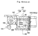
- As shown in Figs. 10 and 11, in this type of compressor a
piston 102 reciprocates according to a back-and-forth oscillating movement of a swash plate 101 (right and left in Fig. 10). Refrigerant gas is sucked into acompression chamber 104 defined in acylinder bore 103. Then, the gas is compressed, and the compressed refrigerant gas is discharged from thecompression chamber 104. - To reduce the weight of the piston, a
main body 105 of thepiston 102, which is inserted into acylinder bore 103, is hollow. When the weight of thepiston 102 is reduced, an inertia force acting on each part of a compressor due to the reciprocating movement is diminished. For example a stress acting on acoupling portion 106 between thepiston 102 and theswash plate 101 is reduced, which results in an increased durability of thepiston 102. - In a
housing 107 of the compressor, acrank chamber 108, in which theswash plate 101 is accommodated, has numerous sliding portions such as a coupling portion throughshoes 109 between thepiston 102 and aswash plate 101. It is necessary to supply a sufficient amount of lubricating oil to thecrank chamber 108 to lubricate these sliding portions. Blow-by gas (leakage of the refrigerant gas) from thecompression chamber 104 functions as one of the lubricating means. The lubricating oil with the blow-by gas is supplied from thecompression chamber 104 to thecrank chamber 108. - A high dimensional accuracy in clearance is needed between an outer
circumferential surface 105a of themain body 105 of thepiston 102 and an innercircumferential surface 103a of thecylinder bore 103 to adjust the amount of the blow-by gas supplied from thecompression chamber 104 into thecrank chamber 108. So it is conventionally suggested that agroove 105b is formed in the outercircumferential surface 105a of the main body of thepiston 105, and that a blow-bygas passage 110 which connects thecompression chamber 104 with thecrank chamber 108 is defined between thisgroove 105b and the innercircumferential surface 103a of thecylinder bore 103. In this way, when the blow-bygas passage 110 is exclusively provided, it is easy to set the accurate clearance defined between the outercircumferential surface 105a of themain body 105 of thepiston 102 and the innercircumferential surface 103a of thecylinder bore 103, and to determine the amount of the blow-by gas accurately. - However, the
main body 105 of thepiston 102 is produced by the following process so that it can be produced easily. For example, a cylinder having an equal thickness is formed (a cylinder having an equal thickness contributes to an improvement of an accuracy of finishing, for example since a metal mold can be made simply for a forging or a casting of the main body 105) and then thegroove 105b for this cylinder is drilled. Accordingly, as it is clear in Fig. 11, it can not be avoided that the thickness of the portion in which thegroove 105b is formed becomes thinner than that of the other portions. And when the portion in which thisgroove 105b is formed has the thickness necessary to keep a certain strength, the other portions which occupy the most portion of themain body 105 has a greater thickness than is necessary. As a result, the weight of thepiston 102 cannot be effectively reduced by hollowing themain body 105, either. - The invention is achieved by recognizing the problem existing in the conventional art. The object is to offer a compressor in which the weight of the piston can be effectively reduced by hollowing a main body, even when a blow-by gas passage is provided.
- The compressor according to the present invention has a following mechanism. A crank chamber is formed and a drive shaft is rotatably supported to extend in the crank chamber in the housing. A cam plate is integrally rotatably coupled on the drive shaft in the crank chamber. A cylinder bore is formed in a cylinder block which constitutes a part of the housing. A piston connected to the cam plate is inserted and arranged so that a compression chamber is defined in the cylinder bore. This piston comprises a hollow main body inserted into the cylinder bore and a connecting portion connecting the main body to the cam plate. When the rotation of the drive shaft is converted to the reciprocating movement of the piston through the cam plate, the refrigerant gas is compressed in the compression chamber. To achieve the above object, the invention has a feature that a groove for a gas, which serves as a communicating means, is formed in the inner circumferential surface of the cylinder bore and a blow-by gas passage is defined between the groove and the outer circumferential surface of the main body of the piston to communicate the compression chamber with the crank chamber. In this arrangement, when the groove is formed in the inner circumferential surface of the cylinder bore to define the blow-by gas passage, the main body of the piston, for example, can be a simple cylinder with an equal thickness. Accordingly, the problem that the portion in the main body of the piston corresponding to the blow-by gas passage becomes thinner than the other portions, is avoided. This means that the other portions occupying most of the main body of the piston do not need to be thicker than is necessary. As a result, when the blow-by gas passage is provided as well, the weight of the piston can be effectively reduced by utilizing a hollow main body.
- Furthermore, the present invention has a feature that the groove for a gas is a straight line extending in the direction of the axis of the cylinder bore. In this arrangement, the groove (the blow-by gas passage) is simply a straight line and it can be formed in the inner circumferential surface of the cylinder bore more easily and more accurately than the following spiral groove, for example.
- Furthermore, in an alternative embodiment of the present invention, the groove has a spiral shape around the axis of the cylinder bore. In this embodiment, the groove has a spiral shape, so it extends to cross the direction of the reciprocating movement of the piston. Accordingly, it is highly expected that for example, a foreign substance involved between the outer circumferential surface of the main body and the inner circumferential surface of the cylinder bore is taken into the groove by the reciprocating movement of the piston, and that the foreign substance got into this groove with the blow-by gas flowing the blow-by gas passage is discharged into the crank chamber.
- Furthermore, in another embodiment of the present invention, a plurality of the grooves are formed in the inner circumferential surface of the cylinder bore. In this embodiment, since a plurality of blow-by gas passages are provided, even if one of the blow-by gas passages is blocked up by the foreign substance, the blow-by gas to the crank chamber or supply of a lubricating oil can be maintained by the other blow-by gas passages.
- Furthermore, the present invention has a feature that the cam plate is inclinably connected with the drive shaft and the inclination angle of the cam plate is changed by adjusting the pressure in the crank chamber so that the discharge capacity of the compressor can be changed. In such a variable displacement compressor, the piston has to slide smoothly in the cylinder bore and follow the cam plate which changes the inclination angle by adjusting the pressure in the crank chamber. Accordingly, when the weight of the piston is effectively reduced and the inertia force acting on the cam plate is diminished, this inertia force diminishes the influence on the control of the inclination angle of the cam plate and the control of the displacement is improved.
- Furthermore, in another embodiment of the present invention, the compressor is of a fixed capacity type, and the inclination angle of the cam plate is fixed. The capacity of such a fixed capacity compressor is not influenced in accordance with the rotating speed of the drive shaft. It is always operated at the same inclination angle, that is, the maximum inclination angle of the variable capacity displacement compressor. Accordingly, when the drive shaft rotates at high speed, the speed of the reciprocating movement of the piston is increased excessively in a state continuously maintaining a long stroke of the piston. So, the inertia force acting on various parts of the fixed capacity compressor, due to the reciprocating movement of this piston with heavy weight, at long stroke, at high speed, may be excessive. In a fixed capacity type compressor, which may be in such a severe condition (that is, at high speed and long stroke), if the piston reduces its weight, the inertia force can be diminished effectively.
- Furthermore, in another embodiment of the present invention, the piston has a piston ring around the outer circumferential surface of its main body. Such an arrangement with a piston ring is inferior to the arrangement that the outer circumferential surface of the main body directly contacts the inner circumferential surface of the cylinder bore, with respect to the proper leakage of the blow-by gas from the compression chamber to the crank chamber. Accordingly, in such an arrangement, the exclusive blow-by gas passage is particularly effective. Besides, when the groove is formed in the inner circumferential surface of the cylinder bore to constitute the blow-by gas passage, the piston ring on the piston side does not need machining (such as a notching or a through hole) for the blow-by gas passage and it can save the machining time.
- The features of the present invention that are believed to be novel are set forth with particularity in the appended claims. The invention together with objects and advantages thereof, may best be understood by reference to the following description of the presently preferred embodiments together with the accompanying drawings in which:
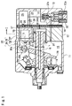
- Fig. 1 is a longitudinal sectional view illustrating a variable displacement compressor according to a first embodiment of the present invention;
- Fig. 2 is an enlarged partial view of Fig. 1, wherein the piston is cutaway;
- Fig. 3 is a view taken along on line I-I of Fig 1;
- Fig. 4 is a view taken along on line II-II of Fig 3;
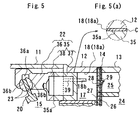
- Fig. 5 is a view under the condition that the piston is at the bottom dead center and Fig. 5(a) is an enlarged view of a wear resistant film;
- Fig. 6 is an enlarged partial cross-sectional view according to a second embodiment of the present invention;
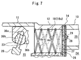
- Fig. 7 is an enlarged partial cross-sectional view according to a third embodiment of the present invention;
- Fig. 8 is a longitudinal sectional view illustrating a fixed capacity compressor according to a fourth embodiment of the present invention;
- Fig. 9 is an enlarged partial cross-sectional view according to a fifth embodiment of the present invention;
- Fig. 10 is an enlarged partial cross-sectional view showing a prior art compressor; and
- Fig. 11 is a view taken along on line III-III of Fig. 10.
-
- A first embodiment to a fifth embodiment of a compressor used for a vehicle air conditioner according to the present invention will now be described. Besides, a second embodiment to a fifth embodiment are explained only about the differences from a first embodiment, so the same numbers are used for the same kind of members and the explanation is omitted.
- As shown in Fig. 1, a
front housing 11 is secured to the front side of acylinder block 12. Arear housing 13 is secured through avalve plate assembly 14 to the back of thecylinder block 12. Thefront housing 11, thecylinder block 12 and therear housing 13 constitute a housing assembly in a compressor. Acrank chamber 15 is defined by thefront housing 11 and thecylinder block 12. - A
drive shaft 16 is rotatably supported by thefront housing 11 and thecylinder block 12 so that it is extended through thecrank chamber 15. Thedrive shaft 16 is connected with a vehicle engine as an external drive source which is not illustrated, through a clutch mechanism such as a magnetic clutch which is not illustrated. Accordingly, thedrive shaft 16 is rotated and driven by the connection of the clutch mechanism when the vehicle engine is operated. - A
rotor 19 is mounted on thedrive shaft 16 in thecrank chamber 15. Aswash plate 20, such as a cam plate, is supported slidably and inclinably in the direction of the axis L on thedrive shaft 16. Ahinge mechanism 21 is located between therotor 19 and theswash plate 20. Theswash plate 20 is inclinable and rotatable integrally with thedrive shaft 16 by thehinge mechanism 21. That is, when the radial center of theswash plate 20 moves to thecylinder block 12 side, the inclination angle of the swash plate 20 (at an angle with the aspect which is perpendicular to the axis L of thedrive shaft 16 and the swash plate 20) decreases, and when theswash plate 20 moves to therotor 19 side, the inclination angle of theswash plate 20 increases. - A plurality of (only one cylinder bore is illustrated in the drawings) cylinder bores 18 are formed in the
cylinder block 12, around the axis L of thedrive shaft 16, parallel to this axis L. One side of a single-headedpiston 22 is accommodated in the cylinder bore 18 and the other side of it is engaged with the outer periphery of theswash plate 20 through ashoe 23. Acompression chamber 17 is defined in the cylinder bore 18 between the front surface of thepiston 22 and thevalve plate assembly 14. As theswash plate 20 rotates, it wobbles back and forth in the direction of the axis L, and that causes thepiston 22 to reciprocate back and forth in the cylinder bore 18. As a result, the volume in thecompression chamber 17 changes. - A
suction chamber 24 and adischarge chamber 25 are respectively defined in therear housing 13. A plurality ofsuction ports 26,suction valves 27,discharge ports 28 anddischarge valves 29 are respectively formed on thevalve plate assembly 14. Refrigerant gas in thesuction chamber 24 is sucked into thecompression chamber 17 through thesuction port 26 and thesuction valve 27 while thepiston 22 moves from the top dead center to the bottom dead center. The refrigerant gas which is drawn into thecompression chamber 17 is compressed to a certain pressure as thepiston 22 moves from the bottom dead center to the top dead center. Then the compressed gas is discharged to thedischarge chamber 25 through thedischarge port 28 and thedischarge valve 29. - A bleeding
passage 30 communicates between thecrank chamber 15 and thesuction chamber 24. The bleedingpassage 30 comprises apassage 30a which is formed along the axis of thedrive shaft 16, and a throughhole 30b which is formed in thecylinder block 12 and thevalve plate assembly 14. Asupply passage 31 communicates between thedischarge chamber 25 and thecrank chamber 15. Adisplacement control valve 32, such as a magnetic valve, is placed in thesupply passage 31. Thedisplacement control valve 32 comprises asolenoid 32a and avalve body 32b which opens and closes thesupply passage 31 when thesolenoid 32a is excited and de-excited. - The
solenoid 32a of thedisplacement control valve 32 is excited and de-excited under the control of the computer, which is not illustrated, with reference to a cooling load. Accordingly, the degree of opening of thesupply passage 31 is adjusted by thevalve body 32b and the pressure in thecrank chamber 15 is increased in response to the opening of thesupply passage 31. So the difference between the pressure in thecrank chamber 15 and the pressure in thecompression chamber 17, which acts on the front and rear sides of thepiston 22, is adjusted. As a result, the inclination angle of theswash plate 20 is changed and the amount of the stroke of thepiston 22 is changed, and thereby adjusts the discharge capacity. When the amount of the stroke of thepiston 22 is changed, the position of the bottom dead center of thepiston 22 is changed, but the position of the top dead center of it (illustrated in Fig. 1) is unchanged. - For example, when the
solenoid 32a is de-excited, thevalve body 32b opens thesupply passage 31 and thedischarge chamber 25 and thecrank chamber 15 are communicated. Accordingly, the high pressure refrigerant gas in thedischarge chamber 25 is supplied to the crankchamber 15 through thesupply passage 31 and the pressure in thecrank chamber 15 rises. When the pressure in thecrank chamber 15 rises, the inclination angle of theswash plate 20 decreases. And so the amount of the stroke of thepiston 22 is decreased and the discharge capacity is minimized. - When the
solenoid 32a is excited, thevalve body 32b closes thesupply passage 31, and the pressure in thecrank chamber 15 is lowered due to the pressure release through the bleedingpassage 30. When the pressure in thecrank chamber 15 is lowered, the inclination angle of theswash plate 20 increases. So the amount of the stroke of thepiston 22 is increased and the discharge capacity is maximized. - Next, the arrangement of the
piston 22 is described in detail. - As shown in Fig. 1 and 5, the
piston 22 is constituted of amain body 35, which is hollow and accommodated in the cylinder bore 18, and of a connectingportion 36, which connects themain body 35 with theswash plate 20. These two portions are connected in the direction of the axis S of the cylinder bore 18. The connectingportion 36 includes aconcave portion 36a in the inner circumferential surface (in the side of the axis L of the drive shaft 16) and in thisconcave portion 36a a pair ofshoe seats 36b, which is concave spherical shape, is formed face to face in the direction of the axis S. A pair ofshoes 23 are accommodated in theconcave portion 36a, respectively slidably supported by the correspondingshoe seats 36b. Theswash plate 20 is held between the front andrear shoes 23 at the outer periphery of theswash plate 20. - The
main body 35 is constituted by acylindrical portion 37, which has a bottom surface on the side of the compression chamber 17 (on the side of the valve plate assembly 14) in the cylinder bore 18, and by acover portion 38, which closes the inner space of thecylindrical portion 37 and is formed separately from thecylindrical portion 37. Thecover portion 38 is integrally formed with the connectingportion 36. Thecylindrical portion 37 and the cover portion 38 (or the connecting portion 36) are separately made by means such as casting or forging with metallic material of Aluminum alloys. And then they are joined such as welding or frictional welding. - As shown in Fig. 5(a), a wear resistance film C may be applied to the outer
circumferential surface 35a of themain body 35. The main material of the wear resistance film C is a solid lubricant such as PTFE (polytetrafulloloethylene) and is coated on the outercircumferential surface 35a, for example, from 20 to 40µm in thickness. The object of the wear resistance film C is to decrease the sliding friction between the outercircumferential surface 35a of themain body 35 and the innercircumferential surface 18a of the cylinder bore 18, and then to prevent both thecircumferential surfaces piston 22. - Next, the feature of the first embodiment is described in detail.
- As shown in Fig. 2 to 5, a
groove 18b is formed in the innercircumferential surface 18a of the cylinder bore 18. The blow-bygas passage 39 which communicates thecompression chamber 17 with thecrank chamber 15 is constituted between thegroove 18b and the outercircumferential surface 35a of themain part 35. Thegroove 18b is a straight line and extends parallel to the axis S, from an opening portion to the crankchamber 15 toward thevalve plate assembly 14 in the innercircumferential surface 18a of the cylinder bore 18. The length of thegroove 18b is determined so that thegroove 18b is closed against thecompression chamber 17 by the outercircumferential surface 35a of themain body 35 when thepiston 22 is at the top dead center (illustrated in Figs. 1 and 4). That is, the blow-bygas passage 39 is constituted so that the communication between thecompression chamber 17 and thecrank chamber 15 is disconnected when thepiston 22 is at the top dead center. - As shown in Fig. 4, the end portion of the
groove 18b on the side of thevalve plate assembly 14 is constituted so that the connectingportion 18c between thegroove 18b and the innercircumferential surface 18a of the cylinder bore 18 does not have a sharp edge. For thegroove 18b is formed so that the bottom surface of it is gradually sloped to the outercircumferential surface 35a of themain body 35 on the side of thevalve plate assembly 14. Accordingly, in particular, when thepiston 22 moves from the bottom dead center to the top dead center in the process of the compression and discharge, the connecting portion between the bottom surface of thegroove 18b and the innercircumferential surface 18a of the cylinder bore 18 is prevented from hitting the piston 22 (the outercircumferential surface 35a of the main body) and so the damage of thepiston 22 is prevented. - As shown in Fig. 3, when viewing the
piston 22 so that the rotating direction R of the drive shaft 16 (the swash plate 20) is clockwise, the imaginary straight line D extends intersecting the axis L of thedrive shaft 16 and the axis S of the cylinder bore 18. Among two intersecting points P1, P2 at which the straight line D and the outercircumferential surface 35a of themain body 35 intersects, the position of the intersecting point P1, located at the farther side with respect to the axis L of thedrive shaft 16, is hereby referred to as the twelve o'clock position. And the position of the intersecting point P2, located at the nearer side with respect to the axis L, is hereby referred to as the six o'clock position. And thegroove 18b is formed in the innercircumferential surface 18a of the cylinder bore 18 corresponding to the quarter range which extends between nine o'clock and twelve o'clock, in detail, at the ten o'clock position on theouter circumferetial surface 35a of themain body 35. In the range which extends between nine o'clock and twelve o'clock on the outercircumferential surface 35a of themain body 35, especially, at the ten o'clock position, though it is not explained in detail, it is proven by experiment and the like that a side force (the reactive force from the innercircumferential surface 18a of the cylinder bore 18 caused by, for example, the inclination of thepiston 22 with respect to the axis S), which is accompanied with the compression reactive force of the refrigerant gas, acts only at lower level than in the other three quarters range (the range between twelve o'clock and three o'clock, the range between three 'clock and six o'clock, and the range between six o'clock and nine o'clock). - Now, the blow-by of the refrigerant gas from the
compression chamber 17 to the crankchamber 15 proceeds mainly through the exclusive blow-bygas passage 39 and lubricating oil suspended in the refrigerant gas in thecompression chamber 17 is supplied to the crankchamber 15 with the blow-by gas. The lubricating oil is supplied to the crankchamber 15 to lubricate each sliding portion such as the portion between the piston 22 (theshoe seat 36b) and theshoe 23, and the portion between theshoe 23 and theswash plate 20. The lubricating oil is supplied initially in the refrigerating circuit in the vehicle air conditioner, and conveyed to the compression chamber with the refrigerant gas. - The embodiment of the above arrangement has the following effects.
- 1. Because the blow-by
gas passage 39 is formed as thegroove 18b in the innercircumferential surface 18a of the cylinder bore 18, themain body 35 can be a simple cylindrical body with an equal thickness. Accordingly, the portion of themain body 35 corresponding to the blow-bygas passage 39 can be avoided being thinner than the other portion. This means that the other portion occupying most of themain body 35 does not need to be thicker than it is needed. As a result, the weight of thepiston 22 can be effectively reduced by utilizing amain body 35, that is hollow, even if the blow-bygas passage 39 is provided. Hence, the inertia force acting on various parts of the compressor due to the reciprocating movement of thepiston 22 can be decreased. For example, the reactive force acting on the connectingportion 36 between thepiston 22 and theswash plate 20 can be decreased, which will result in the increased durability of thepiston 22. - 2. The
groove 18b (the blow-by gas passage 39) is simply formed in a straight line and, for example, it can be formed in the innercircumferential surface 18a of the cylinder bore 18 more easily and precisely than the spiral groove in the following second embodiment. When thegroove 18b is easily formed, the cost for machining it can be reduced, and when it is precisely formed, the accurate setting of the amount of the blow-by gas can be easily performed. - 3. The
groove 18b is formed in the range which extends between nine o'clock and twelve o'clock on the outercircumferential surface 35a of themain body 35. As is above described, the side force accompanied by the compression reactive force of the refrigerant gas acting on the range is small in the outercircumferential surface 35a of the main part. That is, the outercircumferential surface 35a of themain part 35 is not strongly pressed to thegroove 18b in the innercircumferential surface 18a of the cylinder bore 18 and the abrasion and the damage caused between thecircumferential surfaces groove 18b is at the ten o'clock position. - 4. In the variable displacement compressor, the
piston 22 follows theswash plate 20 which changes its inclination angle in accordance with the pressure in thecrank chamber 15, while it needs smooth slide in the cylinder bore 18. Accordingly, as is described in above "1", when the weight of thepiston 22 is reduced and the inertia force acting on theswash plate 20 is decreased, the influence of the inertia force on the control of the inclination angle of theswash plate 20 can be decreased and the displacement control is improved. -
- A second embodiment is illustrated in Fig. 6. In the second embodiment, the
groove 18b (the blow-by gas passage 39) is formed in a spiral around the axis S of the cylinder bore 18 with one or more than one wind (with two wind in this embodiment). And the length of thegroove 18b extending to thevalve plate assembly 14 is determined so that thegroove 18b is not closed by the outercircumferential surface 35a of themain body 35 even when thepiston 22 is at the top dead center. That is, the blow-bygas passage 39 always communicates between thecompression chamber 17 and thecrank chamber 15, regardless of the position of the stroke of thepiston 22. - This embodiment also has an effect such as "1" and "4" of the first embodiment. Moreover, since the
groove 18b is formed in a spiral, it extends in the direction crossing with the direction of the reciprocating movement of thepiston 22. Accordingly, for example it is highly expected that foreign substances disposed between the outercircumferential surface 35a of the main body and the innercircumferential surface 18a of the cylinder bore 18 are taken into thegroove 18b by the reciprocating movement of thepiston 22, and the foreign substances are discharged into thecrank chamber 15 with the blow-by gas flowing in the blow-bygas passage 39. Thus the foreign substances disposed between thecircumferential surfaces - Moreover, the lubricating oil conveyed in the blow-by
gas passage 39 in a spiral (the circumferential direction of the outercircumferential surface 35a) satisfactorily lubricates whole the circumference between both thecircumferential surfaces - A third embodiment is illustrated in Fig. 7. In this embodiment, a plurality (two) of the
spiral grooves 18b (blow-by gas passages) are formed. Twogrooves 18b are formed so that each groove winds in the opposite direction to the other one. Therefore, the grooves cross each other at a plurality of points. - This embodiment also has not only an effect such as "1" and "4" of the first embodiment, but also has the following effect.
- 1. A plurality of the
spiral grooves 18b are more effective to discharge the foreign substances disposed between the outercircumferential surface 35a of the main part and the innercircumferential surface 18a of the cylinder bore 18 and to lubricate whole the circumference between thecircumferential surfaces single spiral groove 18b described in the second embodiment. - 2. When a plurality of the
grooves 18b (blow-by gas passages 39) are provided, even if a blow-bygas passage 39 is choked by the foreign substances, the flow of blow-by gas into thecrank chamber 15 or the supply of the lubricating oil can be maintained by the other blow-bygas passage 39. Consequently, the reliability is enhanced. - 3. Two
grooves 18b (blow-by gas passages 39) are formed so that each groove winds in the opposite direction to the other one, and they cross each other at a plurality of points. Accordingly, it is possible that the blow-by gas which flowing through one blow-bygas passage 39 gets into the other blow-bygas passage 39 by way of an intersecting point. Thus, the blow-by gas routes communicating thecompression chamber 17 with thecrank chamber 15 are furthermore increased and supply of the lubricating oil, as above "2", is maintained effectively. -
- A fourth embodiment is illustrated in Fig. 8. In this embodiment, the
swash plate 20 is integrally and rotatably fixed on thedrive shaft 16 to rotate integrally and the inclination angle is fixed (in this embodiment, the inclination angle is the same as the maximum inclination angle of theswash plate 20 of the variable displacement compressor because of the relation to the following explanation). That is, the compressor in this embodiment is a fixed displacement compressor. - In the variable displacement compressor in Fig. 1, for example, when the speed of rotation of the vehicle engine, or the speed of rotation of the
drive shaft 16 changes under a certain cooling load, the computer controls thedisplacement control valve 32 and changes the amount of discharge displacement so that the work load of the compressor per the time is fixed (=the amount of discharge (the work load of the compressor per a rotation of the drive shaft 16) × the speed of rotation of the drive shaft 16). Accordingly, when the speed of revolution of thedrive shaft 16 is increased, the pressure in thecrank chamber 15 is adjusted so that the discharge capacity is decreased. That is, in the variable displacement compressor, when thedrive shaft 16 rotates at a high speed, the inclination angle of theswash plate 20 is seldom controlled at the maximum angle, namely, the speed of the reciprocating movement of thepiston 22 is seldom increased to excess. - However, the fixed displacement compressor is always operated at the same condition (that the
swash plate 20 is inclined at the maximum angle) as the state of the maximum discharge capacity of the variable displacement compressor, regardless of the speed of rotation of thedrive shaft 16 since the inclination angle of theswash plate 20 is fixed. Accordingly, when thedrive shaft 16 rotates at a high speed, the speed of the reciprocating movement of thepiston 22 is increased excessively and there is the possibility that the inertia force acting on various parts of the compressor caused by the reciprocating movement of thepiston 22 is excessive. It is particularly worthwhile that the weight of thepiston 22 in a compressor which has to meet such severe conditions, is effectively reduced. - A fifth embodiment is illustrated in Fig. 9. The
piston 22 in this embodiment has a piston ring 41 around the outercircumferential surface 35a of themain body 35 and is contacted on the innercircumferential surface 18a of the cylinder bore 18 through the piston ring 41. The piston ring 41 satisfactorily adheres to the innercircumferential surface 18a of the cylinder bore 18 due to its flexibility. Consequently, it is an ideal arrangement from the point of view of providing a firm seal between the outercircumferential surface 35a of themain body 35 and the innercircumferential surface 18a of the cylinder bore 18. - However, the arrangement including the piston ring 41 is inferior to the arrangement of the other embodiment (the arrangement that both the
circumferential surfaces compression chamber 17 to the crankchamber 15. Accordingly, when the exclusive blow-bygas passage 39 is provided in such an arrangement, it is particularly worthwhile in a point of view that it can accurately set the amount of the blow-by gas, for example. Besides, when thegroove 18b is formed in the innercircumferential surface 18a of the cylinder bore 18 on the arrangement of the blow-bygas passage 39, there is no need to machine the piston ring 41 on the piston side for the blow-by gas passage 39 (such as a notching or a through hole) and it can save the machining time and process. - For example, the following embodiments also can be performed within the scope of the purpose of the present invention.
- 1. As shown in two-dot chain line in Fig. 2
(modification 1), the
groove 18b according to the first embodiment is furthermore extended to thevalve plate assembly 14 side so that thegroove 18b is not completely closed by the outercircumferential surface 35a of themain body 35 when thepiston 22 is even at the top dead center. That is, the blow-bygas passage 39 is constituted so that it always communicates thecompression chamber 17 with thecrank chamber 15, regardless of the position of the stroke of thepiston 22. - 2. As shown in two-dot chain line in Fig. 2
(modification 2), the
other groove 18b as well as thegroove 18b according to the first embodiment is formed. That is, a plurality of thegrooves 18b are formed. Thus when a plurality of thegrooves 18b (the blow-by gas passages 39) are provided, even if the foreign substances are involved in one of the blow-bygas passage 39, the blow-by gas to the crank chamber 15 (the supply of the lubricating oil) can be maintained by the other blow-bygas passage 39. - 3. The arrangement of the blow-by
gas passage 39 according to the second, third and fifth embodiment may be embodied in the fixed displacement compressor (same as the fourth embodiment). - 4. These embodiments may also be embodied in a wobble plate type variable displacement compressor.
- 5. These embodiments may also be embodied in a wave-cam type compressor. In this case, a wave-cam is substituted for a cam plate.
- 6. These embodiments may also be embodied in a double-headed piston type compressor. The double-headed piston is constituted so that a hollow body part is connected to both sides of the connecting portion.
-
- According to the present invention of the above arrangement, the weight of the piston can be effectively reduced by hollowing the main body, even if the blow-by gas passage is provided. Accordingly, the inertia force acting on the various parts of the compressor caused by the reciprocating movement of the piston can be decreased. For example, a stress acting on a connecting portion between the piston and the cam plate is decreased and so the piston can be accomplished durability.
- Therefore the present examples and embodiments are to be considered as illustrative and not restrictive and the invention is not to be limited to the details given herein but may be modified within the scope of the appended claims.
- A compressor is constituted so that the refrigerant gas is compressed in a compression chamber, as the rotating movement of a drive shaft is converted to the reciprocating movement of a piston through a cam plate. The object is to offer a compressor in which the weight of the piston can be effectively reduced by hollowing a main body thereof, even when a blow-by gas passage is provided.
- A groove is formed in the inner circumferential surface of a cylinder bore. The blow-by gas passage which communicates the compression chamber with a crank chamber, is constituted between the groove and the outer circumferential surface of the main body of the piston.
Claims (12)
- A compressor for compressing refrigerant gas that contains lubricating oil, the compressor havinga housing having a crank chamber,a rotatably axially extending drive shaft, extending through the crank chamber,and a cam plate connected to the drive shaft so as to rotate integrally with the drive shaft,
said compressor comprising:a cylinder block having a cylinder bore formed therein;a piston having a hollow main body and a connecting portion, the main body of the piston is disposed in the cylinder bore to define a compression chamber and the connecting portion is operably coupled to the cam plate,
wherein the cam plate converts rotation of the drive shaft to reciprocating movement of the piston in the cylinder bore from a bottom dead center position to a top dead center position to compress the refrigerant gas supplied to the compression chamber; anda groove in the inner circumferential surface of the cylinder bore,
wherein the groove forms a blow-by gas passage for the refrigerant gas and the lubricating oil therein to flow from the compression chamber to the crank chamber. - The compressor according to claim 1, wherein said groove is a straight line extending in the direction of the axis of the cylinder bore.
- The compressor according to claim 1, wherein said groove has a spiral shape extending around the axis of the cylinder bore.
- The compressor according to claim 1, wherein at least two grooves are formed in the inner circumferential surface of the cylinder bore.
- The compressor according to claim 1, wherein said cam plate is inclinably connected to the drive shaft, its inclination angle can be changed by adjusting the pressure in the crank chamber, whereby the discharge capacity can be changed.
- The compressor according to claim 1, wherein the compressor is of a fixed capacity type, and the inclination angle of said cam plate is fixed.
- The compressor according to claim 1, wherein said piston further comprising a piston ring disposed around the outer circumferential surface of the main body of the piston.
- The compressor according to claim 1, wherein said groove always communicates the compression chamber with the crank chamber, regardless of the position of the stroke of the piston.
- The compressor according to claim 1, wherein said blow-by gas passage is constituted so that the communication between the compression chamber and the crank chamber is disconnected when the piston is at the top dead center position.
- The compressor according to claim 1:
wherein an imaginary radial line intersects an axis of the drive shaft and an axis of the cylinder bore;
wherein a twelve o'clock position is defined as the point of intersection between the outer circumference of the piston, and the imaginary line which point is further from the axis of the drive shaft;
wherein a six o'clock position is defined as the point of intersection between the outer circumference of the piston, and the imaginary line which point is nearer to the axis of the drive shaft; and
wherein said groove is formed in the inner circumferential surface of said cylinder bore corresponding to a position that is within a range between the nine o'clock and the twelve o'clock positions on the piston, as viewed from the end of the drive shaft that rotates clockwise. - The compressor according to claim 4, at least two of said spiral grooves are crossed each other.
- A compressor for compressing refrigerant gas that contains lubricating oil, the compressor havinga housing having a crank chamber,and a rotatably axially extending drive shaft,
said compressor comprising:a cylinder block having a cylinder bore formed therein;a piston having a hollow main body and a connecting portion, the main body of the piston is disposed in the cylinder bore to define a compression chamber;supply means for supplying the refrigerant gas to the compression chamber;converting means connected to the connecting portion of the piston and the drive shaft for converting the rotation of the drive shaft to reciprocating movement of the piston in the cylinder bore from a bottom dead center position to a top dead center position to compress the refrigerant gas supplied to the compression chamber; anda groove in the inner circumferential surface of the cylinder bore,
wherein the groove forms a blow-by gas passage for refrigerant gas and the lubricating oil therein to flow from the compression chamber to the crank chamber.
Applications Claiming Priority (2)
| Application Number | Priority Date | Filing Date | Title |
|---|---|---|---|
| JP29116999A JP2001107847A (en) | 1999-10-13 | 1999-10-13 | Compressor |
| JP29116999 | 1999-10-13 |
Publications (1)
| Publication Number | Publication Date |
|---|---|
| EP1092873A2 true EP1092873A2 (en) | 2001-04-18 |
Family
ID=17765352
Family Applications (1)
| Application Number | Title | Priority Date | Filing Date |
|---|---|---|---|
| EP20000119831 Withdrawn EP1092873A2 (en) | 1999-10-13 | 2000-09-12 | Cylinder bore of swash plate compressor with grooves |
Country Status (2)
| Country | Link |
|---|---|
| EP (1) | EP1092873A2 (en) |
| JP (1) | JP2001107847A (en) |
Cited By (2)
| Publication number | Priority date | Publication date | Assignee | Title |
|---|---|---|---|---|
| EP1394411A3 (en) * | 2002-08-30 | 2004-07-07 | Kabushiki Kaisha Toyota Jidoshokki | Swash plate type variable displacement compressor |
| CN107013491A (en) * | 2017-05-24 | 2017-08-04 | 安徽寅时压缩机制造有限公司 | A kind of compressor with built-in turning filter mechanism |
-
1999
- 1999-10-13 JP JP29116999A patent/JP2001107847A/en active Pending
-
2000
- 2000-09-12 EP EP20000119831 patent/EP1092873A2/en not_active Withdrawn
Cited By (3)
| Publication number | Priority date | Publication date | Assignee | Title |
|---|---|---|---|---|
| EP1394411A3 (en) * | 2002-08-30 | 2004-07-07 | Kabushiki Kaisha Toyota Jidoshokki | Swash plate type variable displacement compressor |
| US7186096B2 (en) | 2002-08-30 | 2007-03-06 | Kabushiki Kaisha Toyota Jidoshokki | Swash plate type variable displacement compressor |
| CN107013491A (en) * | 2017-05-24 | 2017-08-04 | 安徽寅时压缩机制造有限公司 | A kind of compressor with built-in turning filter mechanism |
Also Published As
| Publication number | Publication date |
|---|---|
| JP2001107847A (en) | 2001-04-17 |
Similar Documents
| Publication | Publication Date | Title |
|---|---|---|
| US5816134A (en) | Compressor piston and piston type compressor | |
| EP0844390B1 (en) | Swash plate type compressor using swash plate made of highly wear-resistant material | |
| EP0819849B1 (en) | Piston for compressors | |
| EP1394411B1 (en) | Swash plate type variable displacement compressor | |
| EP0881386B1 (en) | Swash plate compressor | |
| US20030066419A1 (en) | Piston for fluid machine and method of manufacturing the same | |
| US6393964B1 (en) | Compressor having piston rotation restricting structure with lubricating inclined guide surface | |
| EP0819850B1 (en) | Piston for compressors | |
| JPH09242667A (en) | Reciprocating compressor | |
| EP0844392A2 (en) | Variable displacement compressor | |
| US6044751A (en) | Variable displacement compressor | |
| US5941157A (en) | Variable capacity swash plate compressor | |
| US6212995B1 (en) | Variable-displacement inclined plate compressor | |
| EP0848162A2 (en) | Variable capacity swash plate compressor | |
| JPH08254180A (en) | Swash plate compressor | |
| US6332394B1 (en) | Piston for swash plate type compressor, wherein head portion includes radially inner sliding projection connected to neck portion | |
| US6368073B1 (en) | Swash plate compressor | |
| US20010003258A1 (en) | Reciprocating pistons of piston-type compressor | |
| US6378417B1 (en) | Swash plate compressor in which an opening edge of each cylinder bore has a plurality of chamferred portions | |
| EP1188923B1 (en) | Coating for a swash plate of a swash plate compressor | |
| JP3084976B2 (en) | Lubrication structure for one-sided piston variable displacement compressor | |
| JP4128656B2 (en) | Swash plate compressor | |
| JPH0121355B2 (en) | ||
| JPH08338363A (en) | Swash plate type compressor | |
| JPH08109876A (en) | Swash plate type compressor |
Legal Events
| Date | Code | Title | Description |
|---|---|---|---|
| PUAI | Public reference made under article 153(3) epc to a published international application that has entered the european phase |
Free format text: ORIGINAL CODE: 0009012 |
|
| 17P | Request for examination filed |
Effective date: 20000913 |
|
| AK | Designated contracting states |
Kind code of ref document: A2 Designated state(s): AT BE CH CY DE DK ES FI FR GB GR IE IT LI LU MC NL PT SE |
|
| AX | Request for extension of the european patent |
Free format text: AL;LT;LV;MK;RO;SI |
|
| RAP1 | Party data changed (applicant data changed or rights of an application transferred) |
Owner name: KABUSHIKI KAISHA TOYOTA JIDOSHOKKI |
|
| STAA | Information on the status of an ep patent application or granted ep patent |
Free format text: STATUS: THE APPLICATION IS DEEMED TO BE WITHDRAWN |
|
| 18D | Application deemed to be withdrawn |
Effective date: 20030401 |