EP1092806B1 - Method and device for controlling a papermaking machine - Google Patents
Method and device for controlling a papermaking machine Download PDFInfo
- Publication number
- EP1092806B1 EP1092806B1 EP00122186A EP00122186A EP1092806B1 EP 1092806 B1 EP1092806 B1 EP 1092806B1 EP 00122186 A EP00122186 A EP 00122186A EP 00122186 A EP00122186 A EP 00122186A EP 1092806 B1 EP1092806 B1 EP 1092806B1
- Authority
- EP
- European Patent Office
- Prior art keywords
- machine
- control system
- units
- input
- machine control
- Prior art date
- Legal status (The legal status is an assumption and is not a legal conclusion. Google has not performed a legal analysis and makes no representation as to the accuracy of the status listed.)
- Expired - Lifetime
Links
- 238000000034 method Methods 0.000 title claims abstract description 19
- 238000004886 process control Methods 0.000 claims abstract description 50
- 238000012544 monitoring process Methods 0.000 claims abstract description 14
- 238000012545 processing Methods 0.000 claims abstract description 10
- 239000011248 coating agent Substances 0.000 claims abstract description 8
- 238000000576 coating method Methods 0.000 claims abstract description 8
- 238000001035 drying Methods 0.000 claims abstract description 8
- 238000004891 communication Methods 0.000 claims description 20
- 238000009966 trimming Methods 0.000 claims description 8
- 238000005538 encapsulation Methods 0.000 claims description 6
- XLYOFNOQVPJJNP-UHFFFAOYSA-N water Substances O XLYOFNOQVPJJNP-UHFFFAOYSA-N 0.000 claims description 3
- 238000009833 condensation Methods 0.000 claims description 2
- 230000005494 condensation Effects 0.000 claims description 2
- 239000012535 impurity Substances 0.000 claims description 2
- 230000005611 electricity Effects 0.000 claims 2
- 230000001681 protective effect Effects 0.000 claims 2
- 230000001276 controlling effect Effects 0.000 description 5
- 238000010586 diagram Methods 0.000 description 5
- 238000009434 installation Methods 0.000 description 5
- 230000035882 stress Effects 0.000 description 4
- 239000002775 capsule Substances 0.000 description 3
- 238000005461 lubrication Methods 0.000 description 2
- 238000003908 quality control method Methods 0.000 description 2
- 230000001105 regulatory effect Effects 0.000 description 2
- 230000026676 system process Effects 0.000 description 2
- 230000005540 biological transmission Effects 0.000 description 1
- 238000009530 blood pressure measurement Methods 0.000 description 1
- 238000009529 body temperature measurement Methods 0.000 description 1
- 239000003638 chemical reducing agent Substances 0.000 description 1
- 230000006353 environmental stress Effects 0.000 description 1
- 230000002349 favourable effect Effects 0.000 description 1
- 239000012530 fluid Substances 0.000 description 1
- 238000012423 maintenance Methods 0.000 description 1
- 238000004519 manufacturing process Methods 0.000 description 1
- 239000000463 material Substances 0.000 description 1
- 238000007639 printing Methods 0.000 description 1
- 230000009467 reduction Effects 0.000 description 1
- 230000004044 response Effects 0.000 description 1
- 238000012360 testing method Methods 0.000 description 1
- 230000032258 transport Effects 0.000 description 1
Images


Classifications
-
- D—TEXTILES; PAPER
- D21—PAPER-MAKING; PRODUCTION OF CELLULOSE
- D21G—CALENDERS; ACCESSORIES FOR PAPER-MAKING MACHINES
- D21G9/00—Other accessories for paper-making machines
- D21G9/0009—Paper-making control systems
- D21G9/0027—Paper-making control systems controlling the forming section
-
- D—TEXTILES; PAPER
- D21—PAPER-MAKING; PRODUCTION OF CELLULOSE
- D21G—CALENDERS; ACCESSORIES FOR PAPER-MAKING MACHINES
- D21G9/00—Other accessories for paper-making machines
- D21G9/0009—Paper-making control systems
- D21G9/0036—Paper-making control systems controlling the press or drying section
-
- D—TEXTILES; PAPER
- D21—PAPER-MAKING; PRODUCTION OF CELLULOSE
- D21G—CALENDERS; ACCESSORIES FOR PAPER-MAKING MACHINES
- D21G9/00—Other accessories for paper-making machines
- D21G9/0009—Paper-making control systems
- D21G9/0045—Paper-making control systems controlling the calendering or finishing
Definitions
- the invention concerns a method for controlling a papermaking machine/board machine/tissue machine or such, which papermaking machine/board machine/tissue machine or such includes basic unit assembly groups, such as a headbox, a wire section, a press, a drying section, a coating unit, a finishing machine etc., and wherein the machine control system of the papermaking machine/board machine/tissue machine includes a central processing unit (e.g. a unit for control room, alarm and other such functions), one or more process control units and one or more input/output units connected over control cables with the controlled units or actuators.
- a central processing unit e.g. a unit for control room, alarm and other such functions
- the invention also concerns a machine control system including an integrated machine control module for machine control system of the papermaking machine/board machine/tissue machine or such, which machine control system includes a central processing unit (e.g. a unit for control room, alarm and other such functions), one or more process control units and one or more input/output units as well as data transmission connections between the said units.
- a central processing unit e.g. a unit for control room, alarm and other such functions
- process control units e.g. a unit for control room, alarm and other such functions
- input/output units as well as data transmission connections between the said units.
- the present invention is concerned with a papermaking machine's machine control system and with the location of its components.
- a machine control system means machine control, process control, quality control and monitoring systems.
- the method according to the invention is also suitable for use in machines for reconverting paper/board (printing machines, laminate production).
- the machine control system for use in controlling a papermaking machine includes process control units and input/output units, which in known solutions are given centralised locations outside the machine components. From the location compartment cables are drawn to the papermaking machine's basic unit assembly groups and the cables are connected with each controlled piece of equipment or machine part. In such an arrangement the process control units and input/output units of the machine control system are located in a compartment intended for electric equipment, wherein they are protected against moisture, temperature variations and other environmental stresses.
- a control cable is brought to each controlled unit of the papermaking machine from an assembly compartment, which is located elsewhere and wherein the machine control system's process control units and input/output units are located.
- This cabling work between the assembly compartment and the basic unit assembly groups is done on the work site where the papermaking machine is installed.
- the installation work includes drawing of main cables and unit cables, connecting of cable ends and testing of cable connections.
- the above-mentioned connecting work is done after the mechanical machine installation and it prolongs considerably the time needed for installation of the papermaking machine.
- Locating equipment units of the machine control system in connection with the papermaking machine's basic unit assembly groups is prevented by the problematic ambient conditions of the papermaking machine's basic unit assembly groups, where the occurrence of high temperatures, moisture and harmful concentrations prevents the locating of sensitive electronic components.
- the present encapsulation of the machine control system does not provide adequate protection against ambient conditions, nor is any monitoring associated with protection arranged for the electromechanical equipment used today. For this reason, the input/output units and control units of the machine control system are located outside the machine's basic unit assembly groups, where suitable conditions for computer and electronic components can easily be arranged.
- document EP 0 234 518 A2 discloses an improved system for controlling a web property profiling apparatus, wherein a plurality of actuators for selectively altering an environment of a web to which the actuators are exposed are arranged to be spaced across the web profiling apparatus and are connected so that the actuator control signals are conveyed to a control apparatus by means of a serial communication line.
- the control means selectively outputs signals for driving in a predetermined manner the actuators connected thereto.
- the connection is provided by a single coaxial cable for linking the control means to each of the plurality of actuator drivers, the drivers being directly connected to the actuators.
- the actuator drivers are located in close proximity to the connected actuators on the web property profiling apparatus.
- Each actuator is surrounded by a housing which environmentally protects the driver.
- the housing includes two layers which are spaced apart from each other to form a chamber therebetween, and a fluid passed through the chamber to remove incoming and generated heat from the actuator drivers.
- document US 5 771 174 discloses a distributed intelligence actuator controller with peer-to-peer actuator communication, wherein a local area network is used to connect a series of actuators together and to perform communication with a supervisory central control system.
- the communication is performed from actuator to actuator and a corresponding algorithm resident in each actuator can make target value decisions based on information received from its peers.
- the actuators are positioned and arranged at spaced apart locations and each actuator is individually controllable and adjustable in response to control signals.
- Each actuator is additionally connected to an intelligent actuator controller being operatively associated with a corresponding actuator of the plurality of actuators. Communication is performed between the actuator controllers and the supervisory general control system thereby providing a distributed intelligence control system.
- An additional purpose of the invention is to bring about such a method, by which the input/output units of the machine control system are located in connection with the basic unit assembly groups of the papermaking machine.
- An additional purpose of the invention is to bring about such a method, by which the process control units of the machine control system are located in connection with the basic unit assembly groups of the papermaking machine.
- An additional purpose of the invention is to bring about such a method, by which the process control units and/or input/output units of the machine control system to be located in connection with the basic unit assembly groups of the papermaking machine are protected against stresses and vibrations from the existing environment.
- An additional purpose of the invention is to bring about such a method, by which the cabling between the machine control system and the equipment to be connected therewith is performed and tested before the papermaking machine is delivered to the customer.
- the above purposes and objects are accomplished by a method of controlling a papermaking machine, a board machine or tissue machine as well as a machine control system of a papermaking machine, a board machine or tissue machine as set out in the appended claims.
- the method according to the invention is characterised mainly in that in the method the process control units and/or input/output units of the machine control system are located in a mechanical machine part in connection with the basic unit assembly groups of the papermaking machine/board machine/tissue machine or such.
- the integrated machine control module is characterised in that the integrated machine control module includes an internal cabinet, wherein the process control units and/or input/output units of the machine control system are located, and in that in the said internal cabinet means are arranged for monitoring ambient conditions as well as means for eliminating stresses caused by ambient conditions in such a way that the integrated machine control module can be located in ambient conditions existing in connection with the basic unit assembly groups of the papermaking machine.
- Locating the input/output units and/or process control units of the machine control system in connection with the basic unit assembly groups of the papermaking machine will reduce cabling work considerably and will save cable material between the input/output units and the controlled equipment. At the same time, a considerable reduction is achieved in the installation delivery cycle. On the installation site, cabling need be arranged only for the voltage supply and for the bus connection between a part of the centralised system and the input/output units.
- the units of the machine control system are located in connection with the papermaking machine's mechanical basic unit assembly groups, hydraulic centres or other such entities in the same assembly with other automation.
- Basic unit assembly groups of the papermaking machine are e.g. the headbox, the wire section, the press, the drying section, the on-line/off-line coating units, the on-line/off-line calender and other finishing machines.
- the process control units and input/output units are protected against temperature, moisture and vibration stresses from the environment by an encapsulation suitable for the purpose.
- the units of the machine control system are encapsulated in such a way that temperature measurement, monitoring, pressure measurement and removal of accumulated moisture are arranged within the capsule.
- Lead-ins of the cabling are arranged to be tight by preventing air around the capsule from entering through the lead-ins.
- the units of the machine control system are protected in such a way that their reliable operation will remain at least at the present level, although the ambient conditions of the place of location according to the invention become considerably more difficult compared with earlier practice.
- FIG. 1 shows in block diagram form the machine control system of a papermaking machine, which includes process control units PCS, input/output units I/O, central processing units CPU as well as a data communication bus C connecting these.
- process control units PCS input/output units I/O
- central processing units CPU central processing units
- a data communication bus C connecting these.
- cabling L1...Ln is drawn to basic unit assembly groups U 1 ...U n of the papermaking machine, which are e.g. a headbox, a wire section, a press, a drying section, on-line/off-line coating units, an on-line/off-line calender and other finishing machines.
- the machine control system controls actuators located in these, e.g. valves or pneumatically operating machine parts.
- Cabling L1...Ln may include tens or hundreds of twin wires, wherein a binary/analog signal is travelling.
- the process control units PCS and input/output units I/O of the machine control system are located in an assembly compartment A shown by a dashed line, which is located separately from the basic unit assembly groups of the papermaking machine. Temperature and moisture conditions favourable for computer components exist in assembly compartment A.
- the actuators to be controlled which are located in each basic unit assembly group U 1 ...U n are marked by reference numbers D 11 ...D 1m ; ...; D n1 ...D nm .
- the actuators D 11 ...D 1m ;...; D n1 ...D nm to be controlled may be located e.g. in the headbox, in the press, on the wire section, in the drying section, in the coating unit, in the calender, in the reel-up, in the cutter or in other finishing machines
- Figure 2 shows in block diagram form a machine control system, wherein the input/output units I/O are located in connection with the papermaking machine's basic unit assembly groups U 1 ...U n in protected compartments, which in Figure 2 are indicated by dashed line areas B 1 ...B n .
- the units located in the dashed line areas are located in a protected cabinet or capsule or such in connection with each basic unit assembly group U 1 ...U n of the papermaking machine, so that the cabling between input/output units I/O and the controlled equipment D 11 ...D 1m ;...; D n1 ...D nm may be installed and tested beforehand at the paper machine plant.
- the connection between input/output units I/O and process control units PCS is formed by data communication bus C'.
- Figure 3 shows a machine control system according to the invention, wherein both the process control units PCS and the input/output units I/O are located in protected compartments (dashed line areas B 1 ... B n ) located in connection with basic unit assembly groups U 1 ...U n of the papermaking machine.
- protected compartments dashed line areas B 1 ... B n
- a data communication bus C is introduced, which forms a connection between process control units PCS and the other parts of the machine control system.
- the connection between process control units PCS and input/output units I/O is brought about by a data communication bus C'.
- the process control units PCS located in each basic unit assembly group U 1 ...U n also communicate with each other through data communication bus C.
- FIG. 4 shows an example of a papermaking machine's wire section, wherein two integrated machine control modules I1, I2 are located in connection with the papermaking machine's basic unit assembly group in a compartment, wherein input/output units I/O and/or process control units PCS (the components located within the dashed line areas B 1 ...B n in Figure 2 or 3) are located.
- the input/output units I/O and/or process control units PCS belonging to the machine control system are typically located in connection with basic unit assembly groups U 1 ... U n so that in the same connection there are also the components of hydraulics, pneumatics, lubrication, vibration control and electronics, to which the integrated machine control module is connected.
- Figure 4 shows an example of the wire section of a papermaking machine, wherein two integrated machine control modules I1, I2 are located in connection with the basic unit assembly groups of the papermaking machine in a compartment, wherein input/output units I/O and/or process control units PCS are located.
- the input/output units I/O and/or process control units PCS belonging to the machine control system are typically located in connection with basic unit assembly groups U 1 ...U n so that in the same connection there are also the components of hydraulics, pneumatics, lubrication and electronics as well as the vibration control components, to which the integrated part of the machine control system is connected.
- the integrated machine control module I1 and I2 controls and measures/monitors e.g. electrically, hydraulically or pneumatically operating actuators (regulating valves, magnetic valves), limit switches, pressure transmitters, temperature transmitters, and others, such as vibration sensors, position sensors and such.
- actuators regulating valves, magnetic valves
- limit switches regulating valves, magnetic valves
- pressure transmitters e.g., pressure transmitters, temperature transmitters, and others, such as vibration sensors, position sensors and such.
- Figure 5 shows an example of a papermaking machine's structural entities, each one of which can be controlled by one integrated machine control module of the machine control system located in the basic unit assembly group, which integrated machine control module includes process control and/or input/output units.
- the basic unit assembly group of the papermaking machine includes six mechanical structural blocks U 1 ...U 6 , in each one of which an own integrated machine control module may be located.
- These integrated machine control modules are connected with each other by a data communication bus, whereby they may exchange data on the functions or state of each other.
- Each integrated machine control module is also connected with the others parts of the machine control system by the data communication bus.
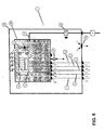
- Figure 6 shows an integrated machine control module I according to the invention, which preferably includes double encapsulation, so that within an external cabinet 20 an internal cabinet 10 is located, wherein the machine control system's input/output units I/O are located, from which control cables L1...Ln are arranged to the controlled equipment.
- the machine control system's process control units PCS may also be located in the internal cabinet, but these may also be located in a separate assembly compartment outside the basic unit assembly groups of the papermaking machine.
- the double encapsulation efficiently prevents the electronic components located in internal cabinet 10 from being exposed to ambient conditions. Hydraulic, pneumatic and electric equipment relating to the papermaking machine's automation may be located in the external cabinet 20 outside internal cabinet 10, possibly similarly protected, whereby they will be in the same mechanical assembly as the units of the machine control system.
- Lead-in of the cables required in the integrated machine control module I is arranged through tight lead-ins t into external cabinet 20 and further through leadins t' into internal cabinet 10.
- a power supply cable P, data communication bus C (system bus or I/O bus) and control cables L1...Ln for the controlled equipment are brought into the integrated machine control module I.
- I/O and process control units PCS are typically in the form of electronic cards, which are installed in electronics frame E.
- Electronics frame E within internal cabinet 10 is equipped with vibration dampers d, which protect units to be connected to electronics frame E against disturbing vibrations caused by the papermaking machine environment.
- supply channel 15 for trimming air is brought into internal cabinet 10, which channel supplies trimming air continuously into internal cabinet 10.
- the supply channel 15 for trimming air is equipped with a pressure reducer 16, which is used for regulating a suitable flow rate of trimming air.
- the air supplied to internal cabinet 10 flows through internal cabinet 10 and exits by way of fitting 25.
- the small airflow through internal cabinet 10 will remove moisture and other impurities entering the cabinet during maintenance.
- the flow-through causes a slight overpressure in external cabinet 20, whereby removal through condensation water exit opening 26 of water condensing in external cabinet 20 will become more efficient.
- a temperature detector 11 and a moisture detector 12 are located within internal cabinet 10 for use in monitoring that conditions within internal cabinet 10 will remain suitable for the operation of the machine control system's units. Temperature and moisture detectors 11, 12 may be provided with transmitters, which send temperature and moisture data to the monitoring unit. In case permissible temperature and moisture limits are exceeded, the papermaking machine's monitoring system will receive an alarm. Typically, leaving the door of the integrated machine control module I open will result in an alarm.
- the invention relates to a method for controlling a papermaking machine/board machine/tissue machine or such, which papermaking machine/board machine/tissue machine or such includes basic unit assembly groups, such as a headbox, a wire section, a press, a drying section, a coating unit, a finishing machine, etc.
- the machine control system of the papermaking machine/board machine/tissue machine or such comprises a central processing unit (e.g; a unit for control room, alarm and other such functions), one or more process control units, and one or more input/output units, which are connected by control cables to the controlled units or actuators.
- the process control units and/or input/output units of the machine control system are located in a mechanical machine part in connection with basic unit assembly groups of the papermaking machine/board machine/tissue machine or such.
- the invention also relates to an integrated machine control module in the machine control system of a papermaking machine/board machine/tissue machine or such.
- the integrated machine control module comprises an internal cabinet, wherein the process control units and/or the input/output units of the machine control system are located.
- Said internal cabinet equipment is arranged for monitoring ambient conditions as well as equipment for removing stresses caused by ambient conditions in such a way that the integrated machine control module can be located in ambient conditions existing in connection with basic unit assembly groups of the papermaking machine.
Landscapes
- Paper (AREA)
Abstract
Description
The invention relates to a method for controlling a papermaking machine/board machine/tissue machine or such, which papermaking machine/board machine/tissue machine or such includes basic unit assembly groups, such as a headbox, a wire section, a press, a drying section, a coating unit, a finishing machine, etc. The machine control system of the papermaking machine/board machine/tissue machine or such comprises a central processing unit (e.g; a unit for control room, alarm and other such functions), one or more process control units, and one or more input/output units, which are connected by control cables to the controlled units or actuators. In the method the process control units and/or input/output units of the machine control system are located in a mechanical machine part in connection with basic unit assembly groups of the papermaking machine/board machine/tissue machine or such.
Claims (15)
- A method of controlling a papermaking machine, board machine or tissue machine, which papermaking machine, board machine or tissue machine includes basic unit assembly groups (U1...Un), such as a headbox, a wire section, a press, a drying section, a coating unit or a finishing machine, and wherein a machine control system of the papermaking machine, board machine or tissue machine includes a central processing unit (CPU), one or more process control units (PCS) connected to said central processing unit (CPU), and one or more input/output units (I/O), connected by control cables (L1... Ln) to the controlled units or actuators (D11... D1m; Dn1 ... Dnm), comprising the steps of:connecting said process control units (PCS) located in connection with said basic unit assembly groups (U1 ... Un) of said papermaking machine to one another by a data communication bus (C),connecting said input/output units (I/O) located in connection with said basic unit assembly groups (U1 ... Un) of said papermaking machine to said process control unit (PCS) by a data communication bus (C'),housing the process control units (PCS) and/or the input/output units of the machine control system in an internal cabinet,locating said process control units (PCS) and/or input/output units (I/O) of the machine control system within a mechanical machine part in the basic unit assembly groups of the papermakingmachine, board machine or tissue machine, and locating said process control units (PCS) and/or said input/output units (I/O) in connection with basic unit assembly groups (U1 ... Un) of said papermaking machine in a same compartment as hydraulics, pneumatics, electricity, or vibration control automation,monitoring ambient conditions within the cabinet,protecting said process control units (PCS) and/or said input/output units (I/O) against ambient conditions, such as temperature variations, vibration, moisture and impurities by protective encapsulation and connecting said control cables (L1 ... Ln) with said input/output units (I/O) at a paper machine plant, andremoving stresses caused by said ambient conditions in such a way so that said integrated machine control module (I) is located in ambient conditions existing in connection with basic unit assembly groups of said papermaking machine.
- The method as defined in claim 1, further comprising the step of:connecting said process control units (PCS) and said input/output units (I/O) located in connection with basic unit assembly groups (U1 ... Un) of said papermaking machine to at least one of a remaining machine control system through a data communication bus (C).
- A machine control system of a papermaking machine, board machine or tissue machine, which papermarking machine, board machine or tissue machine includes basic unit assembly groups (U1 ... Un), such as a headbox, a wire section, a press a drying section, a coating unit or a finishing machine, and wherein the machine control system includes an integrated machine control module, which machine control system includes a central processing unit (CPU), one or more process control units (PCS) connected to said central processing unit (CPU), and one or more input/output units (I/O), connected by control cables (L1 ... Ln) to the controlled units or actuators (D11 ... D1m; Dn1 ... Dnm), wherein data communication connections (C) are between the central processing unit (CPU), the process control units (PCS) and the input/output units (I/O), said process control units (PCS) and/or input/output units (I/O) of the machine control system being located within a mechanical machine part in the basic unit assembly groups of the papermaking machine, board machine or tissue machine, being located in connection with basic unit assembly groups (U1 ... Un) of said papermaking machine in a same compartment as hydraulics, pneumatics, electricity, or vibration control automation and being protected against ambient conditions by protective encapsulation, wherein the integrated machine control module comprises :an internal cabinet (10) for housing said process control units (PCS) and/or said input/output units (I/O) of said machine control system therein;monitoring means structured and arranged within said internal cabinet (10) for monitoring ambient conditions within said cabinet, andstress removing means for removing stresses caused by said ambient conditions in such a way so that said integrated machine control module (I) is located in ambient conditions existing in connection with basic unit assembly groups of said papermaking machine.
- The machine control system as defined in claim 3, wherein said process control units (PCS) and/or said input/output units (I/O) of said machine control system are attached to an electronics frame (E).
- The machine control system as defined in claim 4 wherein said electronics frame (E) is protected by vibration dampers (d).
- The machine control system as defined in claim 3, further comprising:a temperature, moisture and/or vibration detector (11) structured and arranged within said internal cabinet (10).
- The machine control system as defined in claim 3, further comprising:a pressure detector (12) structured and arranged in said internal cabinet (10).
- The machine control system as defined in claim 3, further comprising:a flow-through of trimming air structured and arranged in said internal cabinet (10).
- The machine control system as defined in claim 8, further wherein said trimming air is brought into said internal cabinet (10) through a supply channel (15).
- The machine control system as defined in claim 9, further comprising:a pressure regulator (16) connected to said supply channel (15) in order to regulate the flow rate of the trimming air.
- The machine control system as defined in claim 3, further comprising:a plurality of tight cable lead-ins (t') for a power supply cable (P), for control cables (L1... Ln) of said equipment to be controlled by said machine control system and for said data communication bus cable (C) arranged within said internal cabinet (10).
- The machine control system as defined in claim 3, further comprising:a trimming air flow detector (12) for monitoring and ensuring that a door of said internal cabinet (10) remains closed.
- The machine control system as defined in claim 3, wherein said internal cabinet (10) is located within an external cabinet (20).
- The machine control system as defined in claim 13, wherein said external cabinet (20) further comprises:a condensation water removal system (26).
- The machine control system as defined in claim 13, further comprising:a plurality of tight cable lead-ins (t) structured and arranged in said external cabinet (20) for passage of a power supply cable (P), a plurality of control cables (L1... Ln) of said equipment to be controlled by said machine control system and for a data communication bus cable (C).
Applications Claiming Priority (4)
| Application Number | Priority Date | Filing Date | Title |
|---|---|---|---|
| FI992199A FI106477B (en) | 1999-10-13 | 1999-10-13 | Paper making machine control method involves providing central processing unit for machine control and connection of process control units and input/output unit with basic unit assembly groups |
| FI992199 | 1999-10-13 | ||
| FI992200A FI106478B (en) | 1999-10-13 | 1999-10-13 | Paper making machine control method involves providing central processing unit for machine control and connection of process control units and input/output unit with basic unit assembly groups |
| FI992200 | 1999-10-13 |
Publications (3)
| Publication Number | Publication Date |
|---|---|
| EP1092806A2 EP1092806A2 (en) | 2001-04-18 |
| EP1092806A3 EP1092806A3 (en) | 2002-06-26 |
| EP1092806B1 true EP1092806B1 (en) | 2005-03-16 |
Family
ID=26160786
Family Applications (1)
| Application Number | Title | Priority Date | Filing Date |
|---|---|---|---|
| EP00122186A Expired - Lifetime EP1092806B1 (en) | 1999-10-13 | 2000-10-12 | Method and device for controlling a papermaking machine |
Country Status (6)
| Country | Link |
|---|---|
| US (1) | US6482296B1 (en) |
| EP (1) | EP1092806B1 (en) |
| JP (1) | JP3629419B2 (en) |
| AT (1) | ATE291121T1 (en) |
| CA (1) | CA2323244C (en) |
| DE (1) | DE60018670T2 (en) |
Families Citing this family (6)
| Publication number | Priority date | Publication date | Assignee | Title |
|---|---|---|---|---|
| DE20000919U1 (en) * | 2000-01-20 | 2000-03-09 | MAN Roland Druckmaschinen AG, 63075 Offenbach | Monitoring device for a printing press |
| US6819970B2 (en) * | 2002-09-27 | 2004-11-16 | Ludowici Packaging Limited | Continuous path moulding machine |
| FI120000B (en) * | 2005-06-10 | 2009-05-29 | Metso Paper Inc | Installation module for a paper or cardboard machine |
| FI123370B (en) | 2007-11-07 | 2013-03-15 | Metso Paper Inc | A method for controlling circulation lubrication and circulation lubrication systems |
| CN105437520B (en) * | 2015-11-17 | 2017-10-24 | 贾军琪 | Agricultural film produces breadth automatic controller |
| CN106647243A (en) * | 2017-01-06 | 2017-05-10 | 蚌埠凯盛工程技术有限公司 | Automatic control system for air valve of calender |
Family Cites Families (11)
| Publication number | Priority date | Publication date | Assignee | Title |
|---|---|---|---|---|
| US3925679A (en) * | 1973-09-21 | 1975-12-09 | Westinghouse Electric Corp | Modular operating centers and methods of building same for use in electric power generating plants and other industrial and commercial plants, processes and systems |
| EP0234518A3 (en) * | 1986-02-28 | 1988-09-21 | Thermo Electron-Web Systems, Inc. | Improved system for controlling a web property profiling apparatus |
| US4730492A (en) * | 1986-05-12 | 1988-03-15 | Accuray Corporation | Measuring the speed of ultrasound in a moving web of paper |
| FI85731C (en) * | 1989-06-01 | 1997-08-20 | Valmet Paper Machinery Inc | Control system in a paper or cardboard machine |
| JP2711285B2 (en) * | 1989-06-03 | 1998-02-10 | 株式会社イソワ | Corrugator line distributed control method |
| JP3254714B2 (en) * | 1992-03-10 | 2002-02-12 | 石川島播磨重工業株式会社 | Method and apparatus for controlling calender roll gap |
| US5950693A (en) * | 1993-04-28 | 1999-09-14 | Advanced Delivery & Chemical Systems, Ltd. | Bulk chemical delivery system |
| US5833364A (en) * | 1993-11-17 | 1998-11-10 | Calgon Corporation | Chemical delivery and on-site blending system for producing multiple products |
| US5822208A (en) * | 1994-04-12 | 1998-10-13 | Bay Instrumentation & Technology Co. | Method and apparatus for predicting errors in a manufacturing process |
| US5421961A (en) * | 1994-09-26 | 1995-06-06 | Miller; Joseph | Forming board position control system |
| US5771174A (en) * | 1995-12-21 | 1998-06-23 | Measurex Corporation | Distributed intelligence actuator controller with peer-to-peer actuator communication |
-
2000
- 2000-10-12 CA CA002323244A patent/CA2323244C/en not_active Expired - Fee Related
- 2000-10-12 AT AT00122186T patent/ATE291121T1/en active
- 2000-10-12 EP EP00122186A patent/EP1092806B1/en not_active Expired - Lifetime
- 2000-10-12 DE DE60018670T patent/DE60018670T2/en not_active Expired - Lifetime
- 2000-10-13 US US09/687,888 patent/US6482296B1/en not_active Expired - Fee Related
- 2000-10-13 JP JP2000314102A patent/JP3629419B2/en not_active Expired - Fee Related
Also Published As
| Publication number | Publication date |
|---|---|
| DE60018670D1 (en) | 2005-04-21 |
| EP1092806A2 (en) | 2001-04-18 |
| ATE291121T1 (en) | 2005-04-15 |
| DE60018670T2 (en) | 2006-05-11 |
| JP3629419B2 (en) | 2005-03-16 |
| CA2323244C (en) | 2008-01-08 |
| US6482296B1 (en) | 2002-11-19 |
| JP2001164489A (en) | 2001-06-19 |
| CA2323244A1 (en) | 2001-04-13 |
| EP1092806A3 (en) | 2002-06-26 |
Similar Documents
| Publication | Publication Date | Title |
|---|---|---|
| KR100667991B1 (en) | Integrated Control Platform for Injection Molding Systems | |
| CA2066743C (en) | Field-mounted control unit | |
| KR100363456B1 (en) | A system for monitoring and regulating the circulating lubrication of cylinders and roller bearings in paper machines | |
| DK167481B1 (en) | PRINTING MACHINE WITH AT LEAST ONE PRESSURE | |
| US6482296B1 (en) | Integrated machine control method and machine control module | |
| GB2378298A (en) | System for locating control units | |
| KR100738356B1 (en) | Method and apparatus for locally processing casting data in measurement data obtained via sensors in a continuous casting die | |
| US20090027189A1 (en) | System for controlling an automation process | |
| US20030212529A1 (en) | Modular monitoring and protection system topology | |
| WO2009095546A2 (en) | A method for controlling a process and for monitoring the condition of process equipment, and an automation system | |
| CN101198826A (en) | Smart fan assisted tile for adaptive environmental management | |
| US5258652A (en) | Distributed plant control system | |
| CN1287933C (en) | Feed opening adjustment of segments for continuous casting systems | |
| US6035247A (en) | Distribution panel switch gear and monitoring and control system having distribution panel switch gear | |
| EP1579959B1 (en) | Intelligent tightening spindle with integrated measurement transducer, servo amplifier, and data processing unit | |
| CN107121968A (en) | System is adjusted using the production of disaster information | |
| FI106477B (en) | Paper making machine control method involves providing central processing unit for machine control and connection of process control units and input/output unit with basic unit assembly groups | |
| FI106478B (en) | Paper making machine control method involves providing central processing unit for machine control and connection of process control units and input/output unit with basic unit assembly groups | |
| FI123370B (en) | A method for controlling circulation lubrication and circulation lubrication systems | |
| ZA200404191B (en) | Feed opening adjustment of segments for continuous casting systems | |
| JPH01282603A (en) | Operation monitoring method and operation monitor | |
| Byrne | Alternator control system for the Alcator C-MOD tokamak | |
| DE102023106322A1 (en) | Field device system, method for adjusting a process fluid flow of a process engineering plant and process engineering plant | |
| KR20260072086A (en) | Automation process operation management system and method | |
| CN118705721A (en) | Industrial air conditioning anomaly detection method, system and storage medium based on AI |
Legal Events
| Date | Code | Title | Description |
|---|---|---|---|
| PUAI | Public reference made under article 153(3) epc to a published international application that has entered the european phase |
Free format text: ORIGINAL CODE: 0009012 |
|
| AK | Designated contracting states |
Kind code of ref document: A2 Designated state(s): AT BE CH CY DE DK ES FI FR GB GR IE IT LI LU MC NL PT SE |
|
| AX | Request for extension of the european patent |
Free format text: AL;LT;LV;MK;RO;SI |
|
| RAP1 | Party data changed (applicant data changed or rights of an application transferred) |
Owner name: METSO PAPER, INC. |
|
| PUAL | Search report despatched |
Free format text: ORIGINAL CODE: 0009013 |
|
| AK | Designated contracting states |
Kind code of ref document: A3 Designated state(s): AT BE CH CY DE DK ES FI FR GB GR IE IT LI LU MC NL PT SE |
|
| AX | Request for extension of the european patent |
Free format text: AL;LT;LV;MK;RO;SI |
|
| 17P | Request for examination filed |
Effective date: 20020823 |
|
| AKX | Designation fees paid |
Designated state(s): AT BE CH CY DE DK ES FI FR GB GR IE IT LI LU MC NL PT SE |
|
| 17Q | First examination report despatched |
Effective date: 20030403 |
|
| GRAP | Despatch of communication of intention to grant a patent |
Free format text: ORIGINAL CODE: EPIDOSNIGR1 |
|
| GRAS | Grant fee paid |
Free format text: ORIGINAL CODE: EPIDOSNIGR3 |
|
| GRAA | (expected) grant |
Free format text: ORIGINAL CODE: 0009210 |
|
| AK | Designated contracting states |
Kind code of ref document: B1 Designated state(s): AT BE CH CY DE DK ES FI FR GB GR IE IT LI LU MC NL PT SE |
|
| PG25 | Lapsed in a contracting state [announced via postgrant information from national office to epo] |
Ref country code: IT Free format text: LAPSE BECAUSE OF FAILURE TO SUBMIT A TRANSLATION OF THE DESCRIPTION OR TO PAY THE FEE WITHIN THE PRESCRIBED TIME-LIMIT;WARNING: LAPSES OF ITALIAN PATENTS WITH EFFECTIVE DATE BEFORE 2007 MAY HAVE OCCURRED AT ANY TIME BEFORE 2007. THE CORRECT EFFECTIVE DATE MAY BE DIFFERENT FROM THE ONE RECORDED. Effective date: 20050316 Ref country code: NL Free format text: LAPSE BECAUSE OF FAILURE TO SUBMIT A TRANSLATION OF THE DESCRIPTION OR TO PAY THE FEE WITHIN THE PRESCRIBED TIME-LIMIT Effective date: 20050316 Ref country code: FI Free format text: LAPSE BECAUSE OF FAILURE TO SUBMIT A TRANSLATION OF THE DESCRIPTION OR TO PAY THE FEE WITHIN THE PRESCRIBED TIME-LIMIT Effective date: 20050316 Ref country code: LI Free format text: LAPSE BECAUSE OF FAILURE TO SUBMIT A TRANSLATION OF THE DESCRIPTION OR TO PAY THE FEE WITHIN THE PRESCRIBED TIME-LIMIT Effective date: 20050316 Ref country code: CH Free format text: LAPSE BECAUSE OF FAILURE TO SUBMIT A TRANSLATION OF THE DESCRIPTION OR TO PAY THE FEE WITHIN THE PRESCRIBED TIME-LIMIT Effective date: 20050316 Ref country code: BE Free format text: LAPSE BECAUSE OF FAILURE TO SUBMIT A TRANSLATION OF THE DESCRIPTION OR TO PAY THE FEE WITHIN THE PRESCRIBED TIME-LIMIT Effective date: 20050316 |
|
| REG | Reference to a national code |
Ref country code: GB Ref legal event code: FG4D |
|
| REG | Reference to a national code |
Ref country code: CH Ref legal event code: EP |
|
| REG | Reference to a national code |
Ref country code: IE Ref legal event code: FG4D |
|
| REF | Corresponds to: |
Ref document number: 60018670 Country of ref document: DE Date of ref document: 20050421 Kind code of ref document: P |
|
| REG | Reference to a national code |
Ref country code: SE Ref legal event code: TRGR |
|
| PG25 | Lapsed in a contracting state [announced via postgrant information from national office to epo] |
Ref country code: DK Free format text: LAPSE BECAUSE OF FAILURE TO SUBMIT A TRANSLATION OF THE DESCRIPTION OR TO PAY THE FEE WITHIN THE PRESCRIBED TIME-LIMIT Effective date: 20050616 Ref country code: GR Free format text: LAPSE BECAUSE OF FAILURE TO SUBMIT A TRANSLATION OF THE DESCRIPTION OR TO PAY THE FEE WITHIN THE PRESCRIBED TIME-LIMIT Effective date: 20050616 |
|
| PG25 | Lapsed in a contracting state [announced via postgrant information from national office to epo] |
Ref country code: ES Free format text: LAPSE BECAUSE OF FAILURE TO SUBMIT A TRANSLATION OF THE DESCRIPTION OR TO PAY THE FEE WITHIN THE PRESCRIBED TIME-LIMIT Effective date: 20050627 |
|
| NLV1 | Nl: lapsed or annulled due to failure to fulfill the requirements of art. 29p and 29m of the patents act | ||
| PG25 | Lapsed in a contracting state [announced via postgrant information from national office to epo] |
Ref country code: PT Free format text: LAPSE BECAUSE OF FAILURE TO SUBMIT A TRANSLATION OF THE DESCRIPTION OR TO PAY THE FEE WITHIN THE PRESCRIBED TIME-LIMIT Effective date: 20050907 |
|
| REG | Reference to a national code |
Ref country code: CH Ref legal event code: PL |
|
| PG25 | Lapsed in a contracting state [announced via postgrant information from national office to epo] |
Ref country code: IE Free format text: LAPSE BECAUSE OF NON-PAYMENT OF DUE FEES Effective date: 20051012 Ref country code: CY Free format text: LAPSE BECAUSE OF FAILURE TO SUBMIT A TRANSLATION OF THE DESCRIPTION OR TO PAY THE FEE WITHIN THE PRESCRIBED TIME-LIMIT Effective date: 20051012 Ref country code: GB Free format text: LAPSE BECAUSE OF NON-PAYMENT OF DUE FEES Effective date: 20051012 |
|
| PG25 | Lapsed in a contracting state [announced via postgrant information from national office to epo] |
Ref country code: MC Free format text: LAPSE BECAUSE OF NON-PAYMENT OF DUE FEES Effective date: 20051031 Ref country code: LU Free format text: LAPSE BECAUSE OF NON-PAYMENT OF DUE FEES Effective date: 20051031 |
|
| PLBE | No opposition filed within time limit |
Free format text: ORIGINAL CODE: 0009261 |
|
| STAA | Information on the status of an ep patent application or granted ep patent |
Free format text: STATUS: NO OPPOSITION FILED WITHIN TIME LIMIT |
|
| 26N | No opposition filed |
Effective date: 20051219 |
|
| EN | Fr: translation not filed | ||
| GBPC | Gb: european patent ceased through non-payment of renewal fee |
Effective date: 20051012 |
|
| REG | Reference to a national code |
Ref country code: IE Ref legal event code: MM4A |
|
| PG25 | Lapsed in a contracting state [announced via postgrant information from national office to epo] |
Ref country code: FR Free format text: LAPSE BECAUSE OF NON-PAYMENT OF DUE FEES Effective date: 20051031 |
|
| PG25 | Lapsed in a contracting state [announced via postgrant information from national office to epo] |
Ref country code: FR Free format text: LAPSE BECAUSE OF NON-PAYMENT OF DUE FEES Effective date: 20050316 |
|
| PGFP | Annual fee paid to national office [announced via postgrant information from national office to epo] |
Ref country code: SE Payment date: 20131022 Year of fee payment: 14 Ref country code: AT Payment date: 20131011 Year of fee payment: 14 |
|
| REG | Reference to a national code |
Ref country code: SE Ref legal event code: EUG |
|
| REG | Reference to a national code |
Ref country code: AT Ref legal event code: MM01 Ref document number: 291121 Country of ref document: AT Kind code of ref document: T Effective date: 20141012 |
|
| PG25 | Lapsed in a contracting state [announced via postgrant information from national office to epo] |
Ref country code: SE Free format text: LAPSE BECAUSE OF NON-PAYMENT OF DUE FEES Effective date: 20141013 |
|
| PG25 | Lapsed in a contracting state [announced via postgrant information from national office to epo] |
Ref country code: AT Free format text: LAPSE BECAUSE OF NON-PAYMENT OF DUE FEES Effective date: 20141012 |
|
| PGFP | Annual fee paid to national office [announced via postgrant information from national office to epo] |
Ref country code: DE Payment date: 20181019 Year of fee payment: 19 |
|
| REG | Reference to a national code |
Ref country code: DE Ref legal event code: R119 Ref document number: 60018670 Country of ref document: DE |
|
| PG25 | Lapsed in a contracting state [announced via postgrant information from national office to epo] |
Ref country code: DE Free format text: LAPSE BECAUSE OF NON-PAYMENT OF DUE FEES Effective date: 20200501 |