EP1092802A2 - Washing and/or drying machine, with element for protecting against water penetration - Google Patents
Washing and/or drying machine, with element for protecting against water penetration Download PDFInfo
- Publication number
- EP1092802A2 EP1092802A2 EP00203527A EP00203527A EP1092802A2 EP 1092802 A2 EP1092802 A2 EP 1092802A2 EP 00203527 A EP00203527 A EP 00203527A EP 00203527 A EP00203527 A EP 00203527A EP 1092802 A2 EP1092802 A2 EP 1092802A2
- Authority
- EP
- European Patent Office
- Prior art keywords
- cabinet
- machine
- protection element
- opening
- packing
- Prior art date
- Legal status (The legal status is an assumption and is not a legal conclusion. Google has not performed a legal analysis and makes no representation as to the accuracy of the status listed.)
- Withdrawn
Links
- XLYOFNOQVPJJNP-UHFFFAOYSA-N water Substances O XLYOFNOQVPJJNP-UHFFFAOYSA-N 0.000 title claims abstract description 33
- 238000005406 washing Methods 0.000 title claims abstract description 23
- 238000001035 drying Methods 0.000 title claims abstract description 13
- 230000035515 penetration Effects 0.000 title description 11
- 238000012856 packing Methods 0.000 claims description 29
- 238000000034 method Methods 0.000 claims description 9
- 239000000463 material Substances 0.000 claims description 8
- 230000008878 coupling Effects 0.000 claims description 6
- 238000010168 coupling process Methods 0.000 claims description 6
- 238000005859 coupling reaction Methods 0.000 claims description 6
- 238000010412 laundry washing Methods 0.000 claims description 6
- 238000003780 insertion Methods 0.000 claims description 4
- 230000037431 insertion Effects 0.000 claims description 4
- 239000004033 plastic Substances 0.000 claims description 4
- 229920006248 expandable polystyrene Polymers 0.000 claims description 3
- 230000000284 resting effect Effects 0.000 claims description 3
- 230000000452 restraining effect Effects 0.000 claims 2
- 230000002093 peripheral effect Effects 0.000 claims 1
- 230000000630 rising effect Effects 0.000 claims 1
- 238000012360 testing method Methods 0.000 description 7
- 238000004519 manufacturing process Methods 0.000 description 6
- 238000001816 cooling Methods 0.000 description 5
- 239000002184 metal Substances 0.000 description 5
- 238000004806 packaging method and process Methods 0.000 description 3
- 238000009434 installation Methods 0.000 description 2
- 239000004793 Polystyrene Substances 0.000 description 1
- 230000006978 adaptation Effects 0.000 description 1
- 239000011230 binding agent Substances 0.000 description 1
- 238000011161 development Methods 0.000 description 1
- 238000004851 dishwashing Methods 0.000 description 1
- 238000006073 displacement reaction Methods 0.000 description 1
- 230000010354 integration Effects 0.000 description 1
- 239000007769 metal material Substances 0.000 description 1
- 238000000465 moulding Methods 0.000 description 1
- NJPPVKZQTLUDBO-UHFFFAOYSA-N novaluron Chemical compound C1=C(Cl)C(OC(F)(F)C(OC(F)(F)F)F)=CC=C1NC(=O)NC(=O)C1=C(F)C=CC=C1F NJPPVKZQTLUDBO-UHFFFAOYSA-N 0.000 description 1
- 238000013021 overheating Methods 0.000 description 1
- 238000011056 performance test Methods 0.000 description 1
- 238000007747 plating Methods 0.000 description 1
- 229920002223 polystyrene Polymers 0.000 description 1
- 125000006850 spacer group Chemical group 0.000 description 1
Images


Classifications
-
- D—TEXTILES; PAPER
- D06—TREATMENT OF TEXTILES OR THE LIKE; LAUNDERING; FLEXIBLE MATERIALS NOT OTHERWISE PROVIDED FOR
- D06F—LAUNDERING, DRYING, IRONING, PRESSING OR FOLDING TEXTILE ARTICLES
- D06F39/00—Details of washing machines not specific to a single type of machines covered by groups D06F9/00 - D06F27/00
- D06F39/12—Casings; Tubs
Definitions
- the present invention relates to a washing and/or drying machines in particular for laundry, comprising a cabinet and electric components located within said cabinet.
- washing machines comprise, within their relevant cabinets, electric components, which have to be adequately protected against water penetration or sprinkling.
- a machine is submitted to artificial rain for a predetermined time, during which the machine is placed on a pedestal in its usual working position and is invested with a plurality of continuous water jets; at the end of the test, the inside of the machine cabinet is checked, to ascertain whether any water has reached electric components.
- the aim of these capability tests is to avoid endangering users' safety, due to water penetration from outside, such as in the event of water being accidentally spilled over the machine or on the floor of the room where the machine is installed.
- a number of the above electric components is generally arranged in the upper part of the machine cabinet, in correspondence with a control panel; the protection of these electric components against possible water penetration is usually obtained through a special execution, being per se known, of the same control panel and/or of the top of the machine cabinet, or by means of appropriate guards, manufactured for this specific purpose and assembled inside the machine cabinet.
- the cabinets of the laundry washing and/or drying machines have an open bottom; this is due to the particular manufacturing of the cabinet, which is obtained from a single metal plating, being is appropriately C-shaped to form a front wall and two side walls; a wall screwed on the rear edges of both side walls is then provided, for closing and protecting the cabinet rear side; finally, the upper part of the cabinet is completed by means of a appropriate top, being fastened according to common procedures.
- supporting feet are also present, whose height is adjustable for ensuring the most exact positioning or leveling of the machine as possible, should the floor whereon the machine is installed be slightly uneven or somewhat slanted.
- the above embodiment prevents water from outside the machine to reach the electric components within the cabinet; substantially, this is allowed by the presence of the supporting feet, which keep the cabinet raised as a whole from the floor and, as said, by the fact that no electric components are installed just in correspondence with the cabinet bottom.
- the lower part of the machine cabinet has a proper fixed bottom wall, which is made integral directly with the cabinet vertical walls; in some instances, this bottom wall is made from metal material and is firmly screwed or welded to the vertical walls; in other instances, the bottom wall is made from plastic material and is firmly fastened to the above cabinet parts with screws.
- the above bottom wall does not rest directly on the floor of the room where the machine is installed, but is raised from it, due to the presence of the feet.
- the presence of a metal bottom wall requires a higher amount of material and, consequently, higher costs.
- Another problem of the prior art described above is that the provision of a bottom wall drastically reduces or even removes the possibility of air circulation and air exchange within the machine cabinet, which are required for cooling down the internal electric components; as a result, specific electric components have to be assembled, which are capable of operating at higher working temperatures than the ones which can be used on the machines with an open bottom, or have to be fitted with special heat dissipating means, which entails higher manufacturing costs.
- a further problem caused by a bottom wall may also arise in connection with the machine packing for transportation purposes.
- the above unit is at least partly anchored to the cabinet by means of springs and/or dampers, to let it oscillate to a certain degree during the rotation of the machine drum, in particular during the high speed rotation steps.
- the oscillating unit can be maintained in a substantially firm position, in its the upper portion, by means of special stirrups; in order to avoid any movements of the lower portion of the unit, in the instance of machines having an open bottom cabinet, an additional supporting element is provided, consisting of a polystyrene element of the machine packing; accordingly, the machine motor or other part of the oscillating unit can rest on this supporting element, which passes through the open bottom of the cabinet, thus removing any stress or motion of these components.
- both the packing ⁇ which is inclusive of the above additional supporting element ⁇ and the above stirrups are removed from the machine, to let said unit free to oscillate.
- the present invention has the aim of solving one or more of the above drawbacks.
- a first aim of the present invention is to provide a washing and/or drying machine, having a lower protection element for preventing water penetration from outside, which is cost effective, allows simple industrial manufacturing and can be easily applied also to a fully assembled machine, in particular without requiring complex assembly operations.
- a second aim of the present invention is to provide a machine as above, wherein the cited lower protection element does not hinder air circulation and air exchange within the cabinet, which are required for cooling down the machine internal electric components.
- a third aim of the present invention is to provide a machine as above, wherein the cited lower protection element anyway allows the use of a packing component for supporting the motor and/or the oscillating unit, for transportation purposes.
- One or more of the above aims, as well as further aims, arc reached according to the present invention by a washing and/or drying machine, as well as a method for packing and/or for the application of a protection element, incorporating the features of the annexed claims, which form an integral part of the present description.
- reference 1 indicates the cabinet of a washing machine as a whole, according to the teachings of the present invention, whose lower portion is only illustrated; in the example, this machine is a laundry washing and/or drying machine, but obviously the invention may also be applied to a dishwashing machine.
- the cabinet 1 is an open bottom cabinet, i.e. without a lower wall, and is substantially manufactured according to the known technique described at the beginning of the present description.
- Reference 2 indicates one of the side walls of the cabinet 1, whereas 3 and 4 indicate its front wall and rear wall, respectively; of course, the cabinet 1 also consists of a second side wall, which is not visible in the section of Fig. 1.
- Reference 5 indicates two of four supporting feet, which are substantially placed in correspondence with the lower corners of the cabinet 1, for maintaining the latter at a certain height from the floor P of the room where the machine is installed; as in the prior art, at least one of the feet 5 can be screwed and unscrewed in a threaded seat of the cabinet 1, for ensuring the exact leveling of the machine with respect to the floor P, also in the instance of an uneven or bad floor; by way of example, let us assume here that all feet 5 are of the adjustable type.
- Reference 6 indicates the lower edge of the side wall 2 of the cabinet 1, which is substantially C-shaped towards the inside of the cabinet 1; accordingly, 6A indicates the folded end of said wall 2; it should be noticed that also the lower edge of the second side wall of the cabinet 1 ⁇ not visible in the section of Fig. 1 - has a shape alike.
- Reference 6' indicates the lower edge of the wall 4 of the cabinet 1, which is also substantially C-shaped towards the inside of the cabinet 1, on which the threaded seats for two feet 5 are defined; 6A' indicates then the folded end of said wall 4; it should be noticed that also the lower edge of the wall 3 of the cabinet 1 has a shape alike.
- Reference 7 indicates a protection element, whose function is to prevent water penetration towards the inside of the cabinet 1, in the lower part of the latter.
- the protection element 7, which is illustrated with different views in Figs. 2, 3 and 4, is made from a single piece, preferably foamed polystyrene.
- the protection element 7 is shaped in its whole as a rectangular frame; from Fig. 4 it can be noticed how the section of the protection element 7 consists of a base 8, being substantially rectangular shaped, and of a projection 9 departing perpendicularly from said base 8.
- the projection 9 extends over the whole rectangular development of the base 8, in an intermediate position of the latter; in particular, Fig. 3 and 4 show how the projection 9 is recessed with respect to the outer edge of the sides of the element 7; in this way, a plane 10 is defined between the outer edge of the sides of the protection element and the projection 9.
- Fig. 3 shows how said protrusions 11 are configured in their upper part to delimit a tooth 12, facing towards the outside of the protection element 7; as it will be further cleared later, the teeth 12 are provided for engaging with the folded ends 6A of the walls 2.
- the overall dimensions of the protection element 7 are such to let the projection 9 enter the opening in the cabinet bottom 1, i.e. it can be substantially inserted flush with respect to the lower edges 6 and 6' of the walls 2, 3 and 4 delimiting said opening; the plane 10 of the protection element 7 (Fig. 3) practically forms a limit or stop element for the projection 9 entering the bottom opening of the cabinet 1, striking against such lower edges.
- the distance between the teeth 12 and the plane 10 is greater than the height of the folded end 6A of the walls 2 of the cabinet 1, so as to ensure a certain clearance for the movement downwards of the protection element 7 with respect to the cabinet itself; this clearance, in particular, always warrants the protection element 7 to rest on the floor P, in any leveling situation of the machine obtained through the feet 5.
- reference 13 indicates some grooves or passages, which passes across the section of the protection element 7; said passages 13 are appropriately shaped for preventing likely water jets coming from outside the protection element 7 to reach the inside of the same.
- the passages 13 are substantially herring-bone shaped, but other labyrinth sections can obviously be provided to the purpose.
- passages 13 allow air to flow, from outside the element 7 to the inside of the cabinet 1, through the bottom opening of the latter for cooling the internal electric components of the machine; however, as said above, the particular shape of the passages 13 is such to hinder water entry.
- the assembly of the protection element 7 on the cabinet 1 can be obtained in a fast and simply way, through elementary operations.
- the protrusions 11 may have their thickness reduced all over their height, e.g. having a vertical undercut, being indicated in the figures with 11A.
- the above engaging operation also causes the projection 9 to enter the opening on the cabinet bottom.
- the lower surface of the protection element 7 rests directly on the floor P; this is made possible by the clearance between the teeth 12 and the lower edge of the walls 2-4; this clearance is such to let the protection element 7 rest on the floor P also when adjusting the feet height 5.
- the height of the projection 9 is such that, even in the instance of a maximum downward displacement of the protection clement 7 (i.e. with the feet 5 being unscrewed to their utmost extent), the upper end of same projection 9 is always inserted in the bottom opening of the cabinet 1.
- Fig. 5 represents a possible adjustment condition of the leveling of the machine according to the present invention, should the floor P be slanted.
- the protection element 7 constantly rests on the floor P; as it can be understood, also in this event, since the projection 9 is anyway always inserted in the bottom opening of the cabinet 1, the protection element 7 prevents water penetration towards the inside of the cabinet 1; this notwithstanding, the passages 12 anyway ensures the necessary circulation of the cooling air.
- the protection element 7 may eventually be performed directly on the assembly line, at the end of the manufacturing stage of the machine according to the present invention; however, according to a preferred embodiment of the present invention, the protection element 7 may also act as a packing component of the machine and be automatically assembled on the cabinet 1 during the packing stages of the machine.
- the protection element 7 can be placed on the basement of a standard packing of a washing machine, preferably in a suitable seat defined in the basement itself, so that both parts integrate with each other.
- the protrusions 11 of the protection element 7 are automatically inserted in the bottom opening of the cabinet 1, according to the same procedures previously described.
- the protection element 7 can eventually also be used as a supporting component of the machine cabinet within the packing; in fact, following the above coupling, the lower edges 6 and 6' of the walls 2-4 of the cabinet 1 rest on the four planes 10 defined in the protection element 7.
- the element 7 performs a function being additional with respect to the protecting functions against water penetration, and its assembly is obtained practically in an automatic way during its packaging.
- the protection element 7 can be made from foamed polystyrene, which is the same basic material normally utilized for various packing components (such as cross-bars, basement, spacers, etc.); on the other hand, the material utilized for the protection element 7 will possibly have a higher density than the one used for common packing components, since the former shall have enough elasticity to let the protrusions 11 flex without breaking.
- Figs. 6 and 7 illustrate, in fact, a possible variant embodiment of the protection element provided by the washing machine according to the present invention, through which the above advantages can also be reached.
- this protection element has a rectangular frame configuration and can be obtained as a single piece from plastic material.
- the element 7' defines a base or lower part 8', whose external surfaces are at least partially inclined; a flange 10' facing outside is provided on the top of this base 8'; a wall or baffle 10'' facing downwards is defined on the outer edge of the flange 10'.
- the protection element 7' does not include in this instance the projection 9 of the previous embodiment according to Figs. 1-5; vice-versa, local projections indicated with 9' are provided, performing a centering function, which depart upwards from the flange 10', near the outer edge of the latter.
- protrusions 11' are also departing, which are so configured in their upper part for defining a tooth 12' facing outside the protection element 7'; the teeth 12' are provided for coupling with the folded ends 6A of the walls 2 of the washing machine cabinet (Figs. 1 and 5).
- the protection element 7' has smaller external overall dimensions than the protection element 7 of Figs. 1-5, or anyway they are such to have the flange 10' recessed with respect to the opening delimited on the lower end of the machine cabinet; this notwithstanding, the size of the element 7' is such that the projections 9' and the protrusions 11' can enter said lower opening of the cabinet 1.
- the length of the protrusions 11' bearing the teeth 12' allows a certain clearance in the downwards movement of the protection element 7', with respect to the machine cabinet; this clearance, in particular, always warrants a support for the protection element 7' on the floor P, in any leveling situation of the machine obtained by means of the feet 5.
- reference 13' in Figs. 6 and 7 indicates some passages, which pass through the section of the flange 10' and are appropriately realized to prevent possible water jets from outside the protection element 7' from reaching the inside of the latter.
- the position of such passages 13' which have a vertical axis and are defined in a horizontal surface (such as the flange 10') raised with respect to the floor, is such to hinder water inlet within the passages themselves; the same applies for the baffle 10'', which forms a sort of screen to protect the passages 13' from possible front water sprinkling coming from the outside and/or occasional water streams running along the outer surfaces of the machine cabinet.
- the presence of the passages 13' allows the passage of air, from outside the element 7' to inside the cabinet 1 through the bottom opening of the latter, for the cooling of the internal electric components of the machine; however, as already said, the particular arrangement of the passages 13' and/or the presence of the baffle 10'' hinders water inlet.
- the assembly of the protection element 7' according to the suggested variant embodiment can be made in a simple and fast manner, through elementary operations.
- the above engaging operation also causes the insertion of the projections 9' within the opening on the cabinet bottom, which ensure a correct centering of the element 7'.
- the lower surface of the protection element 7' rests directly on the floor P, due to the clearance between the teeth 12' and the lower edge of the walls 2-4; this clearance is such that the protection element 7' rests on the floor P also in the case of adjusting the height of the feet 5.
- the protection element may have a bottom wall, for performing also the function of tray for collecting possible water leaks occurring within the machine cabinet; in this event, with reference to the embodiment of Figs. 1-5, the passages 13 will be defined at a higher height than said bottom wall, and suitable detecting means pertaining to an anti-flood safety system will be possibly positioned on said bottom wall, if required.
- the assembly of such a protection element should be performed directly at the user's, in order to allow the bottom opening of the cabinet to be anyway exploited for the packing component that supports the motor; however, also in this instance, the advantages offered by the present invention results in being significant when compared to the prior art, considering that the above assembly can anyway be obtained by simply inclining the machine cabinet on one side, for inserting the engaging protrusions 11 in the bottom opening.
- the engaging protrusions 11, 11' may be in a larger number and differently arranged with respect to what has been illustrated in the figures.
Landscapes
- Engineering & Computer Science (AREA)
- Textile Engineering (AREA)
- Main Body Construction Of Washing Machines And Laundry Dryers (AREA)
- Detail Structures Of Washing Machines And Dryers (AREA)
Abstract
- said cabinet (1) has feet (5) for standing on a plane (P), said feet (5) determining the presence of a space between the lower end of said cabinet (1) and said plane (P),
- an opening is defined on the bottom of said cabinet (1);
- a protection element (7') is associated underneath said cabinet (1), for avoiding water from outside said cabinet (1) to reach the inside of the latter through said opening.
Description
- The present invention relates to a washing and/or drying machines in particular for laundry, comprising a cabinet and electric components located within said cabinet.
- As known, washing machines comprise, within their relevant cabinets, electric components, which have to be adequately protected against water penetration or sprinkling.
- This need, dictated by safety requirements, is confirmed by specific Standards, the respect of which is a requisite for obtaining the necessary approvals and certifications for the sale of the appliances; to this purpose, for example, specific tests are provided by the approval institutes of some Countries, to check the protection level of a laundry washing and/or drying machine related to its electric components against possible water penetration from outside.
- According to these tests, a machine is submitted to artificial rain for a predetermined time, during which the machine is placed on a pedestal in its usual working position and is invested with a plurality of continuous water jets; at the end of the test, the inside of the machine cabinet is checked, to ascertain whether any water has reached electric components.
- The aim of these capability tests is to avoid endangering users' safety, due to water penetration from outside, such as in the event of water being accidentally spilled over the machine or on the floor of the room where the machine is installed.
- A number of the above electric components is generally arranged in the upper part of the machine cabinet, in correspondence with a control panel; the protection of these electric components against possible water penetration is usually obtained through a special execution, being per se known, of the same control panel and/or of the top of the machine cabinet, or by means of appropriate guards, manufactured for this specific purpose and assembled inside the machine cabinet.
- Other electric components, such as the motor typically used for operating the laundry drum and the inlet and outlet wash-water pumps, are vice-versa located in the lower part of the machine cabinet, at a certain distance from its lower end.
- In some instances, the cabinets of the laundry washing and/or drying machines have an open bottom; this is due to the particular manufacturing of the cabinet, which is obtained from a single metal plating, being is appropriately C-shaped to form a front wall and two side walls; a wall screwed on the rear edges of both side walls is then provided, for closing and protecting the cabinet rear side; finally, the upper part of the cabinet is completed by means of a appropriate top, being fastened according to common procedures.
- At the lower corners of the cabinet defined as above, supporting feet are also present, whose height is adjustable for ensuring the most exact positioning or leveling of the machine as possible, should the floor whereon the machine is installed be slightly uneven or somewhat slanted.
- Notwithstanding the presence of an open bottom, the above embodiment prevents water from outside the machine to reach the electric components within the cabinet; substantially, this is allowed by the presence of the supporting feet, which keep the cabinet raised as a whole from the floor and, as said, by the fact that no electric components are installed just in correspondence with the cabinet bottom.
- According to other known solutions, the lower part of the machine cabinet has a proper fixed bottom wall, which is made integral directly with the cabinet vertical walls; in some instances, this bottom wall is made from metal material and is firmly screwed or welded to the vertical walls; in other instances, the bottom wall is made from plastic material and is firmly fastened to the above cabinet parts with screws.
- Obviously, the above bottom wall does not rest directly on the floor of the room where the machine is installed, but is raised from it, due to the presence of the feet.
- The solution of providing a bottom wall for the machine cabinet, while increasing on the one hand the protection degree for the internal electric components of the machine against any accidental presence of water from outside, entails on the other hand some problems.
- For example, the presence of a metal bottom wall requires a higher amount of material and, consequently, higher costs.
- In addition, the fastening with screws of the bottom wall, either when made from metal or when made from plastic material, requires a specific operation during the machine manufacturing cycle, so considerably increasing the process times and costs; analogous consideration may ensue in the event a metal bottom wall is welded to the overhanging part of the machine cabinet.
- Another problem of the prior art described above is that the provision of a bottom wall drastically reduces or even removes the possibility of air circulation and air exchange within the machine cabinet, which are required for cooling down the internal electric components; as a result, specific electric components have to be assembled, which are capable of operating at higher working temperatures than the ones which can be used on the machines with an open bottom, or have to be fitted with special heat dissipating means, which entails higher manufacturing costs.
- A further problem caused by a bottom wall may also arise in connection with the machine packing for transportation purposes.
- It is known, in fact, that some components of a laundry washing and/or drying machine are elastically mounted within the relevant cabinet; typically, these elements form the so-called "oscillating unit", comprising at least :
- the machine washing tub, containing the laundry drum;
- the motor for producing the drum actuation, usually arranged at a lower height level with respect to the tub, and elastically anchored to the latter;
- metal pulleys, for transferring the rotation produced by the motor to the drum.
- The above unit is at least partly anchored to the cabinet by means of springs and/or dampers, to let it oscillate to a certain degree during the rotation of the machine drum, in particular during the high speed rotation steps.
- However, when handling the machine for its transportation, there is the necessity of avoiding the oscillating unit to perform excessive movements, and coming into contact with the cabinet or any fixed components associated to it, as this would possibly damage the parts.
- To this purpose, the oscillating unit can be maintained in a substantially firm position, in its the upper portion, by means of special stirrups; in order to avoid any movements of the lower portion of the unit, in the instance of machines having an open bottom cabinet, an additional supporting element is provided, consisting of a polystyrene element of the machine packing; accordingly, the machine motor or other part of the oscillating unit can rest on this supporting element, which passes through the open bottom of the cabinet, thus removing any stress or motion of these components.
- When installing the machine, i.e. after its transportation to the site, both the packing ― which is inclusive of the above additional supporting element ― and the above stirrups are removed from the machine, to let said unit free to oscillate.
- In the event of a machine with a fixed bottom wall, it is obvious that a portion of the packing cannot be directly used as a support for the motor or the oscillating unit; to this purpose, a special support and/or additional stirrups must be provided within the cabinet; this entails a cost increase and uncomfortable operations when preparing the machine for transportation and its subsequent installation.
- In the event of machines having a bottom wall screwed on, this wall can obviously be removed for transportation purposes, so as to utilize a packing element for supporting the motor; however, it is however also clear that this compromise solution makes the operations required for preparing the machine for transportation and subsequent installation more complicated.
- The present invention has the aim of solving one or more of the above drawbacks.
- Within this frame, a first aim of the present invention is to provide a washing and/or drying machine, having a lower protection element for preventing water penetration from outside, which is cost effective, allows simple industrial manufacturing and can be easily applied also to a fully assembled machine, in particular without requiring complex assembly operations.
- A second aim of the present invention is to provide a machine as above, wherein the cited lower protection element does not hinder air circulation and air exchange within the cabinet, which are required for cooling down the machine internal electric components.
- A third aim of the present invention is to provide a machine as above, wherein the cited lower protection element anyway allows the use of a packing component for supporting the motor and/or the oscillating unit, for transportation purposes.
- One or more of the above aims, as well as further aims, arc reached according to the present invention by a washing and/or drying machine, as well as a method for packing and/or for the application of a protection element, incorporating the features of the annexed claims, which form an integral part of the present description.
- Further aims, features and advantages of the present invention will become apparent from the following detailed description and annexed drawings, which are supplied by way of non limiting example, wherein:
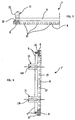
- Fig. 1 shows a schematic lengthwise section of the lower part of a washing machine being realized according to the teachings of the present invention.
- Fig 2 shows a schematic view from the bottom of a lower protection element pertaining to the washing machine according to the present invention;
- Fig. 3 shows a partial section of the lower protection element, according to the axis I-I of Fig. 2;
- Fig. 4 shows a section of the lower protection element, according to the axis II-II of Fig. 2.
- Fig. 5 shows a schematic lengthwise section of the lower part of a washing machine being realized according to the teachings of the present invention, in the condition of an uneven plane whereon the machine is installed;
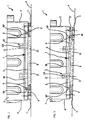
- Figs. 6 and 7 represent perspective views of a protection element realized according to a possible variant embodiment of the present invention.
- In Fig. 1, reference 1 indicates the cabinet of a washing machine as a whole, according to the teachings of the present invention, whose lower portion is only illustrated; in the example, this machine is a laundry washing and/or drying machine, but obviously the invention may also be applied to a dishwashing machine.
- The cabinet 1 is an open bottom cabinet, i.e. without a lower wall, and is substantially manufactured according to the known technique described at the beginning of the present description.
-
Reference 2 indicates one of the side walls of the cabinet 1, whereas 3 and 4 indicate its front wall and rear wall, respectively; of course, the cabinet 1 also consists of a second side wall, which is not visible in the section of Fig. 1. -
Reference 5 indicates two of four supporting feet, which are substantially placed in correspondence with the lower corners of the cabinet 1, for maintaining the latter at a certain height from the floor P of the room where the machine is installed; as in the prior art, at least one of thefeet 5 can be screwed and unscrewed in a threaded seat of the cabinet 1, for ensuring the exact leveling of the machine with respect to the floor P, also in the instance of an uneven or bad floor; by way of example, let us assume here that allfeet 5 are of the adjustable type. -
Reference 6 indicates the lower edge of theside wall 2 of the cabinet 1, which is substantially C-shaped towards the inside of the cabinet 1; accordingly, 6A indicates the folded end of saidwall 2; it should be noticed that also the lower edge of the second side wall of the cabinet 1 ― not visible in the section of Fig. 1 - has a shape alike. - Reference 6' indicates the lower edge of the wall 4 of the cabinet 1, which is also substantially C-shaped towards the inside of the cabinet 1, on which the threaded seats for two
feet 5 are defined; 6A' indicates then the folded end of said wall 4; it should be noticed that also the lower edge of thewall 3 of the cabinet 1 has a shape alike. -
Reference 7 indicates a protection element, whose function is to prevent water penetration towards the inside of the cabinet 1, in the lower part of the latter. - The
protection element 7, which is illustrated with different views in Figs. 2, 3 and 4, is made from a single piece, preferably foamed polystyrene. - As it can be noticed, in particular in Fig. 2, the
protection element 7 is shaped in its whole as a rectangular frame; from Fig. 4 it can be noticed how the section of theprotection element 7 consists of abase 8, being substantially rectangular shaped, and of aprojection 9 departing perpendicularly fromsaid base 8. - As it can be noticed, the
projection 9 extends over the whole rectangular development of thebase 8, in an intermediate position of the latter; in particular, Fig. 3 and 4 show how theprojection 9 is recessed with respect to the outer edge of the sides of theelement 7; in this way, aplane 10 is defined between the outer edge of the sides of the protection element and theprojection 9. - From the above figures it is also possible to notice how two
protrusions 11 depart upwards from each of the minor sides of theprotection element 7. - Fig. 3 shows how said
protrusions 11 are configured in their upper part to delimit atooth 12, facing towards the outside of theprotection element 7; as it will be further cleared later, theteeth 12 are provided for engaging with the foldedends 6A of thewalls 2. - The overall dimensions of the
protection element 7 are such to let theprojection 9 enter the opening in the cabinet bottom 1, i.e. it can be substantially inserted flush with respect to thelower edges 6 and 6' of thewalls plane 10 of the protection element 7 (Fig. 3) practically forms a limit or stop element for theprojection 9 entering the bottom opening of the cabinet 1, striking against such lower edges. - It should also be noticed that the distance between the
teeth 12 and theplane 10 is greater than the height of the foldedend 6A of thewalls 2 of the cabinet 1, so as to ensure a certain clearance for the movement downwards of theprotection element 7 with respect to the cabinet itself; this clearance, in particular, always warrants theprotection element 7 to rest on the floor P, in any leveling situation of the machine obtained through thefeet 5. - Finally, in the figures,
reference 13 indicates some grooves or passages, which passes across the section of theprotection element 7; saidpassages 13 are appropriately shaped for preventing likely water jets coming from outside theprotection element 7 to reach the inside of the same. - In the example of Fig. 2, the
passages 13 are substantially herring-bone shaped, but other labyrinth sections can obviously be provided to the purpose. - The presence of
passages 13 allow air to flow, from outside theelement 7 to the inside of the cabinet 1, through the bottom opening of the latter for cooling the internal electric components of the machine; however, as said above, the particular shape of thepassages 13 is such to hinder water entry. - As it can be imagined, the assembly of the
protection element 7 on the cabinet 1 can be obtained in a fast and simply way, through elementary operations. - To obtain this, in fact, it is enough to insert the
protrusions 11 of theprotection clement 7 inside the opening on the bottom of the cabinet 1. - This insertion can take place because the interference of the inclined side of the
teeth 12 with the lower part 6-6A of thecabinet side walls 2 causes a slight flexure of theprotrusions 11; it should be noticed that, in order to facilitate this flexure, theprotrusions 11 may have their thickness reduced all over their height, e.g. having a vertical undercut, being indicated in the figures with 11A. - When the inclined side of the
teeth 12 exceeds the upper edge of the foldedend 6A, theprotrusions 11 go flexibly back to their original position: in this way, the horizontal length of theteeth 12 now binders theprotection element 7 from coming off the lower opening of the cabinet 1. - Obviously, the above engaging operation also causes the
projection 9 to enter the opening on the cabinet bottom. - When the machine is then installed, the lower surface of the
protection element 7 rests directly on the floor P; this is made possible by the clearance between theteeth 12 and the lower edge of the walls 2-4; this clearance is such to let theprotection element 7 rest on the floor P also when adjusting thefeet height 5. - It should be noticed to this purpose that the height of the
projection 9 is such that, even in the instance of a maximum downward displacement of the protection clement 7 (i.e. with thefeet 5 being unscrewed to their utmost extent), the upper end ofsame projection 9 is always inserted in the bottom opening of the cabinet 1. - To this purpose, Fig. 5 represents a possible adjustment condition of the leveling of the machine according to the present invention, should the floor P be slanted.
- As it can be seen from this figure, even after a correct leveling of the machine (obtained by screwing the
foot 5 represented on the left and unscrewing thefoot 5 represented on the right), theprotection element 7 constantly rests on the floor P; as it can be understood, also in this event, since theprojection 9 is anyway always inserted in the bottom opening of the cabinet 1, theprotection element 7 prevents water penetration towards the inside of the cabinet 1; this notwithstanding, thepassages 12 anyway ensures the necessary circulation of the cooling air. The above assembly operations of theprotection element 7 to the cabinet 1 may eventually be performed directly on the assembly line, at the end of the manufacturing stage of the machine according to the present invention; however, according to a preferred embodiment of the present invention, theprotection element 7 may also act as a packing component of the machine and be automatically assembled on the cabinet 1 during the packing stages of the machine. - To this purpose, the
protection element 7 can be placed on the basement of a standard packing of a washing machine, preferably in a suitable seat defined in the basement itself, so that both parts integrate with each other. - Following the placement of the washing machine on the packing basement, during the usual packaging operations, the
protrusions 11 of theprotection element 7 are automatically inserted in the bottom opening of the cabinet 1, according to the same procedures previously described. - It should be noticed, among other things, that in this way the
protection element 7 can eventually also be used as a supporting component of the machine cabinet within the packing; in fact, following the above coupling, thelower edges 6 and 6' of the walls 2-4 of the cabinet 1 rest on the fourplanes 10 defined in theprotection element 7. - It is also clear that another usual packing component can be used for supporting the motor and/or the oscillating unit, for prevent them from moving during transportation; in the preferred embodiment of the present invention, this is allowed by virtue of the frame configuration of the
protection element 7, i.e. being centrally open, which therefore allows for positioning inside it the cited packing component for motor support. - It is also clear that, when unpacking the machine at the buyer's, the
protection element 7 remains engaged to the cabinet 1 through theteeth 12 of theprotrusions 11, forming an integral part of the cabinet itself. - Therefore, as it can be seen, according to the above preferred embodiment of the present invention, the
element 7 performs a function being additional with respect to the protecting functions against water penetration, and its assembly is obtained practically in an automatic way during its packaging. - As said, the
protection element 7 can be made from foamed polystyrene, which is the same basic material normally utilized for various packing components (such as cross-bars, basement, spacers, etc.); on the other hand, the material utilized for theprotection element 7 will possibly have a higher density than the one used for common packing components, since the former shall have enough elasticity to let theprotrusions 11 flex without breaking. - From practical tests, it resulted that the washing machine described above can perfectly reach the aims at the basis of the present invention.
- In particular, it should be noticed that a number of samples of the laundry washing machine according to the present invention were submitted to artificial rain tests, as described at the beginning of the description herein; no water penetration was found inside the cabinet at the end of these tests.
- Moreover, following other standard performance tests of the same machine, no significant changes neither to the temperature prevailing inside the cabinet nor to the working temperature of the internal electric components were found; the temperature has been in the order of the values normally reached by the components of conventional machines according to the prior art having an open bottom.
- From the above description, the features are clear of the present invention, relating to a washing machine, a packaging method for a washing machine and a method for applying a protection element to the lower part of the cabinet of a washing machine; these features are further described and detailed in the annexed claims.
- From the above description also the advantages of the present invention are clear. In particular:
- the proposed solution is extremely cost effective, since the protection element can be obtained from a low-cost material, through very simple molding operations;
- the assembly of the protection element on the machine cabinet is obtained through elementary, and therefore low-cost, operations, i.e. by means of a snap-in or flexible coupling; these advantages are further increased in the preferred case of integration of the protection element in the machine packing, since the assembly is automatic;
- the protection element, though preventing water penetration from the cabinet lower part, ensures air circulation and air exchange to prevent overheating of the internal electric components of the machine;
- the use of the protection element does not jeopardize the possibility of utilizing a packing component for supporting the motor or the oscillating unit, for a safe machine transportation, so avoiding the need of having additional means, as it is typical of machines equipped with a bottom wall;
- the protection element can be used also as a part of the machine packing;
- the shape of the protection element allows an automatic adaptation in its positioning, in function of the adjustment of the feet for the machine leveling.
- Without prejudice to the principle of the present invention, it is obvious that many changes are possible to the manufacturing features of the washing machine described above by way of example, without departing from the novelty spirit of the inventive idea, and it is also clear that in the practical actuation of the invention the components may differ in form and size from the ones described above, and be replaced with technically equivalent elements.
- Figs. 6 and 7 illustrate, in fact, a possible variant embodiment of the protection element provided by the washing machine according to the present invention, through which the above advantages can also be reached.
- Also this protection element, indicated with 7', has a rectangular frame configuration and can be obtained as a single piece from plastic material.
- In this instance, the element 7' defines a base or lower part 8', whose external surfaces are at least partially inclined; a flange 10' facing outside is provided on the top of this base 8'; a wall or baffle 10'' facing downwards is defined on the outer edge of the flange 10'.
- As it can be noticed, the protection element 7' does not include in this instance the
projection 9 of the previous embodiment according to Figs. 1-5; vice-versa, local projections indicated with 9' are provided, performing a centering function, which depart upwards from the flange 10', near the outer edge of the latter. - From the flange 10', in correspondence of its outer edge, protrusions 11' are also departing, which are so configured in their upper part for defining a
tooth 12' facing outside the protection element 7'; theteeth 12' are provided for coupling with the folded ends 6A of thewalls 2 of the washing machine cabinet (Figs. 1 and 5). - As it can be understood, the protection element 7' has smaller external overall dimensions than the
protection element 7 of Figs. 1-5, or anyway they are such to have the flange 10' recessed with respect to the opening delimited on the lower end of the machine cabinet; this notwithstanding, the size of the element 7' is such that the projections 9' and the protrusions 11' can enter said lower opening of the cabinet 1. - Also in this event, the length of the protrusions 11' bearing the
teeth 12' allows a certain clearance in the downwards movement of the protection element 7', with respect to the machine cabinet; this clearance, in particular, always warrants a support for the protection element 7' on the floor P, in any leveling situation of the machine obtained by means of thefeet 5. - Finally, reference 13' in Figs. 6 and 7 indicates some passages, which pass through the section of the flange 10' and are appropriately realized to prevent possible water jets from outside the protection element 7' from reaching the inside of the latter.
- In particular, the position of such passages 13', which have a vertical axis and are defined in a horizontal surface (such as the flange 10') raised with respect to the floor, is such to hinder water inlet within the passages themselves; the same applies for the baffle 10'', which forms a sort of screen to protect the passages 13' from possible front water sprinkling coming from the outside and/or occasional water streams running along the outer surfaces of the machine cabinet.
- Also in this case, the presence of the passages 13' allows the passage of air, from outside the element 7' to inside the cabinet 1 through the bottom opening of the latter, for the cooling of the internal electric components of the machine; however, as already said, the particular arrangement of the passages 13' and/or the presence of the baffle 10'' hinders water inlet.
- As it can be understood, the assembly of the protection element 7' according to the suggested variant embodiment can be made in a simple and fast manner, through elementary operations.
- To this purpose, in fact, it will be enough to insert the protrusions 11' and the projections 9' of the protection clement 7' inside the opening on the bottom of the cabinet 1 This insertion is possible because the interference of the inclined side of the
teeth 12' with the lower part 6-6A of thecabinet side walls 2 causes a slight flexure of the protrusions 11'. - When the inclined side of the
teeth 12' has overcome the upper edge of the foldedend 6A, the protrusions 11' return flexibly to their original position: in this way, the horizontal length of theteeth 12' now hinders the protection element 7' from coming off the lower opening of the cabinet 1. - Obviously, the above engaging operation also causes the insertion of the projections 9' within the opening on the cabinet bottom, which ensure a correct centering of the element 7'.
- When the machine is then installed, the lower surface of the protection element 7' rests directly on the floor P, due to the clearance between the
teeth 12' and the lower edge of the walls 2-4; this clearance is such that the protection element 7' rests on the floor P also in the case of adjusting the height of thefeet 5. - According to a further possible variant embodiment, the protection element may have a bottom wall, for performing also the function of tray for collecting possible water leaks occurring within the machine cabinet; in this event, with reference to the embodiment of Figs. 1-5, the
passages 13 will be defined at a higher height than said bottom wall, and suitable detecting means pertaining to an anti-flood safety system will be possibly positioned on said bottom wall, if required. - In this embodiment, the assembly of such a protection element should be performed directly at the user's, in order to allow the bottom opening of the cabinet to be anyway exploited for the packing component that supports the motor; however, also in this instance, the advantages offered by the present invention results in being significant when compared to the prior art, considering that the above assembly can anyway be obtained by simply inclining the machine cabinet on one side, for inserting the engaging
protrusions 11 in the bottom opening. - The engaging
protrusions 11, 11' may be in a larger number and differently arranged with respect to what has been illustrated in the figures. - It is also clear that the present invention can be perfectly applied with the same advantages mentioned above also in the event the resting feet of the machine are not adjustable in height.
Claims (21)
- Washing and/or drying machine, in particular for laundry, comprising a cabinet (1) and electric components located within said cabinet, whereincharacterized in that said protection element (7;7') defines one or more passages (13,13') for the inlet and/or the circulation of air towards the inside of said cabinet (1), said passages (13;13') being configured and/or arranged for preventing the entry of water within said protection element (7).said cabinet (1) has feet (5) for standing on a plane (P), said feet (5) determining the presence of a space between the lower end of said cabinet (1) and said plane (P),an opening is defined on the bottom of said cabinet (1);a protection element (7;7') is associated underneath said cabinet (1), for avoiding water from outside said cabinet (1) to reach the inside of the latter through said opening,
- Machine, in particular a laundry washing and/or drying machine, comprising a cabinet (1) and electric components located within said cabinet, where:characterized in that said protection element (7;7') is provided for resting on the same plane (P) whereon said feet (5) are resting (P) and that said protection clement (7;7') is capable of movement with respect to said cabinet (1).said cabinet (1) has feet (5) for standing on a plane (P), said feet (5) determining the presence of a space between the lower end of said cabinet (1) and said plane (P),an opening is defined on the bottom of said cabinet (1);a protection element (7;7') is associated underneath said cabinet (1), for avoiding water from outside said cabinet (1) to reach the inside of the latter through said opening,
- Machine, according to claim 1 or 2, characterized in that the useful height of at least one of said feet (5) is adjustable, said protection element (7;7') being capable of movement with respect to said cabinet (1) in function of the variation of the dimensions of said space, said dimension being determined by an adjustment of the useful height of said foot (5).
- Machine, according to claim 1 or 2, characterized in that said protection element (7;7') comprises means (11,12;11',12') for the quick coupling to said cabinet (1), in particular of the flexible and/or snap-in type.
- Machine, according to the previous claim, characterized in that said means (11,12;11',12') for the quick coupling are apt to be coupled to an edge (6,6A,6',6A') of at least one wall (2-4) of said cabinet (1).
- Machine, according to claim 2, characterized in that said protection element (7;7') defines one or more passages (13;13') for the inlet and/or the circulation of air towards the inside of said cabinet (1).
- Machine, according to the previous claim, characterized in that said passages (13;13') are configured and/or arranged for preventing the entry of water within said protection element (7;7').
- Machine, according to claim 4 or 5, characterized in that said means (11,12;11',12') for the quick coupling comprise at least two protrusions (11;11') rising from at least two sides of said protection element (7;7').
- Machine, according to the previous claim, characterized in that said protrusions (11;11') have at least a respective engaging tooth (12;12'), said tooth (12) facing in particular towards the outside of said protection element (7;7').
- Machine, according to claim 1, characterized in that said protection element (7;7') is capable of vertical movement with respect to said cabinet (1).
- Machine, according to claim 1 or 2, characterized in that said protection element (7;7') has substantially the shape of a quadrangular frame, in particular a rectangular frame.
- Machine, according to claim 1 or 2, characterized in that said protection element (7) comprises at least a projection (9;9') capable of insertion in said opening, said projection (9) following in particular the whole peripheral extension of said protection element (7).
- Machine, according to the previous claim, characterized in that said protection element (7;7') has a base (8), in particular having a rectangular section.
- Machine, according to claim 12 and 13, characterized in that said projection (9;9') rises perpendicularly from said base (8).
- Machine, according to one or more of the previous claim, characterized in that at least two first lengths of said projection (9) are recessed with respect to the outer edge of at least two first sides of said protection element (7).
- Machine, according to the previous claim, characterized in that between said projection (9) and the outer edge of said first sides a plane (10) is provided, which is capable of coming into contact with the lower edge (6,6') of one or more of the walls (2-4) of said cabinet (1)
- Machine, according to at least one of the previous claims, characterized in that said protection element (7,7') is made from foamed polystyrene or plastic material.
- Machine, according to at least one of the previous claims, characterized in that said protection element (7;7') is part of the packing bottom of the machine.
- Machine, according to at least one of claims 1 to 17, characterized in that said protection element (7;7') comprises a bottom wall, being arranged at a lower height with respect to said passages (13;13').
- Method for packing a washing and/or drying machine, said machine comprisinga cabinet (1), on the bottom of which an opening is delimited; anda protection element (7;7') for preventing, when the machine is installed, water from outside said cabinet (1) from reaching the inside of the latter through said opening, characterized in that:said protection element (7;7'), being configured as a frame, is positioned on the basement of a packing of said machine, in such a way that engaging means (11,12;11',12') of said protection clement (7;7') are facing upwards;a further part of the packing, operating as a support for at least of a component of said machine being arranged within said cabinet (1), is positioned on said basement in a position inside the frame being defined by said protection element (7;7');said machine is placed on said basement from above, so thatsaid engaging means (11,12;11',12') enter said opening and automatically couples with said cabinet (1), so restraining said protection clement (7;7') to said cabinet (1);said further part of the packing results in being inserted in said opening until it comes into contact with said component of said machine, and is able to perform its supporting functions;the operations for packing said machine are completed.
- Method for applying a protection element (7;7') to the lower part of the cabinet (1) of a washing and/or drying machine, where an opening is defined on the bottom of said cabinet (1) and said protection element (7;7') has the function of preventing water from outside said cabinet (1) from reaching the inside of the latter through said opening, characterized in that:said protection element (7;7') is positioned on the basement of a packing of said machine, so that engaging means (11,12;11',12') of said protection element (7;7') are facing upwards;said machine is placed on said basement from above, so that said engaging means (11,12;11',12') enter said opening and automatically couples with said cabinet (1), for restraining said protection clement (7;7') to said cabinet (1);the operations for packing said machine are completed;following a subsequent removal of the packing, said protection element (7;7') remains restrained to said cabinet (1) and is ready to perform its function.
Applications Claiming Priority (2)
| Application Number | Priority Date | Filing Date | Title |
|---|---|---|---|
| IT1999TO000889A IT1309107B1 (en) | 1999-10-13 | 1999-10-13 | WASHING MACHINE IN PARTICULAR A MACHINE FOR THE WASHING AND / OR DRYING OF LINEN, WITH PROTECTION ELEMENT FROM |
| ITTO990889 | 1999-10-13 |
Publications (2)
| Publication Number | Publication Date |
|---|---|
| EP1092802A2 true EP1092802A2 (en) | 2001-04-18 |
| EP1092802A3 EP1092802A3 (en) | 2002-04-10 |
Family
ID=11418142
Family Applications (1)
| Application Number | Title | Priority Date | Filing Date |
|---|---|---|---|
| EP00203527A Withdrawn EP1092802A3 (en) | 1999-10-13 | 2000-10-13 | Washing and/or drying machine, with element for protecting against water penetration |
Country Status (2)
| Country | Link |
|---|---|
| EP (1) | EP1092802A3 (en) |
| IT (1) | IT1309107B1 (en) |
Cited By (1)
| Publication number | Priority date | Publication date | Assignee | Title |
|---|---|---|---|---|
| EP2752518A1 (en) | 2013-01-08 | 2014-07-09 | Electrolux Home Products Corporation N.V. | Laundry dryer |
Citations (2)
| Publication number | Priority date | Publication date | Assignee | Title |
|---|---|---|---|---|
| JPS61272097A (en) * | 1985-05-29 | 1986-12-02 | 松下電器産業株式会社 | washing machine |
| JPH04187190A (en) * | 1990-11-20 | 1992-07-03 | Matsushita Electric Ind Co Ltd | Electric washing machine sound insulation device |
Family Cites Families (4)
| Publication number | Priority date | Publication date | Assignee | Title |
|---|---|---|---|---|
| JPS5737495A (en) * | 1980-08-15 | 1982-03-01 | Hitachi Ltd | Soundproof device for washing machine |
| JPH0734840B2 (en) * | 1986-02-10 | 1995-04-19 | 松下電器産業株式会社 | Washing machine |
| US5056341A (en) * | 1989-06-08 | 1991-10-15 | Sanyo Electric Co., Ltd. | Washing machine |
| JPH06156573A (en) * | 1992-11-30 | 1994-06-03 | Hitachi Ltd | Packing material for single-tub washing machine |
-
1999
- 1999-10-13 IT IT1999TO000889A patent/IT1309107B1/en active
-
2000
- 2000-10-13 EP EP00203527A patent/EP1092802A3/en not_active Withdrawn
Patent Citations (2)
| Publication number | Priority date | Publication date | Assignee | Title |
|---|---|---|---|---|
| JPS61272097A (en) * | 1985-05-29 | 1986-12-02 | 松下電器産業株式会社 | washing machine |
| JPH04187190A (en) * | 1990-11-20 | 1992-07-03 | Matsushita Electric Ind Co Ltd | Electric washing machine sound insulation device |
Non-Patent Citations (1)
| Title |
|---|
| PATENT ABSTRACTS OF JAPAN vol. 016, no. 501 (C - 0996) 16 October 1992 (1992-10-16) * |
Cited By (1)
| Publication number | Priority date | Publication date | Assignee | Title |
|---|---|---|---|---|
| EP2752518A1 (en) | 2013-01-08 | 2014-07-09 | Electrolux Home Products Corporation N.V. | Laundry dryer |
Also Published As
| Publication number | Publication date |
|---|---|
| ITTO990889A1 (en) | 2001-04-13 |
| EP1092802A3 (en) | 2002-04-10 |
| IT1309107B1 (en) | 2002-01-16 |
| ITTO990889A0 (en) | 1999-10-13 |
Similar Documents
| Publication | Publication Date | Title |
|---|---|---|
| US5368379A (en) | Dishwasher chassis | |
| US5549760A (en) | Mounting device for dishwasher insulation | |
| US8978227B2 (en) | Dishwasher | |
| CA2170677A1 (en) | Front serviceable appliance cabinet | |
| RU2541497C2 (en) | Household appliance, in particular, dishwashing machine | |
| CN1609330B (en) | Washing machine | |
| US20040007010A1 (en) | Method and apparatus for a plastic evaporator fan shroud assembly | |
| US7640678B2 (en) | Laundry dryer and impurity entry preventing structure for the same | |
| US20060081014A1 (en) | Washing apparatus | |
| JPH03230030A (en) | Integrated type air conditioner | |
| EP2163830A2 (en) | Air conditioning unit | |
| KR20090040498A (en) | Base of outdoor unit of air conditioner | |
| CA2170678A1 (en) | Appliance shipping restraint assembly | |
| JP3253825B2 (en) | Air conditioner | |
| US4061002A (en) | Motor shield for appliance | |
| JP3695876B2 (en) | Drain pan | |
| EP3124685A1 (en) | Laundry dryer | |
| FI89201C (en) | FOUNDATION FACTOR | |
| CN212912954U (en) | Waterproof food preparation machine | |
| KR100457566B1 (en) | Top plate drain structure of washing machine | |
| CN223345662U (en) | Air conditioner and evaporator support thereof | |
| ITTO990889A1 (en) | WASHING MACHINE IN PARTICULAR A MACHINE FOR THE WASHING AND / OR DRYING OF LINEN, WITH ELEMENT OF PROTECTION FROM INFILTRATION | |
| CN112923408A (en) | Cooking utensil | |
| JPH0541293Y2 (en) | ||
| JPH05312193A (en) | Blower device |
Legal Events
| Date | Code | Title | Description |
|---|---|---|---|
| PUAI | Public reference made under article 153(3) epc to a published international application that has entered the european phase |
Free format text: ORIGINAL CODE: 0009012 |
|
| AK | Designated contracting states |
Kind code of ref document: A2 Designated state(s): AT BE CH CY DE DK ES FI FR GB GR IE IT LI LU MC NL PT SE |
|
| AX | Request for extension of the european patent |
Free format text: AL;LT;LV;MK;RO;SI |
|
| PUAL | Search report despatched |
Free format text: ORIGINAL CODE: 0009013 |
|
| RIC1 | Information provided on ipc code assigned before grant |
Free format text: 7D 06F 39/12 A, 7A 47L 15/42 B, 7D 06F 37/24 B, 7D 06F 37/26 B, 7B 65D 85/68 B, 7B 65D 77/26 B |
|
| AK | Designated contracting states |
Kind code of ref document: A3 Designated state(s): AT BE CH CY DE DK ES FI FR GB GR IE IT LI LU MC NL PT SE |
|
| AX | Request for extension of the european patent |
Free format text: AL;LT;LV;MK;RO;SI |
|
| AKX | Designation fees paid | ||
| REG | Reference to a national code |
Ref country code: DE Ref legal event code: 8566 |
|
| RBV | Designated contracting states (corrected) |
Designated state(s): DE ES FR GB |
|
| 17P | Request for examination filed |
Effective date: 20021213 |
|
| 17Q | First examination report despatched |
Effective date: 20030512 |
|
| STAA | Information on the status of an ep patent application or granted ep patent |
Free format text: STATUS: THE APPLICATION IS DEEMED TO BE WITHDRAWN |
|
| 18D | Application deemed to be withdrawn |
Effective date: 20030923 |