TECHNICAL FIELD
-
The present invention relates to a micelle dispersion and a process
for producing the micelle dispersion, and more particularly to a micelle
dispersion which can provide a color filter in an excellent yield without
color overlapping and a process for producing the micelle dispersion.
BACKGROUND ART
-
As the process for producing organic thin films comprising coloring
materials and the like, the vacuum deposition process, the heat CVD
(Chemical Vapor Deposition) process, the plasma CVD process, the ultra-high
vacuum (the ion beam and molecular beam epitaxy) process, the LB
(Langmuir-Blodgett) film process and the casting process have heretofore
been used.
-
However, these processes have a problem in that thin films cannot
be formed when a material for the thin films such as a coloring material
has poor heat resistance or is insoluble in organic solvents because
operations such as heating the material and dissolving the material in an
organic solvent are required.
-
Recently, a process for producing a thin film by an electrolytic
treatment has been proposed (Japanese Patent Application Laid-Open No.
Showa 63(1988)-243298). In this process, a micelle dispersion is prepared
by dispersing hydrophobic particles such as particles of coloring materials
in an aqueous medium containing a dispersant and a thin film is formed on
an electrode by an electrolytic treatment of the prepared micelle dispersion.
Thin films can be easily prepared from materials having poor heat
resistance or poor solubility in an aqueous medium in accordance with this
process. Therefore, it has been attempted that color filters are produced
in accordance with the above process comprising the electrolytic treatment
(Japanese Patent Application (as a national phase under PCT) Laid-Open
No. Showa 63(1988)-505384 and Japanese Patent Application Laid-Open
No. Heisei 3(1991)-102302).
-
In the above process comprising the electrolytic treatment, the
equilibrium concentration of a dispersant in a dispersion significantly
affects the formation of thin films. For example, when the equilibrium
concentration is very small, problems arise in that particles aggregate
together during production of a dispersion to cause poor dispersion and
that substrates are stained due to formation of rough pixels during
formation of thin films and the spectroscopic property deteriorates. When
the equilibrium concentration is very great, problems arise in that thin
films are not formed occasionally in the film formation process even when
an electric current is applied, that thin films are not formed in peripheral
portions of pixels to cause formation of blank portions and that films are
not formed uniformly in peripheral portions of a substrate. Therefore,
reproducible production of thin films is possible only when the equilibrium
concentration of hydrophobic particles in a dispersion is rigorously
controlled.
-
In Japanese Patent Application Laid-Open No. Heisei 10(1998)-310898,
a process which comprises dipping a conductive substrate into a
micelle dispersion containing a hydrophobic substance and a surfactant of
a ferrocene derivative dispersed in an aqueous medium and producing a
thin film of the hydrophobic substance while the fraction of an oxidized
compound in the surfactant of a ferrocene derivative is kept in the range of
0 to 0.3, is described. However, when the above micelle dispersion is used
for producing a color filter having thin films of three primary colors of R
(red), G (green) and B (blue) and an electric current is passed successively
through portions for forming the thin films of three primary colors, the
problem of color overlapping such, as green color laid over red color arises.
DISCLOSURE OF THE INVENTION
-
The present invention has been made to overcome the above
problems and has an object of providing a micelle dispersion which does
not cause color overlapping in the production of a color filter by the
electrolytic treatment and a process for producing the micelle dispersion.
-
As the result of intensive studies by the present inventors to achieve
the above object, it was found that the object can be achieved by adjusting
the concentrations of an oxidized compound and a reduced compound of a
surfactant in the micelle dispersion within specific ranges. The present
invention has been completed based on this knowledge.
-
The present invention provides a micelle dispersion which
comprises hydrophobic particles, conductive particles and a surfactant of a
ferrocene derivative dispersed in an aqueous medium, wherein the
surfactant of a ferrocene derivative in an equilibrium concentration
comprises an oxidized compound in a concentration of 40 µg/ml or less and
a reduced compound in a concentration of 50 to 300 µg/ml.
-
The present invention also provides a process for producing a
micelle dispersion which comprises dispersing hydrophobic particles,
conductive particles and a surfactant of a ferrocene derivative in an
aqueous medium, wherein an oxidized compound in the surfactant of a
ferrocene derivative is removed with at least one of an ion exchange resin
and a reducing agent.
-
In particular, in accordance with the above process, a micelle
dispersion comprising an oxidized compound in a concentration of 40 µg/ml
or less and a reduced compound in a concentration of 50 to 300 µg/ml can
be obtained by removing the oxidized compound in the surfactant of a
ferrocene derivative with at least one of an ion exchange resin and a
reducing agent.
BRIEF DESCRIPTION OF THE DRAWINGS
-
- Figure 1 shows a plan view of a substrate having stripes of ITO
electrodes which was prepared in Preparation Example 2.
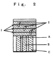
- Figure 2 shows a diagram describing preparation of lead-out
electrodes in Preparation Example 2.
-
-
The numbers and characters in Figures mean the following portions:
- 1:
- Silver paste
- 2:
- A window for a lead-out electrode
- A:
- Electrode A
- B:
- Electrode B
- C:
- Electrode C
THE MOST PREFERRED EMBODIMENT TO CARRY OUT THE
INVENTION
-
The hydrophobic particles used in the present invention are not
particularly limited as long as the surface of the particles exhibits the
hydrophobic property and various types of particles can be used. The
hydrophobic particles can be classified into hydrophobic organic particles
and hydrophobic inorganic particles. Examples of the hydrophobic
organic particles include particles of organic pigments, organic fluorescent
materials, organic luminescent materials, organic photosensitive materials
and organic polymers. There are no particular restrictions with respect to
the particles of these materials.
-
Examples of the hydrophobic inorganic particles include inorganic
particles such as particles of ITO (indium tin oxide), tin oxide and zinc
which are conductive particles and particles of zinc oxide, titanium oxide,
silica and alumina, which are treated on the surface to provide the
hydrophobic property.
-
The form and the size of the hydrophobic organic and inorganic
particles are not particularly limited. Powder having a diameter of 10 µm
or smaller is preferably used.
-
The surfactant of a ferrocene derivative used in the present
invention is a surfactant which comprises a ferrocene derivative as the
effective component. Various surfactants such as nonionic surfactants,
cationic surfactants and anionic surfactants are included. Examples of
the surfactant of a ferrocene derivative include ferrocene derivatives of the
ammonium type which are shown in Japanese Patent Application Laid-Open
No. Showa 63(1988)-243298; ferrocene derivatives of the ether type
and ferrocene derivatives of the ester type which are shown in
International Patent Application Laid-Open No. WO89/01939; ferrocene
derivatives of the pyridinium type which are shown in Japanese Patent
Application Laid-Open No. Heisei 1(1989)-226894; and various other
ferrocene derivatives which are shown in Japanese Patent Application
Laid-Open Nos. Heisei 2(1990)-83387, Heisei 2(1990)-83396, Heisei
2(1990)-96585, Heisei 2(1990)-188594, Heisei 2(1990)-235859, Heisei
2(1990)-250892, Heisei 2(1990)-250893, Heisei 2(1990)-256692, Heisei
2(1990)-256693, Heisei 4(1992)-26695 and Heisei 6(1994)-93497.
-
Among these surfactants of ferrocene derivatives, the following
compounds are preferably used:
wherein PEG represents polyethylene glycol (the average molecular
weight: 600).
-
The above surfactants of ferrocene derivatives may be used singly or
in combination of two or more.
-
The preferred embodiments of the present invention will be
described in the following.
-
In the present invention, as the first step, the hydrophobic particles
and conductive particles are dispersed in an aqueous medium containing
the surfactant of a ferrocene derivative as the dispersant. Examples of
the aqueous medium include water, mixtures of water and alcohols,
mixtures of water and acetone and other various aqueous dispersion media.
The equilibrium concentration of the dispersant is not particularly limited
as long as the hydrophobic particles can be dispersed. The equilibrium
concentration is generally 10 µg/ml or greater and preferably 30 µg/ml or
greater. The dispersant can be used in any great concentrations as long
as the dispersant can be dissolved in the aqueous medium and there is no
upper limit of the equilibrium concentration. The equilibrium
concentration is defines as follows. In general, when hydrophobic
particles are dispersed in a solution containing a dispersant, the
dispersant is adsorbed to the surface of the hydrophobic particles and the
concentration of the dispersant in the aqueous solution decreases due to
this adsorption. The adsorption reaches an equilibrium after a sufficient
period of time and the concentration of the dispersant in the aqueous
solution becomes constant. The concentration of the dispersant in the
aqueous solution in this condition is defined as the equilibrium
concentration.
-
The equilibrium concentration will be described in the following
with reference to the surfactant of a ferrocene derivative expressed by
formula (I) as the example.
-
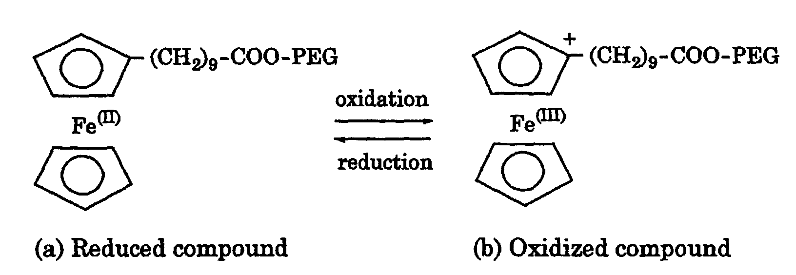
In an aqueous media, the dispersant (the agent for micelle
formation) which works for dispersing a pigment is in two forms: (a) a
neutral form and (b) a positively charged form. The two forms are
reversibly converted to each other by the oxidation reaction and the
reduction reaction. The compound of form (a) will be referred to as a
reduced compound and the compound of form (b) will be referred to as an
oxidized compound. The relation between the two compounds are shown
in the following:
-
The agent for micelle formation in form (a) is adsorbed to the surface
of a pigment and contributes to the dispersion. When a dispersion of a
pigment is prepared using the agent for micelle formation described above,
the agent in form (a) alone is present in the initial period of the
preparation of the dispersion. During the preparation of the dispersion or
after the dispersion has been prepared, a portion of the agent for micelle
formation is oxidized and the agent in form (b) is formed. The agent in
form (b) is not adsorbed to the pigment and remains floating in the
dispersion. A portion of the agent in form (a) is not adsorbed to the
pigment and remains floating in the dispersion. The agents not adsorbed
to the pigment and remaining floating in the dispersion are in equilibrium
with the agent adsorbed to the pigment. After a sufficient period of time,
i.e., when the dispersion is stabilized, the concentrations of the agents in
various forms are constant. The equilibrium concentration means the
total of the concentrations of the agent in form (a) and the agent in form (b)
both remaining floating in the dispersion.
-
The equilibrium concentration of the dispersant can be measured by
completely removing the hydrophobic particles by centrifugation and
measuring the concentration of the dispersant remaining in the aqueous
solution. The concentration of the surfactant of a ferrocene derivative as
the dispersant can be measured by the analysis of iron.
-
The concentration of the hydrophobic particles is not particularly
limited as long as the hydrophobic particles can be dispersed in the
aqueous medium. The concentration is generally 0.1 to 50.0% by weight
and preferably 0.5 to 30.0% by weight.
-
When the dispersion is prepared, a supporting salt (a supporting
electrolyte) may be used, where necessary. The supporting salt is used to
adjust the electric conductivity of the aqueous medium. The amount of
the supporting salt is not particularly limited as long as the supporting
salt does not adversely affect dispersing the hydrophobic particles. The
supporting salt is used generally in an amount of about 0 to 300 parts by
weight and preferably about 50 to 200 parts by weight per 1 part by weight
of the above dispersant. The electrolysis may be conducted without using
any supporting salt. When the electrolysis is conducted without using
any supporting salt, a high purity thin film containing no supporting salt
can be obtained. When the supporting salt is used, the supporting salt is
not particularly limited as long as the supporting salt does not adversely
affect formation of micelles or precipitation of the hydrophobic particles to
an electrode and allows adjustment of the electric conductivity of the
aqueous medium.
-
Preferable examples of the supporting salt include salts of sulfuric
acid such as lithium, potassium, sodium, rubidium and aluminum sulfates;
salts of acetic acid such as lithium, potassium, sodium, rubidium,
beryllium, magnesium, calcium, strontium, barium and aluminum
acetates; halogenated salts such as lithium, potassium, sodium, rubidium,
calcium, magnesium and aluminum halides; and salts of water-soluble
oxides such as lithium, potassium, sodium, rubidium, calcium, magnesium
and aluminum salts of water-soluble oxides, which are generally used as
the supporting salt. The supporting salt may be used singly or in
combination of two or more.
-
To control the concentrations of the oxidized compound and the
reduced compound, an ion exchange resin may be added to the dispersion
to adsorb and remove the oxidized compound of the cationic surfactant of a
ferrocene derivative or a reducing agent may be added to the dispersion to
reduce the oxidized compound. In the equilibrium concentration of the
surfactant of a ferrocene derivative, the concentration of the oxidized
compound is controlled to 40 µg/ml or smaller and preferably 20 µg/ml or
smaller and the concentration of the reduced compound is controlled to 50
to 300 µg/ml and preferably 100 to 200 µg/ml. An ion exchange resin and
a reducing agent may be used in combination. When the concentration of
the oxidized compound in the equilibrium concentration of the surfactant
of a ferrocene derivative is greater than the above range, a film of a color is
formed on an electrode which should not be coated with a film of this color
in the preparation of the color filter (color overlapping). When the
concentration of the reduced compound is smaller than the above range,
the diameter of the dispersed pigment increases and the optical property of
the obtained color filter becomes poor. When the concentration of the
reduced compound is greater than the above range, color filters are not
formed by electrolysis or films are not formed on end portions of the
electrode pattern due to a decreased speed of the film formation.
-
As the ion exchange resin, cation exchange resins and chelate resins
can be used. Ion exchange resins which selectively adsorb the oxidized
compound of the surfactant of a ferrocene derivative and hardly adsorb the
reduced compound are preferable. Specifically, methacrylic and acrylic
weakly acidic cation exchange resins are preferable as the cation ion
exchange resin and chelate resins of the iminodiacetic acid type are
preferable as the chelate resin. The ion exchange resins are used after
being converted into the lithium type. The resins of the lithium type
contribute to the long time stability of the dispersion, in particular, when
the dispersion is acidic because oxidation of ferrocene is suppressed due to
selective removal of hydrogen ion.
-
As the reducing agent, reducing agents soluble in water are
preferable. Examples of the reducing agent include salts of thiosulfuric
acid, sulfurous acid, phosphorous acid, oxalic acid and citric acid. When
the amount of the reduced compound of the surfactant of a ferrocene
derivative is increased excessively by reduction of the oxidized compound,
the excess amount of the surfactant of a ferrocene derivative can be
removed by addition of an adsorbent. Examples of the adsorbent include
silica, alumina, active carbon and crosslinked polymers such as crosslinked
styrene-divinylbenzene copolymers. Among these adsorbents, the
styrenic synthetic adsorbents having a non-polar crosslinked structure
having a specific surface area of 200 m2/g or larger are preferable since
these adsorbents can adsorb and remove the surfactant of a ferrocene
derivative in a small amount without affecting the stability of the
dispersion.
-
The dispersion of the hydrophobic particles prepared above is used
without further treatments when the concentration of the hydrophobic
particles is within a prescribed range. When the concentration is greater
than a prescribed range, the concentration can be adjusted to a value
within the prescribed range by diluting the dispersion with an aqueous
medium. Where necessary, an adsorbent is added to adsorb an excess
amount of the surfactant of a ferrocene derivative and the equilibrium
concentration of the surfactant of a ferrocene derivative is adjusted to a
value within a prescribed range. Then, the adsorbent and the
hydrophobic particles having large diameters in the above dispersion are
removed by a conventional method such as centrifugation and the object
dispersion can be produced.
-
In the dispersion prepared as described above, it is preferable that
the concentration of the hydrophobic particles is in the range of 0.2 to
10.0% by weight and more preferably 0.5 to 5.0% by weight. It is
preferable that the equilibrium concentration of the reduced compound of
the surfactant of a ferrocene derivative is in the range of 50 to 300 µg/ml
and more preferably in the range of 100 to 200 µg/ml.
-
In conventional processes in which the equilibrium concentration
cannot be adjusted after the dispersion has been prepared, the
concentration of the hydrophobic particles in the prepared dispersion must
be adjusted by controlling the concentration of the hydrophobic particles
when the components are first mixed together. This arises based on the
following phenomenon. When the hydrophobic particles are dispersed in
a great concentration, a dispersant is required in an excess amount. It
may be considered that, when the concentration of the hydrophobic
particles is adjusted to the prescribed value by diluting the obtained
dispersion, the equilibrium concentration of the dispersant may also be
decreased along with the concentration of the hydrophobic particles and
the prescribed concentrations can be achieved. However, in the actual
operation, the hydrophobic particles aggregate together during the
operation for producing the dispersion and the hydrophobic particles
cannot be dispersed unless the dispersant is added in an amount more
than the amount used above.
-
The equilibrium concentration of the dispersant can be measured in
accordance with the method of solubilization of a dye, the electrochemical
method and the plasma luminescence analysis described in the following.
(1) The method of solubilization of a dye
-
After a dispersion of hydrophobic particles is treated by
centrifugation, the supernatant solution is taken and the absorption
spectrum of the solution is obtained by a measurement. Then, a dye is
added to and dissolved in the solution. The excess amount of the dye is
removed and a portion of the supernatant solution is taken. The
absorption spectrum of this supernatant solution is obtained by a
measurement. A differential spectrum between the spectrum of the
solution obtained before addition of the dye and the spectrum of the
solution obtained after addition of the dye is obtained by calculation.
Separately, solutions are prepared by solubilizing the dye with various
known amounts of the dispersant which is used for dispersing the
hydrophobic particles and absorption spectra of these solutions are
obtained by measurements. A calibration curve showing the relation
between the concentration of the dispersant in the prepared solutions and
the absorption spectrum of the prepared solutions is obtained. The
equilibrium concentration of the dispersant is obtained from the
calibration curve and the differential spectrum obtained above.
-
The dye which can be used for the above method is not particularly
limited as long as the dye can be solubilized with the dispersant. For
example, azo dyes and phthalocyanine dyes can be used. The centrifugal
force in the treatment of centrifugation is not particularly limited as long
as the hydrophobic particles are precipitated and the dispersant in the
equilibrium concentration is not precipitated although the actual condition
depends on the specific gravity of the hydrophobic particles.
(2) The electrochemical method
-
In accordance with the same procedures as those described in (1), a
supernatant solution is taken after the centrifugation and the differential
pulse voltametry is conducted.
-
The equilibrium concentration is calculated from the result obtained
above and a calibration curve obtained in accordance with the differential
pulse voltametry using various known amounts of the dispersant.
-
In the differential pulse voltametry, the presence or the absence of
the peaks assigned to the oxidizing substance can be found. Therefore, it
can be found whether the amount of addition of the ion exchange resin is
suitable.
(3) The plasma luminescence analysis
-
In accordance with the same procedures as those described in (1) the
method of solubilization of a dye, a supernatant solution is taken after the
centrifugation and the plasma luminescence analysis is conducted. The
equilibrium concentration of the dispersant is calculated from the obtained
result and a calibration curve prepared in advance.
-
To form a thin film on a substrate by the electrolytic treatment
using the dispersion of the hydrophobic particles, a conductive substrate is
dipped into the above dispersion and the electrolysis is conducted by
passing an electric current through the substrate which is used as an
electrode. A thin film of the hydrophobic particles can thus be formed on
the conductive substrate. The condition of the electrolysis can be suitably
selected in accordance with the situation. The temperature of the
dispersion is generally 0 to 70°C and preferably 5 to 25°C and the voltage
is generally 0.3 to 1.5 V and preferably 0.4 to 1.0 V.
-
As the conductive substrate, metal substrates such as aluminum
substrate and insulating substrates such as glasses (glass containing no
alkalis, quartz glass and soda lime glass), plastics and ceramics on which a
conductive thin film such as films of ITO (indium tin oxide), tin dioxide,
platinum, graphite, chromium, nickel and antimony oxide are formed, are
used.
-
On the thin film of the hydrophobic particles thus formed on the
conductive substrate, a protective film of an agent forming a flat film may
be formed as the post treatment, where necessary, to protect the surface.
To form the protective film on the thin film, the substrate on which the
thin film is formed is set at a spin coater. After droplets of the agent for
forming a flat film are placed on the surface of the substrate using a
dispenser, the substrate is rotated at a high speed and coated with the
agent uniformly. The coated substrate is baked at a prescribed
temperature for a prescribed time to cure the coating film and a protective
film can be formed on the thin film.
-
A color filter is prepared by forming thin films of the three primary
colors of R, G and B (R: red, G: green and B: blue) on a transparent
substrate using dispersions of hydrophobic particles prepared as described
above. Particles of organic pigments are used as the hydrophobic
particles in the above dispersions.
-
In the preparation of the color filter, a transparent substrate having
patterned transparent electrodes is used. A glass substrate having ITO
electrodes formed with a pattern of stripes is preferable as the substrate.
-
As the organic pigments of R, G and B, pigments having excellent
light resistance, heat resistance and chemical resistance are preferable.
The pigment can be used singly or as a mixture of two or more.
-
Examples of the typical organic pigments in terms of the color index
number (C. I.) include red pigments such as Pigment Reds 9, 81, 97, 122,
123, 144, 146, 149, 166, 168, 169, 177, 180, 192, 209, 215, 216, 217, 220,
223, 224, 226, 227, 228, 240 and 254; yellow pigments such as Pigment
Yellows 1, 3, 12, 13, 14, 17, 20, 24, 34, 55, 74, 81, 83, 86, 93, 101, 109, 110,
113, 117, 125, 128, 129, 137, 138, 139, 147, 148, 150, 152, 153, 154, 166,
168, 173, 181, 185 and 199; orange pigments such as Pigment Oranges 13,
31,36, 38, 40, 42, 43, 51, 55, 59, 61, 64, 65 and 71; green pigments such as
Pigment Greens 7 and 36; blue pigments such as Pigment Blues 15:1, 15:2,
15:3, 15:4, 15:6, 16, 22, 60 and 64; and violet pigments such as Pigment
Violets 19, 23, 29, 30, 37, 40 and 50.
-
The organic pigments may contain conductive particles mixed with
and dispersed in the pigments.
-
As the conductive particles used in the present invention, particles
of ITO, conductive tin oxides such as SnO2 and SnO·Sb and conductive zinc
oxides such as zinc oxide doped with aluminum and zinc antimonate
(ZnO·Sb2O5) and composite particles such as SiO2, TiO2 and barium
sulfate coated with conductive tin oxides can be used. The conductive
particles are used after the surface of the particles is made hydrophobic by
the treatment with coupling agents or polymers. In combination with the
above conductive particles, ultra fine particles of SiO2, TiO2, ZnO and
Al2O3 which have been subjected to a hydrophobic treatment may also be
occasionally used to adjust the thickness of the film in the film formation.
The conductive particles may be used singly or in combination of two or
more.
-
To form thin films of the organic pigments of the three primary
colors constituting a color filter, a thin film of a desired color selected from
red, green and blue is first formed with a desired pattern using a
dispersion containing an organic pigment of the desired color in accordance
with the procedures for preparation of a thin film described above.
Subsequently, this procedure is conducted twice more using organic
pigments of different colors in place of the pigment of the above color.
Thus, a color filter having thin films of R, G and B can be obtained.
-
On the color filter having thin films of R, G and B obtained as
described above, a protective film is formed as the post treatment, where
necessary. The protective film is formed in accordance with the same
procedures as those described above and the formed protective film
protects the surface of the color filter having thin films of R, G and B.
-
A color filter can be prepared by forming an ITO film on the color
filter having thin films of R, G and B obtained above in accordance with a
conventional process.
-
The present invention will be described more specifically with
reference to examples in the following. However, the present invention is
not limited to the examples.
-
The equilibrium concentration of a surfactant of a ferrocene
derivative and the concentration of an oxidized compound in a dispersion
were determined by the measurements in accordance with the following
methods.
-
A micelle dispersion was subjected to a centrifugal treatment using
an ultracentrifuge at 50,000 revolutions per minute (referred to as rpm,
hereinafter) for 60 minutes. Hydrophobic particles were precipitated and
a supernatant solution was taken. When the hydrophobic particles were
left remaining in the supernatant solution, the above centrifugal
treatment was repeated and the hydrophobic particles were completely
removed (in general, the treatment was repeated 2 to 5 times).
-
The total concentration of the oxidized compound and the reduced
compound of the surfactant of a ferrocene derivative which are not
adsorbed to pigments was determined by the measurement of the
concentration of iron in the supernatant solution in accordance with the
plasma luminescence analysis and used as the equilibrium concentration.
-
The concentration of the oxidized compound of the surfactant of a
ferrocene derivative was determined by the measurement of the
absorbance of the supernatant solution at 627 nm. To calculate the
concentration, solutions of the oxidized compound of the surfactant of a
ferrocene derivative in known concentrations were prepared in advance by
adding cerium(IV) sulfate to the reduced compound of the surfactant of a
ferrocene derivative in an amount of 1.1 equivalent per 1 equivalent of the
surfactant to completely oxidize the ferrocene portion into ferrocenium ion
and the absorbance of the prepared solutions at 627 nm was measured.
The concentration of the oxidized compound was obtained from these
measurements. The limit of detection of the oxidized compound was 5
µg/ml. The concentration of the reduced compound was obtained by
subtracting the concentration of the oxidized compound from the
equilibrium concentration.
Preparation Example 1
(1) Preparation of a dispersion of a red organic pigment
-
To 1,000 parts by weight of pure water, 8.2 parts by weight of IDFE
expressed by formula (I) described above as the surfactant of a ferrocene
derivative, 50.0 parts by weight of a red pigment, C. I. Pigment Red 177, as
the hydrophobic particles and 1.05 parts by weight of lithium bromide
monohydrate were added and the components were mixed together. After
being dispersed by an ultrasonic homogenizer, the mixture was treated by
the centrifugal separation at 10,000 rpm and particles having large
diameters were removed. After the content of solid components and the
equilibrium concentration in the dispersion of the pigment which had been
dispersed and classified were measured, the dispersion was diluted with a
0.01 mole/liter aqueous solution of lithium bromide containing 150 µg/ml of
IDFE so that the concentration of solid components was adjusted to 2.0%
by weight and a dispersion of a red pigment containing C. I. Pigment Red
177 was prepared.
-
Separately, to 1,000 parts by weight of pure water, 9.45 parts by
weight of IDFE, 50.0 parts by weight of a yellow pigment, C. I. Pigment
Yellow 83, as the hydrophobic particles and 1.05 parts by weight of lithium
bromide monohydrate were added and the components were mixed
together. After being dispersed by an ultrasonic homogenizer, the
mixture was treated by the centrifugal separation at 10,000 rpm and
particles having large diameters were removed. After the content of solid
components and the equilibrium concentration in the dispersion of the
pigment which had been dispersed and classified were measured, the
dispersion was diluted with a 0.01 mole/liter aqueous solution of lithium
bromide containing 150 µg/ml of IDFE so that the concentration of solid
components was adjusted to 2.0% by weight and a dispersion of a yellow
pigment containing C. I. Pigment Yellow 83 was prepared.
-
A dispersion of a red organic pigment was prepared by mixing 75
parts by weight of the dispersion of a red pigment containing C. I. Pigment
Red 177 and 25 parts by weight of the dispersion of a yellow pigment
containing C. I. Pigment Yellow 83.
(2) Preparation of a dispersion of a green organic pigment
-
To 1,000 parts by weight of pure water, 8.0 parts by weight of IDFE,
50.0 parts by weight of a green pigment, C. I. Pigment Green 36, as the
hydrophobic particles and 1.05 parts by weight of lithium bromide
monohydrate were added and the components were mixed together. After
being dispersed by an ultrasonic homogenizer, the mixture was treated by
the centrifugal separation at 8,000 rpm and particles having large
diameters were removed. After the content of solid components and the
equilibrium concentration in the dispersion of the pigment which had been
dispersed and classified were measured, the dispersion was diluted with a
0.01 mole/liter aqueous solution of lithium bromide containing 150 µg/ml of
IDFE so that the concentration of solid components was adjusted to 2.0%
by weight and a dispersion of a green pigment containing C. I. Pigment
Green 36 was prepared.
-
A dispersion of a pigment containing C. I. Pigment Yellow 83 was
prepared in accordance with the same procedures as those conducted in
(1).
-
A dispersion of a green organic pigment was prepared by mixing
82.5 parts by weight of the dispersion of a green pigment containing C. I.
Pigment Green 36 and 17.5 parts by weight of the dispersion of a yellow
pigment containing C. I. Pigment Yellow 83.
(3) Preparation of a dispersion of a blue organic pigment
-
To 1,000 parts by weight of pure water, 10.8 parts by weight of IDFE,
50.0 parts by weight of a blue pigment, C. I. Pigment Blue 15:6, as the
hydrophobic particles and 1.05 parts by weight of lithium bromide
monohydrate were added and the components were mixed together. After
being dispersed by an ultrasonic homogenizer, the mixture was treated by
the centrifugal separation at 10,000 rpm and particles having large
diameters were removed. After the content of solid components and the
equilibrium concentration in the dispersion of the pigment which had been
dispersed and classified were measured, the dispersion was diluted with a
0.01 mole/liter aqueous solution of lithium bromide containing 150 µg/ml of
IDFE so that the concentration of solid components was adjusted to 2.0%
by weight and a dispersion of a blue organic pigment was prepared.
Preparation Example 2
[Preparation of a substrate having stripes of ITO electrodes and windows
for lead-out electrodes]
-
A glass substrate (320 × 300 × 0.7 mm; manufactured by
GEOMATIC Company) which was coated with an ITO film having a sheet
resistivity of 20 Ω/□ was subjected to a patterning treatment and stripes
of ITO electrodes having a width of 90 µm were formed at a distance of 20
µm between the electrodes. Thus, a substrate having the stripes of ITO
electrodes shown in Figure 1 was prepared.
-
The substrate prepared above was spin coated with an acrylic resist
(CT; manufactured by FUJI FILM OLIN Company) at 850 rpm and heated
in an oven at 100°C for 45 minutes. Then, while the position was
accurately adjusted using a light exposure machine (the proximity gap: 60
µm), the coated substrate was exposed to light through a mask for forming
lead-out electrodes (the energy of the exposed light of i-ray: 40 mJ/cm2).
After the exposed substrate was developed for 1 minute with a developer of
an aqueous solution of an inorganic alkali (a 0.1N aqueous solution of
sodium carbonate; manufactured by FUJI FILM OLIN Company; diluted
with CD pure water), the substrate was washed with pure water and
heated in an oven at 200°C for 60 minutes. After windows for lead-out
electrodes 2 shown in Figure 2 were prepared, silver paste 1 was placed
and lead-out electrodes were formed.
Example 1
(1) Preparation of a dispersion of conductive tin oxide
-
To 1,000 parts by weight of pure water, 16.6 parts by weight of IDFE,
200.0 parts by weight of conductive tin oxide (manufactured by
MITSUBISHI MATERIAL Co., Ltd.) which had been subjected to a
hydrophobic treatment with isobutyltrimethoxysilane and 1.05 parts by
weight of lithium bromide monohydrate were added and the components
were mixed together. After the mixture was dispersed by an ultrasonic
homogenizer, 50 parts by weight of a chelate resin of the iminodiacetic acid
type (DIAION CR-11; manufactured by MITSUBISHI KAGAKU Co., Ltd.)
which had been conditioned into the lithium type was added as the ion
exchange resin and the mixture was mixed for 24 hours. Then, particles
having large diameters were removed by the centrifugal separation at
3,000 rpm and the ion exchange resin was removed by filtration using a
filter having a pore diameter of 1 µm. After the content of solid
components in the obtained dispersion was measured, the dispersion was
diluted with a 0.01 mole/liter aqueous solution of lithium bromide
containing 100 µg/ml of IDFE so that the concentration of solid
components was adjusted to 8.0% by weight and a dispersion of conductive
tin oxide was prepared.
(2) Preparation of a red micelle dispersion containing conductive tin
oxide
-
A red micelle dispersion was prepared by mixing 62.5 parts by
weight of the dispersion of a red organic pigment prepared in Preparation
Example 1 and 37.5 parts by weight of the dispersion of conductive tin
oxide prepared above. The equilibrium concentration of the surfactant
and the concentrations of the oxidized compound and the reduced
compound in the red micelle dispersion are shown in Table 1.
(3) Preparation of a green micelle dispersion containing conductive tin
oxide
-
A green micelle dispersion was prepared by mixing 62.5 parts by
weight of the dispersion of a green organic pigment prepared in
Preparation Example 1 and 37.5 parts by weight of the dispersion of
conductive tin oxide prepared above. The equilibrium concentration of
the surfactant and the concentrations of the oxidized compound and the
reduced compound in the green micelle dispersion are shown in Table 1.
(4) Preparation of a blue micelle dispersion containing conductive tin
oxide
-
A blue micelle dispersion was prepared by mixing 62.5 parts by
weight of the dispersion of a blue organic pigment prepared in Preparation
Example 1 and 37.5 parts by weight of the dispersion of conductive tin
oxide prepared above. The equilibrium concentration of the surfactant
and the concentrations of the oxidized compound and the reduced
compound in the blue micelle dispersion are shown in Table 1.
(5) Preparation of a color filter
-
The ITO substrate prepared in Preparation Example 2 was dipped
into the red micelle dispersion prepared above and an electrode was
connected to the R-rows in the stripes of the ITO electrodes. Electrolysis
was conducted for 10 minutes using the ITO electrodes as the anodes and a
stainless steel plate as the cathode at a constant electric potential of 0.5 V
(based on the Ag/AgCl electrodes) and red thin films were formed. The
substrate on which the red thin films were formed was washed with pure
water and baked at 120°C for 30 minutes as the post treatment. The
substrate was then dipped into the green micelle dispersion prepared
above and an electrode was connected to the G-rows of the stripes of the
ITO electrodes. The electrolysis was conducted for 15 minutes at a
constant electric potential of 0.5 V in the same manner as that described
above and green thin films were formed. The post treatment was
conducted in the same manner as that on the red thin films. Finally, the
substrate was dipped into the blue micelle dispersion prepared above and
an electrode was connected to the B-rows of the stripes of the ITO
electrodes. The electrolysis was conducted for 10 minutes at a constant
electric potential of 0.5 V in the same manner as that described above and
blue thin films were formed. The post treatment was conducted in the
same manner as that on the red thin film and a color filter having thin
films of R, G and B was prepared. In the obtained color filter, films of the
pigments were formed uniformly on the entire desired potions including
end portions of the stripes. Mixing of the colors in the color filter was
examined by measuring the decrease in the absorbance at 610 nm after
forming and baking the films of the three colors from the corresponding
absorbance immediately after forming and baking the first red films and
the decrease in the absorbance at 545 nm after forming and baking the
films of the three colors from the corresponding absorbance immediately
after forming and baking the second green films. The results are shown
in Table 1. As shown in Table 1, the decreases in the absorbances were
very small and almost no color overlapping was found.
Comparative Example 1
-
To 1,000 parts by weight of pure water, 17.2 parts by weight of IDFE,
200.0 parts by weight of conductive tin oxide (manufactured by
MITSUBISHI MATERIAL Co., Ltd.) which had been subjected to a
hydrophobic treatment with isobutyltrimethoxysilane and 1.05 parts by
weight of lithium bromide monohydrate were added and the components
were mixed together. After the mixture was dispersed by an ultrasonic
homogenizer, 50 parts by weight of a chelate resin of the iminodiacetic acid
type (DIAION CR-11; manufactured by MITSUBISHI KAGAKU Co., Ltd.)
which had been conditioned into the lithium type was added as the ion
exchange resin and the mixture was mixed for 24 hours. Then, particles
having large diameters were removed by the centrifugal separation at
3,000 rpm and the ion exchange resin was removed by filtration using a
filter having a pore diameter of 1 µm. After the content of solid
components in the obtained dispersion was measured, the dispersion was
diluted with a 0.01 mole/liter aqueous solution of lithium bromide
containing 500 µg/ml of IDFE so that the concentration of solid
components was adjusted to 8.0% by weight and a dispersion of conductive
tin oxide was prepared.
(2) Preparation of a red micelle dispersion containing conductive tin
oxide
-
A red micelle dispersion was prepared by mixing 62.5 parts by
weight of the dispersion of a red organic pigment prepared in Preparation
Example 1 and 37.5 parts by weight of the dispersion of conductive tin
oxide prepared above. The equilibrium concentration of the surfactant
and the concentrations of the oxidized compound and the reduced
compound in the red micelle dispersion are shown in Table 1.
(3) Preparation of a green micelle dispersion containing conductive tin
oxide
-
A green micelle dispersion was prepared by mixing 62.5 parts by
weight of the dispersion of a green organic pigment prepared in
Preparation Example 1 and 37.5 parts by weight of the dispersion of
conductive tin oxide prepared above. The equilibrium concentration of
the surfactant and the concentrations of the oxidized compound and the
reduced compound in the green micelle dispersion are shown in Table 1.
(4) Preparation of a blue micelle dispersion containing conductive tin
oxide
-
A blue micelle dispersion was prepared by mixing 62.5 parts by
weight of the dispersion of a blue organic pigment prepared in Preparation
Example 1 and 37.5 parts by weight of the dispersion of conductive tin
oxide prepared above. The equilibrium concentration of the surfactant
and the concentrations of the oxidized compound and the reduced
compound in the blue micelle dispersion are shown in Table 1.
(5) Preparation of a color filter
-
A color filter having thin films of R, G and B was prepared using the
micelle dispersions of various colors prepared above in accordance with the
same procedures as those conducted in Example 1. The obtained color
filter had pigment films much thinner than those of the color filter
prepared in Example 1. No film was formed at end portions of the stripes.
The decreases in the absorbances were obtained in accordance with the
same procedures as those conducted in Example 1 and the results are
shown in Table 1.
Comparative Example 2
-
A color filter having thin films of R, G and B was prepared in
accordance with the same procedures as those conducted in Example 1
except that the removal of the oxidized compound with the ion exchange
resin was not conducted in (1) Preparation of a dispersion of conductive tin
oxide. The decreases in the absorbances of the obtained color filter were
obtained in accordance with the same procedures as those conducted in
Example 1 and the results are shown in Table 1. As shown in Table 1, the
decreases in the absorbances were great and the color overlapping took
place.
Comparative Example 3
(1) Preparation of a dispersion of ITO particles
-
To 1,000 parts by weight of pure water, 4.0 parts by weight of FPEG
expressed by formula (II) shown above as the surfactant of a ferrocene
derivative, 50.0 parts by weight of ITO particles (indium tin oxide;
manufactured by MITSUBISHI MATERIAL Co., Ltd.) which had been
subjected to a hydrophobic treatment with isobutyltrimethoxysilane and
1.05 parts by weight of lithium bromide monohydrate were added and the
components were mixed together. After the mixture was dispersed by an
ultrasonic homogenizer, particles having large diameters were removed by
the centrifugal treatment at 1,500 rpm. After the content of solid
components in the obtained dispersion was measured, the dispersion was
diluted with a 0.01 mole/liter aqueous solution of lithium bromide so that
the concentration of solid components was adjusted to 4.0% by weight and
a dispersion of ITO particles was prepared.
(2) Preparation of a red micelle dispersion containing ITO particles
-
A red micelle dispersion was prepared by mixing 50 parts by weight
of the dispersion of a red organic pigment prepared in Preparation
Example 1, 50 parts by weight of the dispersion of ITO particles prepared
above and 1 part by weight of lithium bromide monohydrate. The
equilibrium concentration of the surfactant and the concentrations of the
oxidized compound and the reduced compound in the red micelle
dispersion are shown in Table 1.
(3) Preparation of a green micelle dispersion containing ITO particles
-
A green micelle dispersion was prepared by mixing 50 parts by
weight of the dispersion of a green organic pigment prepared in
Preparation Example 1 and 50 parts by weight of the dispersion of ITO
particles prepared above. The equilibrium concentration of the surfactant
and the concentrations of the oxidized compound and the reduced
compound in the green micelle dispersion are shown in Table 1.
(4) Preparation of a blue micelle dispersion containing ITO particles
-
A blue micelle dispersion was prepared by mixing 50 parts by
weight of the dispersion of a blue organic pigment prepared in Preparation
Example 1 and 50 parts by weight of the dispersion of ITO particles
prepared above. The equilibrium concentration of the surfactant and the
concentrations of the oxidized compound and the reduced compound in the
blue micelle dispersion are shown in Table 1.
(5) Preparation of a color filter
-
The ITO substrate prepared in Preparation Example 2 was clipped
into the red micelle dispersion prepared above and an electrode was
connected to the R-rows of the stripes of the ITO electrodes. Electrolysis
was conducted for 20 minutes using the ITO electrodes as the anodes and a
stainless steel plate as the cathode at a constant electric potential of 0.5 V
(based on the Ag/AgCl electrodes) and red thin films were formed. The
substrate on which the red thin films were formed was washed with pure
water and baked .at 120°C for 30 minutes as the post treatment. The
substrate was then dipped into the green micelle dispersion obtained above
and an electrode was connected to the G-rows of the stripes of the ITO
electrodes. The electrolysis was conducted for 15 minutes at a constant
electric potential of 0.5 V in the same manner as that described above and
green thin films were formed. The post treatment was conducted in the
same manner as that on the red thin film. Finally, the substrate was
dipped into the blue micelle dispersion obtained above and an electrode
was connected to the B-rows of the stripes of the ITO electrodes. The
electrolysis was conducted for 15 minutes at a constant electric potential of
0.5 V in the same manner as that described above and blue thin films were
formed. The post treatment was conducted in the same manner as that
on the red thin film and a color filter having thin films of R, G and B was
prepared. The decreases in the absorbances were obtained in accordance
with the same procedures as those conducted in Example 1. The results
are shown in Table 1. As shown in Table 1, the decreases in the
absorbances were great and the color overlapping took place.
Example 2
-
To 1,000 parts by weight of the dispersion of ITO particles prepared
in Comparative Example 3 (1), 2.63 parts by weight of disodium
hydrogencitrate 1.5 hydrate and 10 parts by weight of a synthetic
adsorbent (SEPABEADS SP-207; manufactured by MITSUBISHI
KAGAKU Co., Ltd.) were added and the mixture was stirred for 24 hours.
Then, the adsorbent was removed by filtration with a filter having a pore
diameter of 1 µm. A color filter having thin films of R, G and B was
prepared in accordance with the same procedures as those conducted in
Comparative Example 3 except that the dispersion of ITO particles
prepared above was used. The decreases in the absorbances were
obtained in accordance with the same procedures as those conducted in
Example 1. The results are shown in Table 1. As shown in Table 1, the
decreases in the absorbance were very small and almost no color
overlapping was found.
| | Color of micelle dispersion | Equilibrium concentration (µg/ml) | Concentration of oxidized compound (µg/ml) | Concentration of reduced compound (µg/ml) | Mixing of colors (decrease in absorbance) |
| | | | | | red to 3 colors | green to 3 colors, |
| Example 1 | red | 145 | 12 | 133 | 2% | 2% |
| green | 160 | 10 | 150 |
| blue | 148 | 18 | 130 |
| Example 2 | red | 185 | 35 | 150 | 2% | 2% |
| green | 110 | 28 | 82 |
| blue | 145 | 32 | 113 |
| Comparative Example 1 | red | 520 | 10 | 510 | 2% | 1% |
| green | 480 | 8 | 472 |
| blue | 515 | 15 | 500 |
| Comparative Example 2 | red | 206 | 146 | 60 | 20% | 15% |
| green | 195 | 120 | 75 |
| blue | 227 | 132 | 95 |
| Comparative Example 3 | red | 2100 | 210 | 1890 | 23% | 16% |
| green | 1950 | 180 | 1770 |
| blue | 2050 | 195 | 1855 |
INDUSTRIAL APPLICABILITY
-
As described above in detail, when a color filter is prepared using
the micelle dispersion of the present invention, pigment films are formed
uniformly on the surface for forming thin films of R, G and B, color
overlapping does not take place and the color filter can be prepared with
an excellent yield.