EP1091698B1 - Intramedullary nail insertion instruments - Google Patents
Intramedullary nail insertion instruments Download PDFInfo
- Publication number
- EP1091698B1 EP1091698B1 EP99932134A EP99932134A EP1091698B1 EP 1091698 B1 EP1091698 B1 EP 1091698B1 EP 99932134 A EP99932134 A EP 99932134A EP 99932134 A EP99932134 A EP 99932134A EP 1091698 B1 EP1091698 B1 EP 1091698B1
- Authority
- EP
- European Patent Office
- Prior art keywords
- sleeve
- housing
- assembly
- reamer
- reaming
- Prior art date
- Legal status (The legal status is an assumption and is not a legal conclusion. Google has not performed a legal analysis and makes no representation as to the accuracy of the status listed.)
- Expired - Lifetime
Links
Images








Classifications
-
- A—HUMAN NECESSITIES
- A61—MEDICAL OR VETERINARY SCIENCE; HYGIENE
- A61B—DIAGNOSIS; SURGERY; IDENTIFICATION
- A61B17/00—Surgical instruments, devices or methods
- A61B17/16—Instruments for performing osteoclasis; Drills or chisels for bones; Trepans
- A61B17/17—Guides or aligning means for drills, mills, pins or wires
- A61B17/1717—Guides or aligning means for drills, mills, pins or wires for applying intramedullary nails or pins
-
- A—HUMAN NECESSITIES
- A61—MEDICAL OR VETERINARY SCIENCE; HYGIENE
- A61B—DIAGNOSIS; SURGERY; IDENTIFICATION
- A61B17/00—Surgical instruments, devices or methods
- A61B17/56—Surgical instruments or methods for treatment of bones or joints; Devices specially adapted therefor
- A61B17/58—Surgical instruments or methods for treatment of bones or joints; Devices specially adapted therefor for osteosynthesis, e.g. bone plates, screws or setting implements
- A61B17/88—Osteosynthesis instruments; Methods or means for implanting or extracting internal or external fixation devices
- A61B17/8897—Guide wires or guide pins
Definitions
- the present invention relates to a surgical tool and method for accessing the intramedullary canal of a bone and more particularly to a minimally invasive reaming assembly and method for creating an entry portal into the canal of a bone and providing a working channel for reaming the canal of the bone to receive an intramedullary fracture reduction device.
- Bone fractures are repaired by inserting bone fracture reduction rods or intramedullary nails into the intramedullary canal of a bone in order to stay the fracture.
- it is conventional to make an Incision near the tip of the greater trochanter extending proximally in line with the fibres of the gluteus in order to create an entry portal through the bone and into the canal.
- it has been found to be difficult to correctly position the entry portal to the intramedullary canal from the greater trochanter and to ream the canal to the desired size without damaging the surrounding soft tissue, displacing the previously reduced fracture, or making extremely large incisions. This is especially true if the patient is obese of if flexion or abduction of the proximal fragment caused a portion of the greater trochanter to lie against the ilium.
- the canal is progressively reamed to a larger diameter from a smaller diameter in increments of about 0.5mm, from generally about 8mm, up to generally about 12.5mm.
- the surgeon starts with a small reamer, reams the bone, removes the reamer and then inserts a second reamer, 0.5mm larger in diameter than the previous reamer. The surgeon repeats this process until he has reached the required canal diameter for the intramedullary nail that has been selected for the patient.
- this type of surgery can be particularly bloody which presents other problems. Excess blood can obstruct the surgeon's view of the site being reamed and excessive blood flowing from the surgical site can create problems for the surgical staff particularly if the patient has a blood or bone disease. Thus, it is important that the surgical instrumentation provide for suctioning of the blood created by the surgery from the surgical site.
- a second problem has to do with the actual entry of the reamer into the intramedullary canal of the bone after it has passed through the soft tissues. Since the guide rod is so much smaller than the reamer (3mm compared to at least 8mm), the guide rod frequently will not stay centred in the opening created by the previous reamer, which results in the next reamer getting caught on the edge of the opening created by the previous reamer. Since the next reamer is larger in size, it will not fit smoothly into the opening created by the previous smaller reamer. This situation prevents the surgeon from being able to determine if the next larger reamer is correctly centred before he or she starts reaming the canal. In order for the surgeon to locate the opening with the present instrumentation, he typically has to make a larger incision in order to locate the entry portal and determine the correct centring of the reamers.
- U.S. Patent 5,624,447 which describes a surgical tool guide and entry portal positioned that provides a cannulated sleeve with a handle and a C-shiped soft tissue protector secured to the sleeve.
- U.S. Patent 5,569,262 describes a guide tool for surgical devices that is used for directing a surgical device into attachment with a bone segment and is used to protect a surgeon's fingers from the surgical device and from the jagged surface of the bone segment.
- U.S. Patent 5,443,469 describes a tubular tissue protection guard that is inserted into an incision or wound in order to accommodate reaming devices.
- the present invention consists of a reaming assembly 10 for creating an entry portal into the canal of a bone and providing a working channel in which to ream the canal of a bone, the assembly comprising:
- the reaming assembly allows for the passage of reamers of graduated sizes for progressively reaming the canal of a bone through the sleeve.
- the reaming assembly is used in combination with an entry portal tool for use in correctly placing the entry portal in the bone.
- An embodiment of the present invention is a minimally invasive reaming assembly 10 that includes as reaming sleeve 12, a housing 14 and an inner reamer 16 that fits within the cannulation of reaming sleeve 12.
- the rearning assembly 10 is used in combination with an entry portal tool 20 to locate the preferred placement of an entry portal and then to create an entry portal to the canal C of a bone B ( Figs. 1 and 2 ). Once the entry portal has been created and the reaming sleeve 12 is positioned in the bone B, the inner reamer 16 is removed from the housing 14 and reaming sleeve 12.
- the reaming sleeve 12 is then used as a working channel in which to progressively ream the canal of the bone B without losing the entry portal or irritating the soft tissue surrounding the entry portal.
- the entry portal tool 20 and the reaming assembly 10 are formed of stainless steel.
- Entry portal tool 20 is an elongated, cylindrically-shaped hollow sheath 22 having a proximal end 24, a bevelled distal end 26 and an upper and lower portion 28, 30 ( Fig. 2 ).
- the upper portion 28 includes at least one generally circular opening 32 in the sheath 22, and in a preferred embodiment has three openings. In one embodiment the openings 32 of the sheath 22 can be threaded.
- the entry portal tool 20 also includes a handle 34 that can be used by the surgeon to manipulale the entry portal tool 20.
- the handle 34 is elongated in shape and has proximal and distal ends 36, 38.
- the distal end 38 is removably connected to a selected circular opening 32 in the sheath 22.
- the handle 34 includes a through bore 40, a connecting mechanism 42 for connecting and disconnecting the handle 34 to the sheath 22 ( Fig. 5 ).
- the proximal end 36 is sized and shaped to accept a suction device S known to one skilled in the art that can be attached
- the connecting mechanism 42 is a spring-loaded plunger mechanism that utilises a series of retractable ball bearings 44 to connect and disconnect the handle 34 from a selected generally circular opening 32 in the sheath 22.
- a handle 34A has a connecting mechanism 42A that is a threaded portion 35 at the distal end 38 of the handle 34A.
- the threaded portion 35 of the handle distal end 38 engages threading in the circular openings 32 of the sheath 22.
- the handle 34A includes a generally cylindrical distal portion 37, a flat middle portion 39 and a generally cylindrical proximal end 41 that is configured to accept a suction device for suctioning fluids from the remaining site.
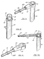
- FIG. 7A-C A third embodiment of the entry portal tool 20B is shown in Figs. 7A-C in which the proximal end 24 of the sheath 22 includes an annular lip 43 placed below circular opening 32.
- Handle 348 includes an elongated tubular member 45 having a proximal end 47, a distal end 49 and an annular collar 51 that serves as a gripper.
- Handle 348 also includes a connection portion 53 having a generally cylindrical ring 55 integral with an elongated housing 57 Housing 57 has a through bore 59 sized and shaped to accommodate the distal end 49 of the tubular member 45.
- Ring 55 includes at least one generally circular opening 61 that is aligned with bore 59 and is similar in size and shape to the circular opening 32 of the handle 348.
- Housing 57 includes a spring mechanism (not shown) connected to the tubular member 45, that allows the distal end 49 of the tubular member 45 to be retracted from the interior of the ring 55 so that ring 55 can be placed upon the proximal end 24 of sheath 22.
- the annular lip 43 provides a stop for connector portion 53.
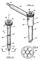
- Entry portal tools 20, 20A and B also include a cannulated obturator or elongated cylindrically-shaped tube 50 having a proximal and distal end 52, 54 and a central longitudinal axis LA ( Fig. 3 ).
- the distal end 54 has a conical top 56 that includes a plurality of openings 58.
- the plurality of openings 58 have a circular centre opening surrounded by five openings all of the same size, as shown in Fig. 4
- the proximal end 52 includes an annular collar 60 having a diameter greater than tube 50 and sheath 22.
- Tube 50 includes a cylindrical hub 62 at its proximal end 52 with a hub 62 Including openings 64 identical in configuration to the openings 58 of the conical tip 56.
- Tube 50 also can include a number of cylindrical hubs 66, each having openings 64, placed longitudinally in tube 50 between the proximal and distal end 52, 54 of tube 50 ( Fig. 3 ).
- the openings 64 of the hubs 62, 66 and the openings 58 of the conical tip 56 are aligned along parallel lines that are parallel with the central longitudinal axis LA of tube 50.
- Obturator 50 is sized and shaped for removably inserting into the hollow sheath 22 with the hollow sheath 22 being sized and shaped for removable insertion of the reaming sleeve 14 into the sheath 22 ( Fig. 2 ).
- the entry portal tools 20, 20A-B are configured to allow for the suctioning of blood out of the intramedullary canal into the reaming sleeve 12 and out the sheath 22, and through handle 34, 34A and B into a collection device.
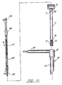
- the minimally invasive reaming assembly 10 includes reaming sleeve 12, housing 14 and inner reamer 16 ( Fig. 10 ).
- Reaming sleeve 12 as shown in Figs. 11-14 , is an elongated cylindrically-shaped hollow sleeve having a proximal and distal end 68, 70.
- Distal end 70 includes a plurality of cutting blades 72 of the kind generally known by one skilled in the art of orthopaedic surgery for cutting into the canal of a bone.
- the cutting blades 72 extend approximate 35mm up from the distal end 70 of the sleeve 12 on the outer surface 74 of sleeve 12.
- the outer surface 74 of proximal end 68 of sleeve 12 includes threading 76 on approximately 6mm in length of the proximal end 68. Positioned at the end of threading 76 is a ring of angled, horizontally extending teeth 78, in which the threading 76 and teeth 78 provide for engagement of the proximal end 68 of the sleeve 12 to the housing 14.
- Reaming sleeve 12 and housing 14 can be constructed as an integral unit, or sleeve 12 can be constructed without the housing 14 in which case the release mechanism for the inner reamer 16 would be part of the proximal end 68 of sleeve 12.
- the sleeve 12 and housing 14 are constructed of two separate pieces or elements that are connected together so that the reaming sleeve 12 can be replaced if necessary.
- housing 14 is preferably generally cylindrical in shape and includes a top portion 80, a bottom portion 82 and a centrally located, cylindrical through bore 84.
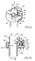
- Bore 84 indudes threading 85 on a portion of the bore's 84 surface ( Figs. 16-18 ).
- the threading 85 on bore 84 is configured to mate with the threading 76 on the proximal end 68 of sleeve 12.
- Top portion 80 includes a first side 86 and a second side 88 separated by a raised centre portion 90.
- First side 86 is approximately 6mm lower than centre portion 90 ( Fig. 15 ).
- First side 86 intersects part of centre portion 90 exposing a section of bore 84 creating opening 92 ( Figs.
- Opening 92 is adjacent a notch 94 on the surface of the first side 86 of housing 14.
- Notch 94 is sized and shaped to engage a tab 160 on the inner reamer 16.
- First side 86 also includes a through bore 95 adjacent to notch 94 ( Figs. 15 and 17 ).
- the part of the bottom portion 82 that is in alignment with first side 86 includes a generally oval-shaped cutout
- locking button 98 has an outer side 100, at inner side 102, and side walls 104.
- the inner side 102 of button 98 includes an upwardly extending cylindrical shaft 106 having a threaded opening 108.
- a notch 110 is placed on a portion of the outer side 100 of button 98, with notch 110 being sized and shaped to catch one of the teeth 78 on sleeve 12 ( Figs. 19-21 ).
- locking button 98 is a spring-loaded button that is to the housing by placing a spiral compression spring 112 over shaft 106 and inserting shaft 106 and spring 112 into bore 95.
- a threaded screw 114 is inserted into bore 95 from the first side 86 of housing 14 and engages the threaded opening 108 in shaft 106 ( Fig. 15 ).
- a spring-loaded locking button 98 is provided that can be depressed in order to allow the proximal end 68 of sleeve 12 to be screwed into threaded portion 85 of bore 84 and then released, causing the notch 110 on button 98 to engage one of the teeth 78 on sleeve 12, locking sleeve 12 into the housing 14.
- a portion of the second side 88 or housing 14 includes a centrally located, generally semicircular cutout 116.
- Wall 118 of centre portion 90 includes a pair of parallel, horizontally placed through bores 120 positioned on either side of bore 84 that are sized and shaped to accommodate the legs 126 of a release button 122.
- Release button 122 is provided in order to lock the reamer 16 or release the reamer 16 from housing 14 ( Figs. 24-26 ).
- release button 122 is generally U-shaped in which base 124 of the U-shape is crescent-shaped and legs 126 of the U-shape are generally cylindrical.
- release button 122 is a spring-loaded button that is constructed by placing spiral compression springs 132 over legs 126 and inserting legs 126 and springs 132 through bores 120 in the centre portion 90. The extending distal ends 130 of legs 126 are then inserted into corresponding openings 134 of a rectangular block 136, that includes a pair of vertical bores 138, that intersect the block openings 134. Pins (not shown) are inserted through vertical bores 138 and into openings 128 of legs 126 of the button 122, fastening the block 136 to the release button 122 ( Fig. 15 ).
- the rectangular block 136 includes a bevelled centre section 137 that allows the inner reamer 16 to be locked in place without releasing button 122.
- the inner reamer 16 of the reaming assembly 10 has an elongated cannulated body 144 and proximal and distal ends 146, 148 ( Figs. 10 and 22 ).
- elongated body 144 can also be formed from a solid rod that is not cannulated.
- Distal end 148 has a rotatable reaming head 150 of a type known to one skilled in the art of orthopaedic surgery ( Fig. 22 ).
- the rotatable reaming head 150 includes a plurality of cutting blades 152 suitable for cutting through the intramedullary canal of a bone.
- the proximal end 146 of inner reamer 16 includes a connection mechanism 154 configured in the shape of a drive shaft 156 of a type known to one skilled in the art of orthopaedic surgery ( Fig. 23 ). Any suitable connection mechanism 154 can be employed to interconnect or detachably connect the drive shaft 156 to a rotational driver, such as that found in a conventional reaming drill or other suitable device.
- inner reamer 16 can include a flexible centre section 147 that allows the reamer 16 to also be used to ream the proximal tibia, thus eliminating the need for a separate instrument.
- the flexible centre section 147 of inner reamer 16 can be formed by cutting concentric helical cuts in opposite directions in a metal tube so that torque can be applied.
- the concentric helical cuts will provide both rigidity and flexibility to the centre section 147 of the inner reamer 16.
- a portion of inner reamer 16 includes an annular collar 158 that is of a slightly larger diameter than the diameter of cannulated body 144 of inner reamer 16 ( Figs. 22 and 23 ).
- Collar 158 includes a tab 160 that is sized and shaped to mate with notch 94 housing 14 in order to secure inner reamer 16 in the housing 14.
- inner reamer 16 in the hosing 14 with the release button 122 in an open position which exposes notch 94 of housing 14.
- the button 122 is released, thus locking tab 160 in notch 94.
- the bevelled centre portion 137 of the block 136 allows tab 160 to slide into the notch 94 without having to expose notch 94.
- a plurality of reamers (not shown) of graduated sizes are used with the reaming apparatus 10 for progressively reaming the canal of a bone after the initial roaming has been performed with the inner reamer 16.
- the reamers are typically graduated in 0.5mm increments, however, other graduated dimensions are contemplated.
- the reaming assembly 10 and the entry portal tool 20 are used in combination to ream in a minimally invasive manner an intramedullary canal ( Figs. 1 and 8 ).
- a surgeon first uses the entry portal tool 20 to locate the most desirable location for the entry portal in the proximal femur or other long or flat bones.
- the multiple openings 58 and 64 of the conical tip and hubs 62, 66 of the entry portal tool 20 to enable precise placement of the guide pin. This is especially important in repairing fractures of the femoral neck where very precise placement of the entry portal is required.
- the surgeon makes an appropriate nominally invasive incision in the patient and using the entry portal tool handle 34, he or she inserts the entry portal sheath 22, with the obturator 50 inserted in the heath 22, into the incision.
- the surgeon places one or more guide pins (not shown) through a selected one of the plurality of openings 58, 64 in the obturator 50, and using fluoroscopy, evaluates the position of the guide pins. If the surgeon desires to change the position of the guide pins, he or she can place one or more of the pins into another opening, or can rotate the obturator 50 within the sheath 22 of the entry portal tool 20.
- the surgeon Once the surgeon has selected the best position for the entry portal, he will insert the guide pin into the bone. With the pin firmly imbedded in the bone, the obturator 50 is removed from the sheath 22 of the entry portal tool 20.
- the surgeon next inserts the reaming sleeve assembly 10 into sheath 22 and over the guide pin that is firmly imbedded in the bone ( Fig. 8 ).
- the pin will act as a guide as the reamer assembly 10 reams an entry portal into the canal of the bone ( Fig. 9 ).
- the surgeon removed the inner reamer 16 from the assembly 10 by depressing the release button 122 on the housing 14.
- the one or more guide pins are also removed with the inner reamer 16, however, the reaming sleeve 12 remains in place in the canal of the bone.
- the reaming sleeve 12 becomes a working channel through which the intramedullary canal can be opened up to the appropriate diameter using progressively larger sized reamers as described above.
- a suction device attached to handle 34, 34A-B of the entry portal tool 20, 20A-8 allows for the blood produced from the reaming to be suctioned up through holes 71 in the sleeve 12, into the sheath 22 of the entry portal tool 20, 20A-B and out its handle 34, 34A-B in to a collection container.
- entry portal tool 20 and the reaming sleeve 12 are removed and an intramedullary nail (pin or rod) is inserted into the canal.
- an entry portal into the canal of a bone can be created by a surgeon, who then uses the same assembly to provide a working channel in which to progressively ream the canal of the bone without damaging the soft tissues or losing the entry portal into the bone.
Landscapes
- Health & Medical Sciences (AREA)
- Surgery (AREA)
- Life Sciences & Earth Sciences (AREA)
- Biomedical Technology (AREA)
- Medical Informatics (AREA)
- Orthopedic Medicine & Surgery (AREA)
- Oral & Maxillofacial Surgery (AREA)
- Engineering & Computer Science (AREA)
- Dentistry (AREA)
- Heart & Thoracic Surgery (AREA)
- Nuclear Medicine, Radiotherapy & Molecular Imaging (AREA)
- Molecular Biology (AREA)
- Animal Behavior & Ethology (AREA)
- General Health & Medical Sciences (AREA)
- Public Health (AREA)
- Veterinary Medicine (AREA)
- Surgical Instruments (AREA)
- Joining Of Building Structures In Genera (AREA)
- Portable Nailing Machines And Staplers (AREA)
Abstract
Description
- The present invention relates to a surgical tool and method for accessing the intramedullary canal of a bone and more particularly to a minimally invasive reaming assembly and method for creating an entry portal into the canal of a bone and providing a working channel for reaming the canal of the bone to receive an intramedullary fracture reduction device.
- Bone fractures are repaired by inserting bone fracture reduction rods or intramedullary nails into the intramedullary canal of a bone in order to stay the fracture. In performing this type of surgery for femoral fractures for example, it is conventional to make an Incision near the tip of the greater trochanter extending proximally in line with the fibres of the gluteus in order to create an entry portal through the bone and into the canal. However, it has been found to be difficult to correctly position the entry portal to the intramedullary canal from the greater trochanter and to ream the canal to the desired size without damaging the surrounding soft tissue, displacing the previously reduced fracture, or making extremely large incisions. This is especially true if the patient is obese of if flexion or abduction of the proximal fragment caused a portion of the greater trochanter to lie against the ilium.
- In this type of surgery, after the entry portal has been established, the canal is progressively reamed to a larger diameter from a smaller diameter in increments of about 0.5mm, from generally about 8mm, up to generally about 12.5mm. Typically the surgeon starts with a small reamer, reams the bone, removes the reamer and then inserts a second reamer, 0.5mm larger in diameter than the previous reamer. The surgeon repeats this process until he has reached the required canal diameter for the intramedullary nail that has been selected for the patient.
- Additionally, this type of surgery can be particularly bloody which presents other problems. Excess blood can obstruct the surgeon's view of the site being reamed and excessive blood flowing from the surgical site can create problems for the surgical staff particularly if the patient has a blood or bone disease. Thus, it is important that the surgical instrumentation provide for suctioning of the blood created by the surgery from the surgical site.
- Several other problems are encountered during the process of repeatedly inserting the different sized reamers in and out of the bone. First, the surgeon can lose the entry portal, even though there may be a guide rod in place, as the soft issues close around the slender guide rod, eliminating from view the entry portal opening. Further, as the reamers are slid over the guide rod and into the soft tissue, the sharp edges of each reamer rub against the soft tissues. Because this process is repeated a number of times during the reaming process, the soft tissues become very irritated and torn. Additionally, the guide rod can be pulled out of the bone when a reamer is being withdrawn.
- A second problem has to do with the actual entry of the reamer into the intramedullary canal of the bone after it has passed through the soft tissues. Since the guide rod is so much smaller than the reamer (3mm compared to at least 8mm), the guide rod frequently will not stay centred in the opening created by the previous reamer, which results in the next reamer getting caught on the edge of the opening created by the previous reamer. Since the next reamer is larger in size, it will not fit smoothly into the opening created by the previous smaller reamer. This situation prevents the surgeon from being able to determine if the next larger reamer is correctly centred before he or she starts reaming the canal. In order for the surgeon to locate the opening with the present instrumentation, he typically has to make a larger incision in order to locate the entry portal and determine the correct centring of the reamers.
- There have been a number of attempts to solve these problems. One attempt is found in
U.S. Patent 5,624,447 which describes a surgical tool guide and entry portal positioned that provides a cannulated sleeve with a handle and a C-shiped soft tissue protector secured to the sleeve.U.S. Patent 5,569,262 describes a guide tool for surgical devices that is used for directing a surgical device into attachment with a bone segment and is used to protect a surgeon's fingers from the surgical device and from the jagged surface of the bone segment.U.S. Patent 5,443,469 describes a tubular tissue protection guard that is inserted into an incision or wound in order to accommodate reaming devices. - While these devices provide protection to the soft tissues, none of them provide a working channel within the bone canal in which to progressively ream out the intramedullary canal of the bone. It would be advantageous to have a device that can be used to both open the entry portal into the canal of a bone and to provide a working channel in which to ream the canal of the bone in a minimally invasive manner. It also would be advantageous to be able to use the subject invention in combination with an entry portal tool that can be used to locate the most desirable placement of the entry portal into the bone.
- The present invention consists of a
reaming assembly 10 for creating an entry portal into the canal of a bone and providing a working channel in which to ream the canal of a bone, the assembly comprising: - a) an elongated cylindrically-shaped
hollow sleeve 12 having a proximal 68, and a distal 70 end, - b) a
housing 14 adjacent to theproximal end 68 of thesleeve 12, thehousing 14 having atop portion 80, abottom portion 82 and athrough bore 84, thetop portion 80 including releasable engagement means 122 for engagement with areamer 16, - c) a
reamer 16 being an inner reamer or one of a plurality of reamers of graduated sizes having anelongated body 144 and proximal 146 and distal 148 ends, the distal end having arotatable reaming head 150 and theproximal end 146 having connectingmeans 154 for connection to a drill, a portion of the body including engagement means for engagement with thehousing 14 or theproximal end 68 of thesleeve 12, thereamer 16 being sized and shaped for insertion through the bore of thehousing 14, if present, and thesleeve 12, - d) whereas the minimally
invasive reaming assembly 10 is configured to create an entry portal into the canal of a bone and to provide a working channel in which a plurality of reamers of graduated sizes are inserted through the bore of thehousing 14, and thesleeve 12 for progressively reaming the canal of a bone, characterised in that the distal 70 end of thesleeve 12 comprises one ormore cutting blades 72. - The reaming assembly allows for the passage of reamers of graduated sizes for progressively reaming the canal of a bone through the sleeve. In a preferred embodiment, the reaming assembly is used in combination with an entry portal tool for use in correctly placing the entry portal in the bone.
- A better understanding of the invention can be obtained when the detailed description of exemplary embodiments set forth below is reviewed in conjunction with the accompanying drawings, in which:
-
Figure 1 is a schematic view of the present invention being used to ream the intramedullary canal of a bone; -
Figure 2 is a prospective view of an entry portal tool used in combinations with the present invention; -
Figure 3 is a prospective view of a cannulated obturator of the entry portal tool ofFigure 2 ; -
Figure 4 is a bottom plan view of the obturator ofFigure 3 taken along lines 4-4; -
Figure 5 is an exploded view of the handle of the entry portal tool ofFigure 2 ; -
Figure 6A is a side plan view of an alternate embodiment of an the entry portal tool; -
Figure 6B is an exploded side plan view of the entry portal tool ofFigure 6A ; -
Figure 6C is a prospective side view of the handle of the entry portal tool ofFigure 6B ; -
Figure 7A is a prospective view of a third alternate embodiment of an entry portal tool; -
Figure 7B is a side plan view of the sheath of the entry portal tool ofFigure 7A ; -
Figure 7C is a prospective view of the handle of the entry portal tool ofFigure 7A ; -
Figure 7D is a side plan view of the entry portal tool ofFigure 7A with a portion of the handle in phantom. -
Figure 8 is a side plan view of the present invention in combination with the entry portal tool; -
Figure 9 is a side plan view of the invention ofFigure 8 with the inner reamer removed. -
Figure 10 is an exploded view of the assembly ofFigure 8 ; -
Figure 11 is a side plan view of the reaming sleeve of the present invention. -
Figure 12 is a plan view of the proximal end of the reaming sleeve ofFigure 11 taken along lines 12-12 ofFigure 11 ; -
Figure 13 is a partial cross-sectional view of the reaming sleeve ofFigure 11 taken along lines 13-13 ofFigure 11 ; -
Figure 14 is a plan view of the distal end of the rearming sleeve ofFigure 11 taken along lines 14-14 ofFigure 11 . -
Figure 15 is an exploded perspective view of the housing of the present invention. -
Figure 16 is a cross-sectional view of the housing ofFigure 15 taken along lines 16-16 ofFigure 15 ; -
Figure 17 is partial perspective view of the sleeve and housing ofFigure 9 ; -
Figure 18 is a partial cross-sectional view of the connection mechanism between the sleeve and the housing ofFigure 9 ; -
Figure 19 is a plan view of the bottom of the housing ofFigure 15 ; -
Figure 20 is a plan view of the distal end of the sleeve showing the locking mechanism of the housing ofFigure 9 in an unlocked position; -
Figure 21 is a plan view of the distal end of the sleeve showing the locking mechanism of the housing ofFigure 9 in a locked position; -
Figure 22 is an exploded side plan view of the rearning component of the present invention ofFigure 8 : -
Figure 23 is an enlarged view of a portion of the reaming component ofFigure 22 ; and -
Figures 24-26 are partial cross-sectional views of the connecting mechanism between the inner reamer and the housing ofFigure 8 . - An embodiment of the present invention, as shown in
Figs, 1 and10 , is a minimallyinvasive reaming assembly 10 that includes as reamingsleeve 12, ahousing 14 and aninner reamer 16 that fits within the cannulation of reamingsleeve 12. Therearning assembly 10 is used in combination with anentry portal tool 20 to locate the preferred placement of an entry portal and then to create an entry portal to the canal C of a bone B (Figs. 1 and2 ). Once the entry portal has been created and the reamingsleeve 12 is positioned in the bone B, theinner reamer 16 is removed from thehousing 14 and reamingsleeve 12. The reamingsleeve 12 is then used as a working channel in which to progressively ream the canal of the bone B without losing the entry portal or irritating the soft tissue surrounding the entry portal. In a preferred embodiment, theentry portal tool 20 and the reamingassembly 10 are formed of stainless steel. -
Entry portal tool 20 is an elongated, cylindrically-shapedhollow sheath 22 having aproximal end 24, a bevelleddistal end 26 and an upper andlower portion 28, 30 (Fig. 2 ). Theupper portion 28 includes at least one generallycircular opening 32 in thesheath 22, and in a preferred embodiment has three openings. In one embodiment theopenings 32 of thesheath 22 can be threaded. As shown inFigs. 2 and5 , theentry portal tool 20 also includes ahandle 34 that can be used by the surgeon to manipulale theentry portal tool 20. Thehandle 34 is elongated in shape and has proximal and distal ends 36, 38. Thedistal end 38 is removably connected to a selectedcircular opening 32 in thesheath 22. Thehandle 34 includes a throughbore 40, a connectingmechanism 42 for connecting and disconnecting thehandle 34 to the sheath 22 (Fig. 5 ). Theproximal end 36 is sized and shaped to accept a suction device S known to one skilled in the art that can be attached - to the
proximal end 36 of thehandle 34 in order to suction fluids and bone debris from the reaming site (Fig. 1 ). - In one embodiment of the
handle 34, as shown inFig. 5 , the connectingmechanism 42 is a spring-loaded plunger mechanism that utilises a series ofretractable ball bearings 44 to connect and disconnect thehandle 34 from a selected generallycircular opening 32 in thesheath 22. Although other suitable shaped openings could be envisaged which would still allow the invention to work. In a second embodiment of theentry portal tool 20A, as shown inFigs. 6A-C , ahandle 34A has a connectingmechanism 42A that is a threadedportion 35 at thedistal end 38 of thehandle 34A. The threadedportion 35 of the handledistal end 38 engages threading in thecircular openings 32 of thesheath 22. Preferably, thehandle 34A includes a generally cylindricaldistal portion 37, a flatmiddle portion 39 and a generally cylindricalproximal end 41 that is configured to accept a suction device for suctioning fluids from the remaining site. - A third embodiment of the
entry portal tool 20B is shown inFigs. 7A-C in which theproximal end 24 of thesheath 22 includes anannular lip 43 placed belowcircular opening 32. Handle 348 includes anelongated tubular member 45 having aproximal end 47, adistal end 49 and anannular collar 51 that serves as a gripper. Handle 348 also includes aconnection portion 53 having a generallycylindrical ring 55 integral with anelongated housing 57Housing 57 has a through bore 59 sized and shaped to accommodate thedistal end 49 of thetubular member 45.Ring 55 includes at least one generally circular opening 61 that is aligned with bore 59 and is similar in size and shape to thecircular opening 32 of the handle 348. Bore 59 and opening 61 allow thedistal end 49 of thetubular member 45 to be inserted intohousing 57 with thedistal end 49 extending into the interior ofring 55.Housing 57 includes a spring mechanism (not shown) connected to thetubular member 45, that allows thedistal end 49 of thetubular member 45 to be retracted from the interior of thering 55 so thatring 55 can be placed upon theproximal end 24 ofsheath 22. Theannular lip 43 provides a stop forconnector portion 53. Once thehousing 57 has been placed upon thesheath 22, with opening 32 and 61 being in alignment with each other, thetubular member 45 is released so that it extends through opening 32 a short distance into the interior of the ring 55 (Fig. 7D ). Theproximal end 47 of thetubular member 45 is configured to accept a suction device for suctioning fluids from the reaming site. -
Entry portal tools tube 50 having a proximal anddistal end Fig. 3 ). Thedistal end 54 has a conical top 56 that includes a plurality ofopenings 58. Although the invention may work when there is only one opening. Preferably, the plurality ofopenings 58 have a circular centre opening surrounded by five openings all of the same size, as shown inFig. 4 Theproximal end 52 includes anannular collar 60 having a diameter greater thantube 50 andsheath 22.Tube 50 includes acylindrical hub 62 at itsproximal end 52 with ahub 62 Includingopenings 64 identical in configuration to theopenings 58 of theconical tip 56.Tube 50 also can include a number ofcylindrical hubs 66, each havingopenings 64, placed longitudinally intube 50 between the proximal anddistal end Fig. 3 ). Theopenings 64 of thehubs openings 58 of theconical tip 56 are aligned along parallel lines that are parallel with the central longitudinal axis LA oftube 50.Obturator 50 is sized and shaped for removably inserting into thehollow sheath 22 with thehollow sheath 22 being sized and shaped for removable insertion of the reamingsleeve 14 into the sheath 22 (Fig. 2 ). - Additionally, the
entry portal tools sleeve 12 and out thesheath 22, and throughhandle - As described above, the minimally
invasive reaming assembly 10 includes reamingsleeve 12,housing 14 and inner reamer 16 (Fig. 10 ).Reaming sleeve 12, as shown inFigs. 11-14 , is an elongated cylindrically-shaped hollow sleeve having a proximal anddistal end Distal end 70 includes a plurality of cuttingblades 72 of the kind generally known by one skilled in the art of orthopaedic surgery for cutting into the canal of a bone. In a preferred embodiment, thecutting blades 72 extend approximate 35mm up from thedistal end 70 of thesleeve 12 on theouter surface 74 ofsleeve 12. Theouter surface 74 ofproximal end 68 ofsleeve 12 includes threading 76 on approximately 6mm in length of theproximal end 68. Positioned at the end of threading 76 is a ring of angled, horizontally extendingteeth 78, in which the threading 76 andteeth 78 provide for engagement of theproximal end 68 of thesleeve 12 to thehousing 14.Reaming sleeve 12 andhousing 14 can be constructed as an integral unit, orsleeve 12 can be constructed without thehousing 14 in which case the release mechanism for theinner reamer 16 would be part of theproximal end 68 ofsleeve 12. In a preferred embodiment, thesleeve 12 andhousing 14 are constructed of two separate pieces or elements that are connected together so that the reamingsleeve 12 can be replaced if necessary. - As illustrated in
Figs. 15-18 ,housing 14 is preferably generally cylindrical in shape and includes atop portion 80, abottom portion 82 and a centrally located, cylindrical throughbore 84.Bore 84 indudes threading 85 on a portion of the bore's 84 surface (Figs. 16-18 ). The threading 85 onbore 84 is configured to mate with the threading 76 on theproximal end 68 ofsleeve 12.Top portion 80 includes afirst side 86 and asecond side 88 separated by a raisedcentre portion 90.First side 86 is approximately 6mm lower than centre portion 90 (Fig. 15 ).First side 86 intersects part ofcentre portion 90 exposing a section ofbore 84 creating opening 92 (Figs. 17 and 18 ).Opening 92 is adjacent anotch 94 on the surface of thefirst side 86 ofhousing 14.Notch 94 is sized and shaped to engage atab 160 on theinner reamer 16.First side 86 also includes a throughbore 95 adjacent to notch 94 (Figs. 15 and17 ). As shown inFigs. 16 and20 , the part of thebottom portion 82 that is in alignment withfirst side 86 includes a generally oval-shaped cutout - 96, through which bore 95 passes. In a preferred embodiment,
cutout 96 is shaped to accommodate a generally oval-shapedlocking button 98. Lockingbutton 98 has anouter side 100, atinner side 102, andside walls 104. Theinner side 102 ofbutton 98 includes an upwardly extendingcylindrical shaft 106 having a threadedopening 108. Anotch 110 is placed on a portion of theouter side 100 ofbutton 98, withnotch 110 being sized and shaped to catch one of theteeth 78 on sleeve 12 (Figs. 19-21 ). Preferably, lockingbutton 98 is a spring-loaded button that is to the housing by placing aspiral compression spring 112 overshaft 106 and insertingshaft 106 andspring 112 intobore 95. A threadedscrew 114 is inserted intobore 95 from thefirst side 86 ofhousing 14 and engages the threadedopening 108 in shaft 106 (Fig. 15 ). Thus, as illustrated inFigs. 24-26 , a spring-loadedlocking button 98 is provided that can be depressed in order to allow theproximal end 68 ofsleeve 12 to be screwed into threadedportion 85 ofbore 84 and then released, causing thenotch 110 onbutton 98 to engage one of theteeth 78 onsleeve 12, lockingsleeve 12 into thehousing 14. - As shown in
Fig. 15 , a portion of thesecond side 88 orhousing 14 includes a centrally located, generallysemicircular cutout 116.Wall 118 ofcentre portion 90 includes a pair of parallel, horizontally placed throughbores 120 positioned on either side ofbore 84 that are sized and shaped to accommodate thelegs 126 of arelease button 122.Release button 122 is provided in order to lock thereamer 16 or release thereamer 16 from housing 14 (Figs. 24-26 ). In a preferred embodiment, as shown inFig. 15 ,release button 122 is generally U-shaped in which base 124 of the U-shape is crescent-shaped andlegs 126 of the U-shape are generally cylindrical. Each of thelegs 126 have avertical opening 128 in their distal ends 130. Preferably,release button 122 is a spring-loaded button that is constructed by placing spiral compression springs 132 overlegs 126 and insertinglegs 126 and springs 132 throughbores 120 in thecentre portion 90. The extending distal ends 130 oflegs 126 are then inserted into correspondingopenings 134 of arectangular block 136, that includes a pair ofvertical bores 138, that intersect theblock openings 134. Pins (not shown) are inserted throughvertical bores 138 and intoopenings 128 oflegs 126 of thebutton 122, fastening theblock 136 to the release button 122 (Fig. 15 ). In a preferred embodiment, therectangular block 136 includes a bevelledcentre section 137 that allows theinner reamer 16 to be locked in place without releasingbutton 122. - As illustrated in
Figs. 24-26 , when the assembledrelease button 122 is in its closed position on thehousing 14, block 136 is positioned againstwall 142 of thecentre portion 90 which effectively coversnotch 94 on the surface of thefirst side 86 of housing 14 (Fig. 24 ). When the spring-loadedrelease button 122 pressed inwardly toward thecentre portion 90, block 136 moves away fromwall 142 of thecentre portion 90, exposing notch 94 (Fig. 25 ). - The
inner reamer 16 of the reamingassembly 10 has an elongated cannulatedbody 144 and proximal anddistal ends 146, 148 (Figs. 10 and22 ). However,elongated body 144 can also be formed from a solid rod that is not cannulated.Distal end 148 has arotatable reaming head 150 of a type known to one skilled in the art of orthopaedic surgery (Fig. 22 ). Therotatable reaming head 150 includes a plurality of cuttingblades 152 suitable for cutting through the intramedullary canal of a bone. Theproximal end 146 ofinner reamer 16 includes aconnection mechanism 154 configured in the shape of adrive shaft 156 of a type known to one skilled in the art of orthopaedic surgery (Fig. 23 ). Anysuitable connection mechanism 154 can be employed to interconnect or detachably connect thedrive shaft 156 to a rotational driver, such as that found in a conventional reaming drill or other suitable device. In a preferred embodiment,inner reamer 16 can include aflexible centre section 147 that allows thereamer 16 to also be used to ream the proximal tibia, thus eliminating the need for a separate instrument. Theflexible centre section 147 ofinner reamer 16 can be formed by cutting concentric helical cuts in opposite directions in a metal tube so that torque can be applied. The concentric helical cuts will provide both rigidity and flexibility to thecentre section 147 of theinner reamer 16. - A portion of
inner reamer 16 includes anannular collar 158 that is of a slightly larger diameter than the diameter of cannulatedbody 144 of inner reamer 16 (Figs. 22 and 23 ).Collar 158 includes atab 160 that is sized and shaped to mate withnotch 94housing 14 in order to secureinner reamer 16 in thehousing 14. As shown inFigs. 24-26 ,inner reamer 16 in the hosing 14 with therelease button 122 in an open position which exposesnotch 94 ofhousing 14. Aftertab 160 has been placed innotch 94, thebutton 122 is released, thus lockingtab 160 innotch 94. thebevelled centre portion 137 of theblock 136 allowstab 160 to slide into thenotch 94 without having to exposenotch 94. - In a preferred embodiment, a plurality of reamers (not shown) of graduated sizes are used with the
reaming apparatus 10 for progressively reaming the canal of a bone after the initial roaming has been performed with theinner reamer 16. The reamers are typically graduated in 0.5mm increments, however, other graduated dimensions are contemplated. - In a preferred embodiment of the invention, the reaming
assembly 10 and theentry portal tool 20 are used in combination to ream in a minimally invasive manner an intramedullary canal (Figs. 1 and8 ). Preferably, a surgeon first uses theentry portal tool 20 to locate the most desirable location for the entry portal in the proximal femur or other long or flat bones. Themultiple openings hubs entry portal tool 20 to enable precise placement of the guide pin. This is especially important in repairing fractures of the femoral neck where very precise placement of the entry portal is required. - The surgeon makes an appropriate nominally invasive incision in the patient and using the entry portal tool handle 34, he or she inserts the entry
portal sheath 22, with theobturator 50 inserted in theheath 22, into the incision. The surgeon then places one or more guide pins (not shown) through a selected one of the plurality ofopenings obturator 50, and using fluoroscopy, evaluates the position of the guide pins. If the surgeon desires to change the position of the guide pins, he or she can place one or more of the pins into another opening, or can rotate theobturator 50 within thesheath 22 of theentry portal tool 20. Once the surgeon has selected the best position for the entry portal, he will insert the guide pin into the bone. With the pin firmly imbedded in the bone, theobturator 50 is removed from thesheath 22 of theentry portal tool 20. - The surgeon next inserts the reaming
sleeve assembly 10 intosheath 22 and over the guide pin that is firmly imbedded in the bone (Fig. 8 ). The pin will act as a guide as thereamer assembly 10 reams an entry portal into the canal of the bone (Fig. 9 ). With theentry portal tool 20 andreamer assembly 10 still in place, the surgeon removed theinner reamer 16 from theassembly 10 by depressing therelease button 122 on thehousing 14. The one or more guide pins are also removed with theinner reamer 16, however, the reamingsleeve 12 remains in place in the canal of the bone. At this point, the reamingsleeve 12 becomes a working channel through which the intramedullary canal can be opened up to the appropriate diameter using progressively larger sized reamers as described above. A suction device attached to handle 34, 34A-B of theentry portal tool holes 71 in thesleeve 12, into thesheath 22 of theentry portal tool handle entry portal tool 20 and the reamingsleeve 12 are removed and an intramedullary nail (pin or rod) is inserted into the canal. - Thus, with the minimally
invasive reaming assembly 10 of the present invention, an entry portal into the canal of a bone can be created by a surgeon, who then uses the same assembly to provide a working channel in which to progressively ream the canal of the bone without damaging the soft tissues or losing the entry portal into the bone. - Although the present invention has been described with reference to its preferred embodiments, those skilled in the art will recognize changes that may be made in form and structure that do not depart from the spirit of the invention already described in the specification and embodied in the claims that hollow.
Claims (17)
- A reaming assembly (10) for creating an entry portal into the canal of a bone and providing a working channel in which to ream the canal of a bone, the assembly comprising:a) an elongated cylindrically-shaped hollow sleeve (12) having a proximal (68) and a distal (70) and,b) a housing (14) adjacent to the proximal end (68) of the sleeve (12), the housing (14) having a top portion (80), bottom portion (82) and a through bore the top portion (80) including releasable engagement means (122) for engagement with a reamerc) a reamer (16) being an inner reamer or of as plurality of reamers of graduated sizes having an elongated body (144) and proximal (146) and distal (148) ends, the distal end having a rotatable reaming head (150) and the proximal end having connecting means (154) for connection to a drill, a portion of the body including engagement means for engagement with the housing (14) or the proximal end (68) of the sleeve (12), the reamer (16) being sized and shaped for insertion through the bore of the housing (14), if present, and the sleeve (12).d) whereas the minimally invasive reaming assembly (10) is configured to create an entry portal into the canal of a bone and to provide a working channel in which a plurality of reamers of graduated sizes are inserted through the bore of the housing (14), and the sleeve (12) for progressively reaming the canal of a bone, characterised in that the distal (70) end of the sleeve (12) comprises one or more cutting blades (72).
- The assembly of claim 1, wherein the housing (14) and sleeve (12) are separate elements in which the bottom portion (82) of the housing (14) includes engagement means for engaging with an engagement means on the proximal end (68) of the sleeve (12) for releasable attachment of the housing (14) to the sleeve (12).
- The assembly of claim 2, wherein the engagement means of the proximal (68) end of the sleeve (12) includes threading (76) for engaging with a threaded portion (85) on a surface of this housing bore (84) and a ring of horizontally placed teeth (78) portioned below the threading (76) on the sleeve (12).
- The assembly of claim 2 or 3, wherein the engagement means of the bottom portion (82) of the housing (14) further includes a spring loaded locking means for releasably engaging the horizontally placed teeth on the sleeve after the sleeve has been threaded into the housing.
- The assembly of any of claims 1 to 4, wherein the engagement means of the top portion (80) of the housing (14) includes a notch (94) sized and shaped for mating with a tab placed on an annular collar (158) of the reamer (16).
- The assembly of claim 5, wherein the engagement means of the top portion (80) of the housing (14) further includes a spring loaded release means for releasing the tab on the annular collar from the notch of the housing in order to remove the reamer from the housing and the sleeve.
- The assembly of any of claims 1 to 6, wherein the reamer (16) elongated body (146) is cannulated.
- The assembly of any of claims 1 to 7, further comprising positioning apparatus configured to locate an entry portal in a patient's bone, the apparatus comprising:a) an elongated cylindrically-shaped hollow sheath (22) having a proximal (24) end, a distal (26) end, and an upper and lower portion, the upper portion including at least one generally circular opening (32) in the sheath (22);b) an elongated handle (34) having a proximal and distal end (38) and a through bore (40), the distal end including a connecting means for connecting and disconnecting the handle (34) to the sheath;c) an elongated cylindrically-shaped tube (50) having a proximal (52) and distal (54) and, the distal end (54) having a conical tip (56) with a plurality of openings (58) the proximal end (52) including an annular collar (60) having a greater diameter than the tube, the tube having a central longitudinal axis;d) the elongated tube (50) including one or more openings (64) at its proximal (52) end, at least one cylindrical hub (66) having one or more openings (64) being placed longitudinally betweeen the proximal and distal ends of the elongated tube (50), the openings (58;64) of the proximal end (52) the at least one hub (66) and the conical tip (56) being aligned along parallel lines that are parallel with the central longitudinal axis of the tube (50);e) the elongated tube (50) being sized and shaped for removable, insertion into the hollow sheath (22) and the hollow sheath (22) being sized and shaped for removable insertion of the assembly of claim 1 into the hollow sheath.
- The assembly of claim 8, wherein the sheath (22) includes a plurality of generally circular openings (32).
- The assembly of claim 8 or 9, wherein the elongated handle (34) is configured to allow for the suction of fluids from the reaming site up through the sleeve (12) and out the bore (40) of handle (34).
- A minimally invasive reaming assembly as claimed in any of claims 1 to 10 further comprising an entry portal tool (29) and an intramedullary nail in which:a) the entry portal tool (20) comprises:1) an elongated hollow sheath (22) having a proximal and (24), a distal and (26); and2) an elongated handle (34) having a distal end (38) that is connected to the proximal end (24) of the sheath (22);b) and the reaming assembly (10) further comprises the reaming heads (150) of each of reamers (16), within the plurality of reamers is a final reamer (16) characterised in that it includes the largest diameter reaming head (150); andc) an intramedullary nail sized to fit within the opening created by the final reamer (16).
- The reaming assembly (10) as claimed in any of claims 1 to 11 wherein the reaming assembly is configured to create an entry portal into the canal of a bone and to provide a working channel in which at least one instrument may be inserted for preparing the canal for placement of an intramedullary nail into a canal of bone.
- The reaming assembly of claim 12 wherein the instrument is an intramedullary fracture reduction device.
- The reaming assembly of claim 12 wherein the instrument is a guide rod.
- The reaming assembly of claim 12 wherein the instrument is a reamer.
- The assembly of any of claims 1 to 15 wherein the reamer (16) is adapted to be engaged with the sleeve (12) in a releasing fashion.
- A method of manufacture of a reaming assembly (10) for creating an entry portal into the canal of a bone and providing a working channel in which to ream the canal of a bone comprising the step of connecting:a) an elongated cylindrically-shaped hollow sleeve (12) having a proximal (68) and a distal (70) end,b) a housing (14) adjacent to the proximal (68) end, of the sleeve (12), the housing (14) having a top portion (80), a bottom portion (82) and a through bore (84), the top portion (80) including releasable engagement means (122) for engagement with a reamer (16); orb) the proximal end (68) of the sleeve (12) having a releasable engagement means for engagement with a reamer (16)c) a reamer (16) being an inner reamer or one of a plurality of reamers of graduated sizes having an elongated body (144) and proximal (146) and distal (148) ends, the distal (148) end having a rotatable reaming head (150) and the proximal (146) end, having connecting means (154) for connection to a drill, a portion of the body including engagement means for engagement with the housing (14) or the proximal end (68) of the sleeve (12) the reamer (16) being sized and shaped for insertion through the bore of the housing (14), if present, and the sleeve (12);d) whereas the minimally invasive reaming assembly (10) is configured to create an entry portal into the canal of a bone and to provide a working channel in which a plurality of reamers of gradated sizes are inserted through the bore of the housing (14), if present, and the sleeve (12) for progressively reaming the canal of a bone characterised in that:the distal (70) end of the sleeve (12) comprises one or more cutting blades (72).
Applications Claiming Priority (3)
| Application Number | Priority Date | Filing Date | Title |
|---|---|---|---|
| US09/107,644 US5951561A (en) | 1998-06-30 | 1998-06-30 | Minimally invasive intramedullary nail insertion instruments and method |
| US107644 | 1998-06-30 | ||
| PCT/US1999/014888 WO2000000094A1 (en) | 1998-06-30 | 1999-06-30 | Intramedullary nail insertion instruments |
Publications (2)
| Publication Number | Publication Date |
|---|---|
| EP1091698A1 EP1091698A1 (en) | 2001-04-18 |
| EP1091698B1 true EP1091698B1 (en) | 2011-03-09 |
Family
ID=22317676
Family Applications (1)
| Application Number | Title | Priority Date | Filing Date |
|---|---|---|---|
| EP99932134A Expired - Lifetime EP1091698B1 (en) | 1998-06-30 | 1999-06-30 | Intramedullary nail insertion instruments |
Country Status (9)
| Country | Link |
|---|---|
| US (2) | US5951561A (en) |
| EP (1) | EP1091698B1 (en) |
| JP (1) | JP4102025B2 (en) |
| AT (1) | ATE500787T1 (en) |
| AU (1) | AU741058B2 (en) |
| CA (1) | CA2335838C (en) |
| DE (1) | DE69943267D1 (en) |
| ES (1) | ES2362982T3 (en) |
| WO (1) | WO2000000094A1 (en) |
Cited By (1)
| Publication number | Priority date | Publication date | Assignee | Title |
|---|---|---|---|---|
| WO2024240553A1 (en) * | 2023-05-19 | 2024-11-28 | Joimax Gmbh | Spinal milling cutter, spinal milling cutter system, and method for working on bone structures in the region of the vertebral column |
Families Citing this family (110)
| Publication number | Priority date | Publication date | Assignee | Title |
|---|---|---|---|---|
| JPH06137978A (en) * | 1992-10-27 | 1994-05-20 | Mitsubishi Heavy Ind Ltd | Low temperature pressure measuring device |
| US6238400B1 (en) | 1998-05-01 | 2001-05-29 | Medtronic Xomed, Inc. | Method and apparatus for trephination and irrigation of the frontal sinus cavity |
| US6277123B1 (en) | 1999-09-10 | 2001-08-21 | Depuy Orthopaedics, Inc. | Prosthesis positioning apparatus and method for implanting a prosthesis |
| DE29901723U1 (en) | 1999-02-02 | 2000-06-29 | Synthes AG Chur, Chur, Graubünden | Device for extracting bone chips |
| AU747156B2 (en) | 1999-02-03 | 2002-05-09 | Synthes Gmbh | Surgical reamer and method of using same |
| US6520966B1 (en) * | 1999-09-21 | 2003-02-18 | Sulzer Orthopedics Ltd. | Setting instrument for a tibia part of a knee joint prosthesis |
| US20050043810A1 (en) * | 2000-04-26 | 2005-02-24 | Dana Mears | Method and apparatus for performing a minimally invasive total hip arthroplasty |
| US6676706B1 (en) | 2000-04-26 | 2004-01-13 | Zimmer Technology, Inc. | Method and apparatus for performing a minimally invasive total hip arthroplasty |
| US6991656B2 (en) * | 2000-04-26 | 2006-01-31 | Dana Mears | Method and apparatus for performing a minimally invasive total hip arthroplasty |
| US6342057B1 (en) | 2000-04-28 | 2002-01-29 | Synthes (Usa) | Remotely aligned surgical drill guide |
| US6379364B1 (en) | 2000-04-28 | 2002-04-30 | Synthes (Usa) | Dual drill guide for a locking bone plate |
| US6419678B1 (en) * | 2000-11-28 | 2002-07-16 | Wilson T. Asfora | Curved drill guide system |
| US6524238B2 (en) | 2000-12-20 | 2003-02-25 | Synthes Usa | Universal handle and method for use |
| US7001333B2 (en) | 2000-12-20 | 2006-02-21 | Hamel Ross J | Surgical retractor system |
| US6517581B2 (en) * | 2001-01-25 | 2003-02-11 | Zimmer, Inc. | Method and apparatus for preparing a femur to receive a modular prosthetic femoral component |
| US7547307B2 (en) | 2001-02-27 | 2009-06-16 | Smith & Nephew, Inc. | Computer assisted knee arthroplasty instrumentation, systems, and processes |
| US7819877B2 (en) * | 2001-06-27 | 2010-10-26 | BePuy Products, Inc. | Method and apparatus for endoscopic minimally invasive orthopaedic plating procedures |
| US7175633B2 (en) * | 2001-10-17 | 2007-02-13 | Synthes (Usa) | Orthopedic implant insertion instruments |
| GB0127658D0 (en) * | 2001-11-19 | 2002-01-09 | Acrobot Company The Ltd | Apparatus for surgical instrument location |
| US6783533B2 (en) | 2001-11-21 | 2004-08-31 | Sythes Ag Chur | Attachable/detachable reaming head for surgical reamer |
| JP2003185767A (en) * | 2001-12-21 | 2003-07-03 | Seiko Instruments Inc | Electronic tide gauge, high tide low tide time calculation method, and storage medium for program for executing the method |
| JP4384498B2 (en) | 2002-02-08 | 2009-12-16 | チャナ,ガーシャラン,シン | Improved surgical device and method of use |
| AU2003217389B2 (en) * | 2002-02-11 | 2008-10-30 | Smith & Nephew, Inc. | Image-guided fracture reduction |
| EP1499248B1 (en) * | 2002-04-30 | 2010-03-10 | Greatbatch Medical SA | Reamer spindle for minimally invasive joint surgery |
| CA2500845C (en) | 2002-10-03 | 2012-07-31 | Virginia Tech Intellectual Properties, Inc. | Magnetic targeting device |
| US20040167529A1 (en) * | 2003-02-24 | 2004-08-26 | Six-O, Ltd. | Device and method for collecting surgical material |
| US7476225B2 (en) * | 2003-03-14 | 2009-01-13 | J. Dean Cole | Percutaneous fixator method of insertion |
| DE20309481U1 (en) * | 2003-06-20 | 2003-09-04 | stryker Trauma GmbH, 24232 Schönkirchen | Device for correctly inserting a guide wire for a drilling tool into a bone |
| US7731721B2 (en) | 2003-07-16 | 2010-06-08 | Synthes Usa, Llc | Plating system with multiple function drill guide |
| JP2007501063A (en) | 2003-08-01 | 2007-01-25 | ジンテス ゲゼルシャフト ミット ベシュレンクテル ハフツング | Drill guide assembly for bone fixation device |
| BRPI0413472A (en) * | 2003-08-13 | 2006-10-17 | Synthes Gmbh | curved positioning and introducing instrument for inserting a guidewire into the femur, process of positioning an opening guidewire into an intramedullary canal of a femur with an instrument, and instrument cluster |
| US7357804B2 (en) | 2003-08-13 | 2008-04-15 | Synthes (U.S.A.) | Quick-release drill-guide assembly for bone-plate |
| US7338496B1 (en) * | 2003-08-29 | 2008-03-04 | Biomet Manufacturing Corp. | Method and apparatus for positioning an implant |
| US7909860B2 (en) | 2003-09-03 | 2011-03-22 | Synthes Usa, Llc | Bone plate with captive clips |
| US20050049595A1 (en) | 2003-09-03 | 2005-03-03 | Suh Sean S. | Track-plate carriage system |
| US7862570B2 (en) | 2003-10-03 | 2011-01-04 | Smith & Nephew, Inc. | Surgical positioners |
| US7764985B2 (en) | 2003-10-20 | 2010-07-27 | Smith & Nephew, Inc. | Surgical navigation system component fault interfaces and related processes |
| AU2004291146B2 (en) | 2003-11-14 | 2011-08-25 | Smith & Nephew, Inc. | Adjustable surgical cutting systems |
| US7195617B2 (en) * | 2004-03-03 | 2007-03-27 | Six-O, Ltd. | Device for collecting surgical material |
| US20050203539A1 (en) * | 2004-03-08 | 2005-09-15 | Grimm James E. | Navigated stemmed orthopaedic implant inserter |
| JP2007531596A (en) | 2004-03-31 | 2007-11-08 | スミス アンド ネフュー インコーポレーテッド | Method and apparatus for providing a reference array input device |
| US7909873B2 (en) * | 2006-12-15 | 2011-03-22 | Soteira, Inc. | Delivery apparatus and methods for vertebrostenting |
| EP1737375B1 (en) | 2004-04-21 | 2021-08-11 | Smith & Nephew, Inc | Computer-aided navigation systems for shoulder arthroplasty |
| US7033363B2 (en) * | 2004-05-19 | 2006-04-25 | Sean Powell | Snap-lock for drill sleeve |
| US7862617B2 (en) * | 2004-07-27 | 2011-01-04 | Lamprich Medical, Llc | Spinal disc prosthesis apparatus and placement method |
| US7481815B2 (en) | 2004-09-23 | 2009-01-27 | Synthes (U.S.A.) | Coplanar X-ray guided aiming arm for locking of intramedullary nails |
| GB0422710D0 (en) * | 2004-10-13 | 2004-11-17 | Biocomposites Ltd | Surgical apparatus |
| US7621916B2 (en) * | 2004-11-18 | 2009-11-24 | Depuy Spine, Inc. | Cervical bone preparation tool and implant guide systems |
| WO2006091704A1 (en) | 2005-02-22 | 2006-08-31 | Smith & Nephew, Inc. | In-line milling system |
| US7549821B2 (en) | 2005-03-01 | 2009-06-23 | Hall David R | Wireless remote-controlled pavement recycling machine |
| US7686536B2 (en) | 2005-03-01 | 2010-03-30 | Hall David R | Pavement degradation piston assembly |
| US7740414B2 (en) | 2005-03-01 | 2010-06-22 | Hall David R | Milling apparatus for a paved surface |
| US9060820B2 (en) | 2005-05-18 | 2015-06-23 | Sonoma Orthopedic Products, Inc. | Segmented intramedullary fracture fixation devices and methods |
| US8961516B2 (en) | 2005-05-18 | 2015-02-24 | Sonoma Orthopedic Products, Inc. | Straight intramedullary fracture fixation devices and methods |
| US20070156224A1 (en) * | 2006-01-04 | 2007-07-05 | Iulian Cioanta | Handle system for deploying a prosthetic implant |
| US7727240B1 (en) | 2006-02-15 | 2010-06-01 | Blake Benton | Method and system for securing an intramedullary nail |
| US7591608B2 (en) * | 2006-06-29 | 2009-09-22 | Hall David R | Checking density while compacting |
| US7712996B2 (en) | 2006-07-14 | 2010-05-11 | Hall David R | Fogging system for an asphalt recycling machine |
| US7588388B2 (en) * | 2006-09-06 | 2009-09-15 | Hall David R | Paved surface reconditioning system |
| US7726905B2 (en) | 2006-09-06 | 2010-06-01 | Hall David R | Asphalt reconditioning machine |
| US7931651B2 (en) * | 2006-11-17 | 2011-04-26 | Wake Lake University Health Sciences | External fixation assembly and method of use |
| CA2670263A1 (en) | 2006-11-22 | 2008-05-29 | Sonoma Orthopedic Products, Inc. | Fracture fixation device, tools and methods |
| US8403595B2 (en) | 2006-12-01 | 2013-03-26 | David R. Hall | Plurality of liquid jet nozzles and a blower mechanism that are directed into a milling chamber |
| US7976239B2 (en) | 2006-12-01 | 2011-07-12 | Hall David R | End of a moldboard positioned proximate a milling drum |
| US8485756B2 (en) | 2006-12-01 | 2013-07-16 | David R. Hall | Heated liquid nozzles incorporated into a moldboard |
| US7887548B2 (en) * | 2006-12-05 | 2011-02-15 | Aesculap Implant Systems, Llc | Screw insertion guide tube with window |
| US8961522B2 (en) * | 2007-01-25 | 2015-02-24 | Biomet C.V. | Flexible shaft reduction tool |
| US7585128B2 (en) | 2007-02-13 | 2009-09-08 | Hall David R | Method for adding foaming agents to pavement aggregate |
| US7798745B2 (en) | 2007-08-20 | 2010-09-21 | Hall David R | Nozzle for a pavement reconditioning machine |
| US8152807B2 (en) | 2008-03-31 | 2012-04-10 | Olecranail Llc | Intramedullary device assembly and associated method |
| WO2009155319A1 (en) * | 2008-06-17 | 2009-12-23 | Soteira, Inc. | Devices and methods for fracture reduction |
| AU2009296243A1 (en) | 2008-09-26 | 2010-04-01 | Sonoma Orthopedic Products, Inc. | Bone fixation device, tools and methods |
| US8398643B2 (en) * | 2009-01-13 | 2013-03-19 | Innovative Implant Technology, Llc | Maxillary bone cutting and injection system and method of using the same |
| WO2010111246A1 (en) | 2009-03-23 | 2010-09-30 | Soteira, Inc. | Devices and methods for vertebrostenting |
| WO2010123879A1 (en) * | 2009-04-20 | 2010-10-28 | Virginia Tech Intellectual Properties, Inc. | Intramedullary nail targeting device |
| US9597095B2 (en) * | 2009-05-15 | 2017-03-21 | Globus Medical, Inc | Screw guide and tissue retractor instrument |
| US8216237B2 (en) * | 2009-06-04 | 2012-07-10 | Edwards Scott G | Intramedullary device assembly and associated method |
| US9241720B2 (en) * | 2009-07-10 | 2016-01-26 | Peter Forsell | Hip joint instrument and method |
| US8545505B2 (en) | 2010-01-15 | 2013-10-01 | Pioneer Surgical Technology, Inc. | Low friction rod persuader |
| US20110251616A1 (en) * | 2010-04-12 | 2011-10-13 | K2M, Inc. | Expandable reamer and method of use |
| US8262168B2 (en) | 2010-09-22 | 2012-09-11 | Hall David R | Multiple milling drums secured to the underside of a single milling machine |
| JP5634834B2 (en) * | 2010-11-19 | 2014-12-03 | 株式会社エム・イー・システム | Osteosynthesis surgical instrument |
| WO2012102726A1 (en) * | 2011-01-28 | 2012-08-02 | Synthes Usa, Llc | Reamer guide systems |
| US8911445B2 (en) | 2011-01-28 | 2014-12-16 | DePuy Sysnthes Products, LLC | Reamer guide systems and methods of use |
| KR101192662B1 (en) * | 2011-03-22 | 2012-10-19 | 주식회사 이노바이오써지 | Drill for an implant operation |
| CA2831585A1 (en) * | 2011-03-28 | 2012-10-04 | Amendia Inc | A pedicle drill guide for spinal surgery |
| US9907582B1 (en) | 2011-04-25 | 2018-03-06 | Nuvasive, Inc. | Minimally invasive spinal fixation system and related methods |
| BR112014016184B1 (en) | 2011-12-29 | 2021-04-27 | Synthes Gmbh | SYSTEM FOR INSERTING AND HOLDING, THROUGH A SUPRAPATELLAR REGION OF A LEG, A PIN IN A BONE CORNER CANAL |
| EP2617370B1 (en) * | 2012-01-19 | 2017-12-20 | Stryker European Holdings I, LLC | Sleeve in particular for suprapatellar surgery |
| US9572589B2 (en) | 2012-07-10 | 2017-02-21 | Stryker European Holdings I, Llc | Drill guide |
| KR102263818B1 (en) * | 2012-09-14 | 2021-06-15 | 신세스 게엠바하 | Multihole drill sleeve with protection sleeve |
| WO2014066135A1 (en) | 2012-10-24 | 2014-05-01 | Baker Hughes Incorporated | Crosslinkable water soluble compositions and methods of using the same |
| WO2014134584A1 (en) * | 2013-02-28 | 2014-09-04 | Feibel Jonathan | Systems, methods, and apparatuses for reaming bone elements |
| KR102465025B1 (en) | 2013-07-18 | 2022-11-09 | 맨카인드 코포레이션 | Heat-stable dry powder pharmaceutical compositions and methods |
| US9770278B2 (en) | 2014-01-17 | 2017-09-26 | Arthrex, Inc. | Dual tip guide wire |
| US20150313635A1 (en) * | 2014-05-05 | 2015-11-05 | Amir A. Jamali | Double port arthroscopic cannula |
| US9949745B2 (en) | 2014-07-24 | 2018-04-24 | Medos International Sarl | Systems, devices, and methods for guiding surgical devices into bone |
| US9814499B2 (en) | 2014-09-30 | 2017-11-14 | Arthrex, Inc. | Intramedullary fracture fixation devices and methods |
| US10485528B2 (en) * | 2015-02-05 | 2019-11-26 | Spinal Generations, Llc | Individual packaging arrangement for orthopedic tools |
| US10987129B2 (en) | 2015-09-04 | 2021-04-27 | Medos International Sarl | Multi-shield spinal access system |
| US11672562B2 (en) | 2015-09-04 | 2023-06-13 | Medos International Sarl | Multi-shield spinal access system |
| US12150636B2 (en) | 2015-09-04 | 2024-11-26 | Medos International Sárl | Surgical instrument connectors and related methods |
| US11744447B2 (en) | 2015-09-04 | 2023-09-05 | Medos International | Surgical visualization systems and related methods |
| CN113143355A (en) | 2015-09-04 | 2021-07-23 | 美多斯国际有限公司 | Multi-shield spinal access system |
| CA3013887C (en) | 2016-02-19 | 2024-06-11 | Sunnybrook Research Institute | Positioning and alignment instrument for introducing surgical devices into bone |
| JP7463396B2 (en) * | 2019-03-13 | 2024-04-08 | メドス・インターナショナル・エスエイアールエル | Multishield Spinal Access System |
| US11278298B2 (en) * | 2019-06-19 | 2022-03-22 | Jonathon Spanyer | Decompression device and method |
| CN110179522B (en) * | 2019-06-26 | 2020-10-20 | 北京市隆福医院 | Lateral casing drill and operation method |
| US12465370B2 (en) * | 2022-11-22 | 2025-11-11 | Metal Industries Research & Development Centre | Surgical instrument |
| JP7510481B2 (en) * | 2022-11-28 | 2024-07-03 | 財團法人金屬工業研究發展中心 | Surgical instruments |
Family Cites Families (17)
| Publication number | Priority date | Publication date | Assignee | Title |
|---|---|---|---|---|
| DE2914455A1 (en) * | 1979-04-10 | 1980-10-23 | Maschf Augsburg Nuernberg Ag | DEVICE FOR PRODUCING A COLLECTION IN A BONE |
| DE3540268A1 (en) * | 1985-11-13 | 1987-05-14 | Stuermer Michael | RINSING-SUCTION DEVICE FOR THE BONE MARKET CAVES |
| US5217478A (en) * | 1987-02-18 | 1993-06-08 | Linvatec Corporation | Arthroscopic surgical instrument drive system |
| US5015247A (en) * | 1988-06-13 | 1991-05-14 | Michelson Gary K | Threaded spinal implant |
| CN1128944A (en) * | 1988-06-13 | 1996-08-14 | 卡林技术公司 | Apparatus and method for inserting spinal implants |
| US4927424A (en) * | 1988-07-26 | 1990-05-22 | Mcconnell Bernard E | Reamer guide for intramedullary nail placement |
| CH681421A5 (en) * | 1990-06-06 | 1993-03-31 | Synthes Ag | |
| US5569269A (en) * | 1993-07-26 | 1996-10-29 | Innovasive Devices, Inc. | Surgical grasping and suturing device and method |
| US5443469A (en) * | 1994-05-02 | 1995-08-22 | Smith; Aubrey L. | Intramedullary reaming tissue protection guard |
| US5489284A (en) * | 1994-07-15 | 1996-02-06 | Smith & Nephew Richards Inc. | Cannulated modular intramedullary nail |
| US5601550A (en) * | 1994-10-25 | 1997-02-11 | Esser; Rene D. | Pelvic pin guide system for insertion of pins into iliac bone |
| US5667509A (en) * | 1995-03-02 | 1997-09-16 | Westin; Craig D. | Retractable shield apparatus and method for a bone drill |
| US5624447A (en) * | 1995-03-20 | 1997-04-29 | Othy, Inc. | Surgical tool guide and entry hole positioner |
| US5569262A (en) * | 1995-05-19 | 1996-10-29 | Carney; William P. | Guide tool for surgical devices |
| US5645545A (en) * | 1995-08-14 | 1997-07-08 | Zimmer, Inc. | Self reaming intramedullary nail and method for using the same |
| US5814049A (en) * | 1995-10-27 | 1998-09-29 | Kinamed, Inc. | Process for applying suction to bone drilling and reaming operations |
| US5725532A (en) * | 1996-09-10 | 1998-03-10 | Shoemaker; Steven | Integrated surgical reduction clamp and drill guide |
-
1998
- 1998-06-30 US US09/107,644 patent/US5951561A/en not_active Ceased
-
1999
- 1999-06-30 JP JP2000556682A patent/JP4102025B2/en not_active Expired - Lifetime
- 1999-06-30 AT AT99932134T patent/ATE500787T1/en not_active IP Right Cessation
- 1999-06-30 WO PCT/US1999/014888 patent/WO2000000094A1/en not_active Ceased
- 1999-06-30 CA CA002335838A patent/CA2335838C/en not_active Expired - Fee Related
- 1999-06-30 AU AU48508/99A patent/AU741058B2/en not_active Ceased
- 1999-06-30 DE DE69943267T patent/DE69943267D1/en not_active Expired - Lifetime
- 1999-06-30 ES ES99932134T patent/ES2362982T3/en not_active Expired - Lifetime
- 1999-06-30 EP EP99932134A patent/EP1091698B1/en not_active Expired - Lifetime
-
2001
- 2001-09-13 US US09/951,983 patent/USRE39995E1/en not_active Expired - Lifetime
Cited By (1)
| Publication number | Priority date | Publication date | Assignee | Title |
|---|---|---|---|---|
| WO2024240553A1 (en) * | 2023-05-19 | 2024-11-28 | Joimax Gmbh | Spinal milling cutter, spinal milling cutter system, and method for working on bone structures in the region of the vertebral column |
Also Published As
| Publication number | Publication date |
|---|---|
| JP4102025B2 (en) | 2008-06-18 |
| ATE500787T1 (en) | 2011-03-15 |
| WO2000000094A1 (en) | 2000-01-06 |
| US5951561A (en) | 1999-09-14 |
| JP2002519094A (en) | 2002-07-02 |
| AU4850899A (en) | 2000-01-17 |
| CA2335838C (en) | 2008-06-03 |
| USRE39995E1 (en) | 2008-01-01 |
| EP1091698A1 (en) | 2001-04-18 |
| ES2362982T3 (en) | 2011-07-18 |
| AU741058B2 (en) | 2001-11-22 |
| DE69943267D1 (en) | 2011-04-21 |
| CA2335838A1 (en) | 2000-01-06 |
Similar Documents
| Publication | Publication Date | Title |
|---|---|---|
| CA2335838C (en) | Intramedullary nail insertion instruments | |
| US5624447A (en) | Surgical tool guide and entry hole positioner | |
| AU2022204130B2 (en) | Multimodal abrading device for fusing a sacroiliac joint | |
| US6139509A (en) | Graduated bone graft harvester | |
| US8066710B2 (en) | Distractor for posterior interbody fusion | |
| US8357163B2 (en) | Low cost modular tapered and spherical hollow reamers for medical applications | |
| US5341816A (en) | Biopsy device | |
| US8523866B2 (en) | Modular tapered hollow reamer for medical applications | |
| DE60121850T2 (en) | Devices for minimally invasive total hip arthroplasty | |
| JP5465787B2 (en) | Intramedullary systems and methods | |
| US20060190001A1 (en) | Snap-lock for drill sleeve | |
| US20060015110A1 (en) | Cutting device | |
| JP2005510284A (en) | Removable reaming head for surgical reamer | |
| US8403931B2 (en) | Modular tapered hollow reamer for medical applications | |
| US20080139961A1 (en) | Osteomedullar Biopsy Trocar | |
| US8795285B2 (en) | Spinal facet fusion device and method of operation | |
| US20070118050A1 (en) | Bone graft harvest device | |
| WO1991006246A1 (en) | Biopsy device | |
| WO2008021771A2 (en) | Insertion system for implanting a medical device and surgical methods | |
| US12472078B2 (en) | Intramedullary prosthesis removal systems and methods thereof |
Legal Events
| Date | Code | Title | Description |
|---|---|---|---|
| PUAI | Public reference made under article 153(3) epc to a published international application that has entered the european phase |
Free format text: ORIGINAL CODE: 0009012 |
|
| 17P | Request for examination filed |
Effective date: 20001221 |
|
| AK | Designated contracting states |
Kind code of ref document: A1 Designated state(s): AT BE CH CY DE DK ES FI FR GB GR IE IT LI LU MC NL PT SE |
|
| 17Q | First examination report despatched |
Effective date: 20041217 |
|
| 17Q | First examination report despatched |
Effective date: 20041217 |
|
| GRAP | Despatch of communication of intention to grant a patent |
Free format text: ORIGINAL CODE: EPIDOSNIGR1 |
|
| GRAS | Grant fee paid |
Free format text: ORIGINAL CODE: EPIDOSNIGR3 |
|
| GRAA | (expected) grant |
Free format text: ORIGINAL CODE: 0009210 |
|
| AK | Designated contracting states |
Kind code of ref document: B1 Designated state(s): AT BE CH CY DE DK ES FI FR GB GR IE IT LI LU MC NL PT SE |
|
| REG | Reference to a national code |
Ref country code: GB Ref legal event code: FG4D |
|
| REG | Reference to a national code |
Ref country code: CH Ref legal event code: EP |
|
| REG | Reference to a national code |
Ref country code: IE Ref legal event code: FG4D |
|
| REF | Corresponds to: |
Ref document number: 69943267 Country of ref document: DE Date of ref document: 20110421 Kind code of ref document: P |
|
| REG | Reference to a national code |
Ref country code: DE Ref legal event code: R096 Ref document number: 69943267 Country of ref document: DE Effective date: 20110421 |
|
| REG | Reference to a national code |
Ref country code: SE Ref legal event code: TRGR |
|
| REG | Reference to a national code |
Ref country code: NL Ref legal event code: VDEP Effective date: 20110309 |
|
| REG | Reference to a national code |
Ref country code: ES Ref legal event code: FG2A Ref document number: 2362982 Country of ref document: ES Kind code of ref document: T3 Effective date: 20110718 |
|
| PG25 | Lapsed in a contracting state [announced via postgrant information from national office to epo] |
Ref country code: GR Free format text: LAPSE BECAUSE OF FAILURE TO SUBMIT A TRANSLATION OF THE DESCRIPTION OR TO PAY THE FEE WITHIN THE PRESCRIBED TIME-LIMIT Effective date: 20110610 |
|
| PG25 | Lapsed in a contracting state [announced via postgrant information from national office to epo] |
Ref country code: FI Free format text: LAPSE BECAUSE OF FAILURE TO SUBMIT A TRANSLATION OF THE DESCRIPTION OR TO PAY THE FEE WITHIN THE PRESCRIBED TIME-LIMIT Effective date: 20110309 Ref country code: NL Free format text: LAPSE BECAUSE OF FAILURE TO SUBMIT A TRANSLATION OF THE DESCRIPTION OR TO PAY THE FEE WITHIN THE PRESCRIBED TIME-LIMIT Effective date: 20110309 Ref country code: CY Free format text: LAPSE BECAUSE OF FAILURE TO SUBMIT A TRANSLATION OF THE DESCRIPTION OR TO PAY THE FEE WITHIN THE PRESCRIBED TIME-LIMIT Effective date: 20110309 Ref country code: AT Free format text: LAPSE BECAUSE OF FAILURE TO SUBMIT A TRANSLATION OF THE DESCRIPTION OR TO PAY THE FEE WITHIN THE PRESCRIBED TIME-LIMIT Effective date: 20110309 |
|
| PG25 | Lapsed in a contracting state [announced via postgrant information from national office to epo] |
Ref country code: PT Free format text: LAPSE BECAUSE OF FAILURE TO SUBMIT A TRANSLATION OF THE DESCRIPTION OR TO PAY THE FEE WITHIN THE PRESCRIBED TIME-LIMIT Effective date: 20110711 |
|
| PLBE | No opposition filed within time limit |
Free format text: ORIGINAL CODE: 0009261 |
|
| STAA | Information on the status of an ep patent application or granted ep patent |
Free format text: STATUS: NO OPPOSITION FILED WITHIN TIME LIMIT |
|
| REG | Reference to a national code |
Ref country code: CH Ref legal event code: PL |
|
| 26N | No opposition filed |
Effective date: 20111212 |
|
| PG25 | Lapsed in a contracting state [announced via postgrant information from national office to epo] |
Ref country code: DK Free format text: LAPSE BECAUSE OF FAILURE TO SUBMIT A TRANSLATION OF THE DESCRIPTION OR TO PAY THE FEE WITHIN THE PRESCRIBED TIME-LIMIT Effective date: 20110309 |
|
| REG | Reference to a national code |
Ref country code: IE Ref legal event code: MM4A |
|
| REG | Reference to a national code |
Ref country code: DE Ref legal event code: R097 Ref document number: 69943267 Country of ref document: DE Effective date: 20111212 |
|
| PG25 | Lapsed in a contracting state [announced via postgrant information from national office to epo] |
Ref country code: CH Free format text: LAPSE BECAUSE OF NON-PAYMENT OF DUE FEES Effective date: 20110630 Ref country code: LI Free format text: LAPSE BECAUSE OF NON-PAYMENT OF DUE FEES Effective date: 20110630 Ref country code: IE Free format text: LAPSE BECAUSE OF NON-PAYMENT OF DUE FEES Effective date: 20110630 |
|
| PG25 | Lapsed in a contracting state [announced via postgrant information from national office to epo] |
Ref country code: MC Free format text: LAPSE BECAUSE OF NON-PAYMENT OF DUE FEES Effective date: 20110630 |
|
| PG25 | Lapsed in a contracting state [announced via postgrant information from national office to epo] |
Ref country code: LU Free format text: LAPSE BECAUSE OF NON-PAYMENT OF DUE FEES Effective date: 20110630 |
|
| REG | Reference to a national code |
Ref country code: FR Ref legal event code: PLFP Year of fee payment: 18 |
|
| REG | Reference to a national code |
Ref country code: FR Ref legal event code: PLFP Year of fee payment: 19 |
|
| PGFP | Annual fee paid to national office [announced via postgrant information from national office to epo] |
Ref country code: GB Payment date: 20170628 Year of fee payment: 19 Ref country code: FR Payment date: 20170511 Year of fee payment: 19 |
|
| PGFP | Annual fee paid to national office [announced via postgrant information from national office to epo] |
Ref country code: BE Payment date: 20170424 Year of fee payment: 19 Ref country code: IT Payment date: 20170619 Year of fee payment: 19 Ref country code: SE Payment date: 20170613 Year of fee payment: 19 |
|
| PGFP | Annual fee paid to national office [announced via postgrant information from national office to epo] |
Ref country code: DE Payment date: 20170627 Year of fee payment: 19 Ref country code: ES Payment date: 20170704 Year of fee payment: 19 |
|
| REG | Reference to a national code |
Ref country code: DE Ref legal event code: R119 Ref document number: 69943267 Country of ref document: DE |
|
| GBPC | Gb: european patent ceased through non-payment of renewal fee |
Effective date: 20180630 |
|
| REG | Reference to a national code |
Ref country code: BE Ref legal event code: MM Effective date: 20180630 |
|
| PG25 | Lapsed in a contracting state [announced via postgrant information from national office to epo] |
Ref country code: GB Free format text: LAPSE BECAUSE OF NON-PAYMENT OF DUE FEES Effective date: 20180630 Ref country code: DE Free format text: LAPSE BECAUSE OF NON-PAYMENT OF DUE FEES Effective date: 20190101 Ref country code: IT Free format text: LAPSE BECAUSE OF NON-PAYMENT OF DUE FEES Effective date: 20180630 Ref country code: FR Free format text: LAPSE BECAUSE OF NON-PAYMENT OF DUE FEES Effective date: 20180630 |
|
| PG25 | Lapsed in a contracting state [announced via postgrant information from national office to epo] |
Ref country code: BE Free format text: LAPSE BECAUSE OF NON-PAYMENT OF DUE FEES Effective date: 20180630 Ref country code: SE Free format text: LAPSE BECAUSE OF NON-PAYMENT OF DUE FEES Effective date: 20180701 |
|
| REG | Reference to a national code |
Ref country code: ES Ref legal event code: FD2A Effective date: 20190916 |
|
| PG25 | Lapsed in a contracting state [announced via postgrant information from national office to epo] |
Ref country code: ES Free format text: LAPSE BECAUSE OF NON-PAYMENT OF DUE FEES Effective date: 20180701 |