EP1091475A2 - Electric rotating machine and manufacturing method thereof - Google Patents
Electric rotating machine and manufacturing method thereof Download PDFInfo
- Publication number
- EP1091475A2 EP1091475A2 EP00121119A EP00121119A EP1091475A2 EP 1091475 A2 EP1091475 A2 EP 1091475A2 EP 00121119 A EP00121119 A EP 00121119A EP 00121119 A EP00121119 A EP 00121119A EP 1091475 A2 EP1091475 A2 EP 1091475A2
- Authority
- EP
- European Patent Office
- Prior art keywords
- core
- electric rotating
- rotating machine
- plates
- middle core
- Prior art date
- Legal status (The legal status is an assumption and is not a legal conclusion. Google has not performed a legal analysis and makes no representation as to the accuracy of the status listed.)
- Granted
Links
Images




Classifications
-
- H—ELECTRICITY
- H02—GENERATION; CONVERSION OR DISTRIBUTION OF ELECTRIC POWER
- H02K—DYNAMO-ELECTRIC MACHINES
- H02K16/00—Machines with more than one rotor or stator
- H02K16/02—Machines with one stator and two or more rotors
Definitions
- the present invention relates to an electric rotating machine, such as a motor and generator, and in particular to an electric rotating machine wherein one stator and two rotors are arranged coaxially.
- a rotator core and stator core of an electric rotating machine are formed of layers of thin plates such as silicon-steel plate. Generally, thin plates are joined by welding. However, since a convex projection arises in the welding position, the gap between the cores cannot be made small. That is, if the gap is made small, the core facing the convex projection will interfere with the convex projection.
- both the inner and external surfaces of a core in the middle are magnetic pole-faces, so the opposite side of the magnetic pole-face cannot be welded as mentioned above.
- this invention provides an electric rotating machine, comprising a middle core comprising plural plates (2A, 23A) stacked in an axial direction, an outer core disposed outside the middle core, and which rotates relative to the middle core, and an inner core disposed inside the middle core, and which rotates relative to the middle core.
- the plural plates are joined to a first fixing member by a connecting member.
- this invention provides a method of manufacturing an electric rotating machine, the machine having a middle core comprising plural plates stacked in an axial direction, an outer core disposed outside the middle core which rotates relative to the middle core, and an inner core disposed inside the middle core which rotates relative to the middle core, the method comprising joining the plural plates to a first fixing member by a connecting member, and finishing the inner and outer circumferential surfaces of the plural plates in the state where the plural plates are joined only to the first fixing member.
- an electric rotating machine of this invention is equipped with an inner rotor core 1 (inner core), an outer rotor core 2 (middle core), and a stator core 3 (outer core) in a housing 7.
- the outer rotor core 2 is arranged outside the inner rotor core 1
- the stator core 3 is arranged outside the outer rotor core 2.
- the inner rotor core 1 and the outer rotor core 2 rotate relative to each other, and the outer rotor core 2 and stator core 3 also rotate relative to each other.
- the inner rotor core 1, outer rotor core 2 and stator core 3 are respectively formed in stacks of plural thin silicon steel plates in the axial direction.
- the inner rotor core 1 is supported by a shaft 4.
- the outer rotor core 2 is fixed to a right flange 5 and a left flange 6.
- the stator 3 is fixed to the housing 7.
- the electric rotating machine shown in Fig. 1 is manufactured as follows.
- the inner rotor core 1 and stator core 3 only the surfaces facing the outer rotor core 2 are magnetic pole-faces, so the stacked thin plates can be joined by welding the opposite sides to the magnetic pole-faces. After welding, the parts corresponding to the magnetic pole-faces of the joined thin plates are surface-finished.
- both the inner circumferential surface and outer circumferential surface of the outer rotor core 2 are magnetic pole-faces, so the thin plates cannot be joined by welding. Therefore, holes 2B are provided in the thin plates 2A forming the outer rotor core 2, as shown in Fig. 2, and the plates are joined by passing bolts 9 through these holes 2B.
- the inner rotor which is pre-assembled beforehand is inserted, and attached via a bearing.
- Plural holes 11 through which the heads of the bolts 9 pass and plural holes 12 which have a seat for a fixing bolt 10 are alternately formed on the same circumference in the left flange as shown in Fig. 4.
- the outer rotor core 2 is fixed to the left flange 6 by the bolts 10.
- the outer core 2 is fixed to the right flange 5 by the bolts 9 (for example, three or more bolts on the same circumference) and is not fixed to the left flange 6 in the state shown in Fig. 3, but after the inner rotor core 1 is inserted in the outer rotor core 2, it is fixed to both the left flange 6 and right flange 5 by the bolts 10 (for example, three or more bolts on the same circumference).
- the bolts 9 for example, three or more bolts on the same circumference
- the outer rotor core 2, right flange 5, left flange 6, plate 8 and bolts 9 are formed in one piece to form the outer rotor.
- both the inner circumferential surface and outer circumferential surface are magnetic pole-faces, but according to this invention, the inner circumferential surface and outer circumferential surface can be finished in the state where only one side is attached to the right flange 5, so machining of the inner circumferential surface is easy. Hence, the magnetic pole-faces can be finished precisely and the gap between cores can be made small. Moreover, since welding is not used, the magnetic pole-faces are protected.
- Fig. 5 shows a detailed cross section of the electric rotating machine shown in Fig. 1.
- the construction is simplified so that it is easy to understand.
- the shape of structural components is different between Fig. 1 and Fig. 5, but components referred to by the same symbols ale the same components.
- the thin plates forming the inner core 1 and stator 3 are joined by welding, but holes may be opened in the thin plates forming these components as in the case of the outer rotor core 2 and they may be joined by bolts.
- Fig. 6 shows a second embodiment of this invention.
- the electric rotating machine of the second embodiment is equipped with an inner rotor core 21 (inner core), outer rotor core 22 (outer core) and stator core 23 (middle core) which rotate relative to each other in the housing.
- the stator core 22 is disposed outside the inner rotor core 21, and the outer rotor core 22 is disposed outside the stator core 23.
- the inner rotor core 21, outer rotor core 22 and stator core 23 are respectively formed in stacks of plural thin silicon steel plates.
- the inner rotor core 21 is supported by a shaft 24, and the outer rotor core 22 is supported by a shaft 25.
- the stator core 23 is fixed to a flange 26 by bolts 28 together with a plate 27.
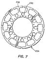
- Fig. 7 shows a thin-plate 23A which forms the stator core 23.
- the thin-plate 23A comprises plural I-shaped split cores 23B on the same circumference.
- a space 23C through which a bolt 28 passes is formed between adjacent split cores.
- Fig. 8 shows the plate 27. Holes 27A which have a seat for the bolt 28 are provided in the plate 27 at positions corresponding to the spaces 23C of the stator core 23.
- the electric rotating machine shown in Fig. 6 is manufactured as follows.
- both the inner circumferential surface and outer circumferential surface are magnetic pole-faces, so the thin plates cannot be fixed by welding.
- the spaces 23C are thus provided in each thin plate 23A and the thin plates 23A are then fixed by passing the bolts 28 through the spaces 23C.
- the thin-plates 23A which form the stator core 23 are stacked, and are fixed to the flange 26 by the bolts 28 together with the plate 27.
- the flange 26 to which the plates 23A and plate 27 are pre-attached are fitted on the chuck 100 of the grinding machine, and then the inner circumferential surface and outer circumferential surface of the stator core 23 are ground with the grindstone 101 by rotating them.
- the inner rotor assembled beforehand is inserted, and attached via a bearing. Also, the outer rotor assembled beforehand is attached to the outside of the stator via a bearing.
- Holes, not shown, are provided for installing permanent magnets in the inner rotor core 21 and the outer rotor core 22, and parts, not shown, are provided for installing coils in the stator core 23.
- the permanent magnets and coils are respectively pre-attached to the rotor cores 21 and 22 or the stator core 23 prior to assembly.
- both the inner and outer circumferential surfaces are magnetic pole-faces, but the inner and outer surfaces are surface-finished when the stator core 23 is fixed only to the flange 26, so machining of the inner surface can be performed easily.
- the magnetic pole-faces can be finished precisely and the gap between cores can also be made small. Moreover, as welding is not used, the magnetic pole-faces are protected.
- Fig. 10 shows a detailed cross section of the electric rotating machine shown in Fig. 6.
- shapes are drawn simplified for ease of understanding.
- the shapes of structural components are different between Fig. 6 and Fig. 10, but components referred to by the same number are identical components.
- the thin plates forming the inner rotor core 21 and outer rotor core 22 are joined by welding, but holes may be opened in the thin plates forming them as in the case of the stator core 23, and they may then be joined by bolts.
- This invention may be applied also to constructions other than those shown in Fig. 1 and Fig. 6.
- this invention may be applied in a similar way to the inner rotor core of an electric rotating machine where the inner rotor core is disposed inside the outer rotor core and the stator core is disposed inside the inner rotor core by forming the inner rotor core in the same manner as shown in Fig. 1 or Fig 3.
Landscapes
- Engineering & Computer Science (AREA)
- Power Engineering (AREA)
- Iron Core Of Rotating Electric Machines (AREA)
- Manufacture Of Motors, Generators (AREA)
Abstract
Description
Claims (9)
- An electric rotating machine, comprising:a middle core (2, 23) comprising plural plates (2A, 23A) stacked in an axial direction,an outer core (3, 22) disposed outside the middle core (2, 23), and which rotates relative to the middle core (2, 23), andan inner core (1, 21) disposed inside the middle core (2, 23), and which rotates relative to the middle core (2, 23),
wherein the plural plates (2A, 23A) are joined to a first fixing member (5, 26) by a connecting member (9, 28). - An electric rotating machine as defined in Claim 1, wherein the connecting member (9, 28) is a bolt, and a hole (2B, 23C) through which the bolt passes is formed in the plural plates (2A, 23A).
- An electric rotating machine as defined in Claim 1, wherein the plates (2A) are ring-shaped thin plates.
- An electric rotating machine as defined in Claim 1, wherein the middle core and inner core are rotor cores, and the outer core is a stator core.
- An electric rotating machine as defined in Claim 1, wherein the middle core is a stator core, and the outer core and inner core are rotor cores.
- An electric rotating machine as defined in Claim 5, wherein the stator core is formed by a plural split core (23B), the connecting member is a bolt, and a space (23C) through which the bolt passes is formed between adjacent split cores.
- A method of manufacturing an electric rotating machine, the machine having a middle core (2, 23) comprising plural plates (2A, 23A) stacked in an axial direction, an outer core (3, 22) disposed outside the middle core (2, 23) which rotates relative to the middle core (2, 23), and an inner core (1, 21) disposed inside the middle core (2, 23) which rotates relative to the middle core (2, 23), and the method comprising:joining the plural plates (2A, 23A) to a first fixing member (5, 26) by a connecting member (9, 28), andfinishing the inner and outer circumferential surfaces of the plural plates (2A, 23A) in the state where the plural plates (2A, 23A) are joined only to the first fixing member (5, 26).
- A method of manufacturing an electric rotating machine as defined in Claim 7, further comprising joining the opposite side of the plural plates (2A) to the first fixing member (5), to a second fixing member (6) after finishing.
- A method of manufacturing an electric rotating machine as defined in Claim 7, wherein the connecting member (9, 28) is a bolt, a hole (2B, 23C) through which the bolt passes is formed in the plural plates (2A, 23A), and the plural plates (2A, 23A) are joined to the first fixing member (5, 26) by passing the bolt through the hole (2B, 23C).
Applications Claiming Priority (2)
| Application Number | Priority Date | Filing Date | Title |
|---|---|---|---|
| JP28235299A JP3580194B2 (en) | 1999-10-04 | 1999-10-04 | Assembly structure of rotating electric machine |
| JP28235299 | 1999-10-04 |
Publications (3)
| Publication Number | Publication Date |
|---|---|
| EP1091475A2 true EP1091475A2 (en) | 2001-04-11 |
| EP1091475A3 EP1091475A3 (en) | 2003-09-24 |
| EP1091475B1 EP1091475B1 (en) | 2006-04-19 |
Family
ID=17651308
Family Applications (1)
| Application Number | Title | Priority Date | Filing Date |
|---|---|---|---|
| EP00121119A Expired - Lifetime EP1091475B1 (en) | 1999-10-04 | 2000-09-28 | Electric rotating machine and manufacturing method thereof |
Country Status (4)
| Country | Link |
|---|---|
| US (1) | US6624545B1 (en) |
| EP (1) | EP1091475B1 (en) |
| JP (1) | JP3580194B2 (en) |
| DE (1) | DE60027381T2 (en) |
Cited By (6)
| Publication number | Priority date | Publication date | Assignee | Title |
|---|---|---|---|---|
| US7259493B2 (en) * | 2003-04-04 | 2007-08-21 | Nissan Motor Co., Ltd. | Stator of two rotor single stator type electric motor |
| DE102007001829A1 (en) * | 2007-01-12 | 2008-07-17 | Siemens Ag | Rotor core assembly for use in e.g. electrical transmission, has free bearings or boreholes and rotor plates held between end pieces with fastening units, which are guided by bearings under precise fitting meshing of blind holes and pins |
| WO2012031694A3 (en) * | 2010-09-07 | 2012-11-15 | Daimler Ag | Rotor of an electrical machine |
| CN103619550A (en) * | 2011-03-31 | 2014-03-05 | 丰田自动车株式会社 | Cutting method, rotor manufacturing method, and cutting device |
| CN103826815A (en) * | 2011-09-28 | 2014-05-28 | Fam公司 | Cutting head assembly for a centrifugal cutting apparatus and centrifugal apparatus equipped with such a cutting head assembly |
| CN104956569A (en) * | 2013-01-29 | 2015-09-30 | 丰田自动车株式会社 | Rotor for rotating electric motor, and rotor manufacturing method |
Families Citing this family (17)
| Publication number | Priority date | Publication date | Assignee | Title |
|---|---|---|---|---|
| US7026742B2 (en) * | 2002-04-01 | 2006-04-11 | Nissan Motor Co., Ltd. | Stator mounting for a double rotor electric motor |
| JP4220324B2 (en) * | 2003-08-01 | 2009-02-04 | 日産自動車株式会社 | Rotating electric machine |
| US20060066171A1 (en) * | 2004-09-28 | 2006-03-30 | Toyo Denso Kabusiki Kaisha | Stator core for rotating electric machine |
| GB2437568B (en) * | 2006-04-24 | 2009-02-11 | Univ Sheffield | Electrical machines |
| EP1860754A1 (en) * | 2006-05-24 | 2007-11-28 | HONDA MOTOR CO., Ltd. | Electric motor |
| JP2008035604A (en) * | 2006-07-27 | 2008-02-14 | Sumitomo Heavy Ind Ltd | Gm freezer, pulse tube freezer, cryopump, mri device, super-conductive magnet system, nmr device, and freezer for cooling of semiconductor |
| KR100793808B1 (en) | 2006-09-07 | 2008-01-11 | 엘지전자 주식회사 | motor |
| WO2008133163A1 (en) | 2007-04-23 | 2008-11-06 | Honda Motor Co., Ltd. | Rotor for rotating machine |
| KR100948103B1 (en) * | 2007-11-20 | 2010-03-17 | 박계정 | Induction motor with multi-stage rotor that can be used as a generator |
| EP2161821B1 (en) * | 2008-09-03 | 2020-06-17 | General Electric Company | Magnetically geared generator |
| JP5678550B2 (en) * | 2010-09-29 | 2015-03-04 | アイシン精機株式会社 | Multi-rotor motor |
| CN105099041A (en) * | 2014-04-22 | 2015-11-25 | 德昌电机(深圳)有限公司 | Brushless motor, external rotor of brushless motor and manufacture method of external rotor |
| US9667126B2 (en) * | 2015-01-05 | 2017-05-30 | Langham Automatic Co., Ltd. | Motor |
| DE102016208259A1 (en) * | 2016-05-13 | 2017-11-16 | Siemens Aktiengesellschaft | Electric machine with double rotor arrangement |
| CN106936278A (en) * | 2017-05-11 | 2017-07-07 | 北京明正维元电机技术有限公司 | A kind of special type permagnetic synchronous motor |
| CN106941305A (en) * | 2017-05-11 | 2017-07-11 | 北京明正维元电机技术有限公司 | A kind of special type permagnetic synchronous motor |
| US12401257B1 (en) * | 2023-05-02 | 2025-08-26 | Wilborn, LLC | Dual armature single field DC motor/generator |
Family Cites Families (12)
| Publication number | Priority date | Publication date | Assignee | Title |
|---|---|---|---|---|
| US3683249A (en) * | 1969-09-27 | 1972-08-08 | Fukuo Shibata | Electric machine arrangement combining electromagnetic coupling with electric rotating machine |
| US3597646A (en) * | 1970-01-26 | 1971-08-03 | Peter John Lawrenson | Dynamoelectric machines |
| DE2332868C2 (en) * | 1973-06-28 | 1975-05-22 | Fa. Arnold Mueller, 7312 Kirchheim | Adjustable three-phase motor with intermediate rotor and internal rotor |
| JPS52146807A (en) * | 1976-06-02 | 1977-12-06 | Hitachi Ltd | Double rotor type motor |
| JPS5315502A (en) * | 1976-07-28 | 1978-02-13 | Hitachi Ltd | Rotary electric machine |
| JPS5441401A (en) * | 1977-09-07 | 1979-04-02 | Hitachi Ltd | Stator core in motor |
| US4564779A (en) * | 1984-09-14 | 1986-01-14 | General Electric Company | Dynamoelectric machine stator using cylindrical keybars |
| JPS6253158A (en) * | 1985-08-29 | 1987-03-07 | Nikki Denso Kk | induction motor |
| EP0798844A1 (en) | 1996-03-28 | 1997-10-01 | Tai-Her Yang | The combined power driven device having a three-layered electromechanical structure with common structures |
| US5793136A (en) * | 1996-06-05 | 1998-08-11 | Redzic; Sabid | Differential motor/generator apparatus |
| AT408045B (en) * | 1998-01-30 | 2001-08-27 | Schroedl Manfred Dipl Ing Dr | ELECTRICAL MACHINE |
| JP3559891B2 (en) * | 1998-06-22 | 2004-09-02 | 日産自動車株式会社 | Cooling structure of multilayer motor |
-
1999
- 1999-10-04 JP JP28235299A patent/JP3580194B2/en not_active Expired - Fee Related
-
2000
- 2000-09-28 EP EP00121119A patent/EP1091475B1/en not_active Expired - Lifetime
- 2000-09-28 DE DE60027381T patent/DE60027381T2/en not_active Expired - Lifetime
- 2000-10-03 US US09/678,311 patent/US6624545B1/en not_active Expired - Lifetime
Cited By (8)
| Publication number | Priority date | Publication date | Assignee | Title |
|---|---|---|---|---|
| US7259493B2 (en) * | 2003-04-04 | 2007-08-21 | Nissan Motor Co., Ltd. | Stator of two rotor single stator type electric motor |
| DE102007001829A1 (en) * | 2007-01-12 | 2008-07-17 | Siemens Ag | Rotor core assembly for use in e.g. electrical transmission, has free bearings or boreholes and rotor plates held between end pieces with fastening units, which are guided by bearings under precise fitting meshing of blind holes and pins |
| WO2012031694A3 (en) * | 2010-09-07 | 2012-11-15 | Daimler Ag | Rotor of an electrical machine |
| CN103619550A (en) * | 2011-03-31 | 2014-03-05 | 丰田自动车株式会社 | Cutting method, rotor manufacturing method, and cutting device |
| CN103619550B (en) * | 2011-03-31 | 2016-07-06 | 丰田自动车株式会社 | Cutting method, rotor manufacturing method, and cutting device |
| CN103826815A (en) * | 2011-09-28 | 2014-05-28 | Fam公司 | Cutting head assembly for a centrifugal cutting apparatus and centrifugal apparatus equipped with such a cutting head assembly |
| CN103826815B (en) * | 2011-09-28 | 2016-06-15 | Fam公司 | Cutting head assembly for a centrifugal cutting apparatus and centrifugal apparatus equipped with such a cutting head assembly |
| CN104956569A (en) * | 2013-01-29 | 2015-09-30 | 丰田自动车株式会社 | Rotor for rotating electric motor, and rotor manufacturing method |
Also Published As
| Publication number | Publication date |
|---|---|
| US6624545B1 (en) | 2003-09-23 |
| DE60027381T2 (en) | 2006-08-31 |
| JP2001112221A (en) | 2001-04-20 |
| JP3580194B2 (en) | 2004-10-20 |
| EP1091475B1 (en) | 2006-04-19 |
| DE60027381D1 (en) | 2006-05-24 |
| EP1091475A3 (en) | 2003-09-24 |
Similar Documents
| Publication | Publication Date | Title |
|---|---|---|
| US6624545B1 (en) | Electric rotating machine and manufacturing method thereof | |
| JP3454234B2 (en) | Split core motor | |
| CN100442637C (en) | Rotor for axial gap motor and manufacturing method thereof | |
| EP2396871B1 (en) | Electric machine - cooling | |
| EP1193827B1 (en) | Rotor structure for permanent-magnet motor | |
| US8884491B2 (en) | Multi-gap electric rotating machine with one-piece stator core | |
| JP3646446B2 (en) | Landel core type rotary electric machine | |
| JP2875497B2 (en) | Motor stator | |
| EP1490950B1 (en) | Electric machine with inner and outer rotor | |
| US6848165B1 (en) | Electric rotating machine and manufacturing method thereof | |
| KR102773680B1 (en) | motor | |
| JP4706397B2 (en) | Rotor for rotating electrical machine and method for manufacturing the same | |
| US20190036390A1 (en) | Stator for rotating electric machine, and rotating electric machine | |
| JP4837334B2 (en) | Permanent magnet rotor | |
| CN111987822A (en) | Stator assembly and motor | |
| JP5924194B2 (en) | Multi-gap rotating electric machine | |
| JP3268762B2 (en) | Rotor of rotating electric machine and method of manufacturing the same | |
| JP2001057747A (en) | Motor laminated core, method of manufacturing the same, and motor | |
| JP2000184643A (en) | Outer rotor of wheel-in motor | |
| US20050110358A1 (en) | Electric rotating machine and manufacturing process thereof | |
| AU2020382759B2 (en) | Improved rotor assemblies for axial flux machines | |
| CN118235313B (en) | Rotor of a synchronous reluctance motor | |
| JPH09289745A (en) | Rotating machine magnetic pole stack | |
| JP5293933B2 (en) | Laminated core of rotor, rotor core, rotor for permanent magnet type synchronous rotating electric machine equipped with the same, permanent magnet type synchronous rotating electric machine, and vehicle, elevator and processing machine using the same | |
| JPH11346446A (en) | Rotating electric machine stator |
Legal Events
| Date | Code | Title | Description |
|---|---|---|---|
| PUAI | Public reference made under article 153(3) epc to a published international application that has entered the european phase |
Free format text: ORIGINAL CODE: 0009012 |
|
| 17P | Request for examination filed |
Effective date: 20000928 |
|
| AK | Designated contracting states |
Kind code of ref document: A2 Designated state(s): AT BE CH CY DE DK ES FI FR GB GR IE IT LI LU MC NL PT SE |
|
| AX | Request for extension of the european patent |
Free format text: AL;LT;LV;MK;RO;SI |
|
| PUAL | Search report despatched |
Free format text: ORIGINAL CODE: 0009013 |
|
| AK | Designated contracting states |
Kind code of ref document: A3 Designated state(s): AT BE CH CY DE DK ES FI FR GB GR IE IT LI LU MC NL PT SE |
|
| AX | Request for extension of the european patent |
Extension state: AL LT LV MK RO SI |
|
| RIC1 | Information provided on ipc code assigned before grant |
Ipc: 7H 02K 15/02 B Ipc: 7H 02K 16/02 A Ipc: 7H 02K 1/18 B |
|
| AKX | Designation fees paid |
Designated state(s): DE FR GB |
|
| 17Q | First examination report despatched |
Effective date: 20040129 |
|
| GRAP | Despatch of communication of intention to grant a patent |
Free format text: ORIGINAL CODE: EPIDOSNIGR1 |
|
| GRAS | Grant fee paid |
Free format text: ORIGINAL CODE: EPIDOSNIGR3 |
|
| GRAA | (expected) grant |
Free format text: ORIGINAL CODE: 0009210 |
|
| AK | Designated contracting states |
Kind code of ref document: B1 Designated state(s): DE FR GB |
|
| REG | Reference to a national code |
Ref country code: GB Ref legal event code: FG4D |
|
| REF | Corresponds to: |
Ref document number: 60027381 Country of ref document: DE Date of ref document: 20060524 Kind code of ref document: P |
|
| ET | Fr: translation filed | ||
| PLBE | No opposition filed within time limit |
Free format text: ORIGINAL CODE: 0009261 |
|
| STAA | Information on the status of an ep patent application or granted ep patent |
Free format text: STATUS: NO OPPOSITION FILED WITHIN TIME LIMIT |
|
| 26N | No opposition filed |
Effective date: 20070122 |
|
| REG | Reference to a national code |
Ref country code: FR Ref legal event code: PLFP Year of fee payment: 17 |
|
| REG | Reference to a national code |
Ref country code: FR Ref legal event code: PLFP Year of fee payment: 18 |
|
| REG | Reference to a national code |
Ref country code: FR Ref legal event code: PLFP Year of fee payment: 19 |
|
| PGFP | Annual fee paid to national office [announced via postgrant information from national office to epo] |
Ref country code: DE Payment date: 20190917 Year of fee payment: 20 Ref country code: FR Payment date: 20190815 Year of fee payment: 20 |
|
| PGFP | Annual fee paid to national office [announced via postgrant information from national office to epo] |
Ref country code: GB Payment date: 20190926 Year of fee payment: 20 |
|
| REG | Reference to a national code |
Ref country code: DE Ref legal event code: R071 Ref document number: 60027381 Country of ref document: DE |
|
| REG | Reference to a national code |
Ref country code: GB Ref legal event code: PE20 Expiry date: 20200927 |
|
| PG25 | Lapsed in a contracting state [announced via postgrant information from national office to epo] |
Ref country code: GB Free format text: LAPSE BECAUSE OF EXPIRATION OF PROTECTION Effective date: 20200927 |