EP1091460A2 - Optical fiber amplifying device - Google Patents
Optical fiber amplifying device Download PDFInfo
- Publication number
- EP1091460A2 EP1091460A2 EP00308763A EP00308763A EP1091460A2 EP 1091460 A2 EP1091460 A2 EP 1091460A2 EP 00308763 A EP00308763 A EP 00308763A EP 00308763 A EP00308763 A EP 00308763A EP 1091460 A2 EP1091460 A2 EP 1091460A2
- Authority
- EP
- European Patent Office
- Prior art keywords
- optical fiber
- amplifying apparatus
- wavelength
- signal light
- signal lights
- Prior art date
- Legal status (The legal status is an assumption and is not a legal conclusion. Google has not performed a legal analysis and makes no representation as to the accuracy of the status listed.)
- Withdrawn
Links
Images







Classifications
-
- H—ELECTRICITY
- H01—ELECTRIC ELEMENTS
- H01S—DEVICES USING THE PROCESS OF LIGHT AMPLIFICATION BY STIMULATED EMISSION OF RADIATION [LASER] TO AMPLIFY OR GENERATE LIGHT; DEVICES USING STIMULATED EMISSION OF ELECTROMAGNETIC RADIATION IN WAVE RANGES OTHER THAN OPTICAL
- H01S3/00—Lasers, i.e. devices using stimulated emission of electromagnetic radiation in the infrared, visible or ultraviolet wave range
- H01S3/05—Construction or shape of optical resonators; Accommodation of active medium therein; Shape of active medium
- H01S3/06—Construction or shape of active medium
- H01S3/063—Waveguide lasers, i.e. whereby the dimensions of the waveguide are of the order of the light wavelength
- H01S3/067—Fibre lasers
- H01S3/06704—Housings; Packages
-
- H—ELECTRICITY
- H01—ELECTRIC ELEMENTS
- H01S—DEVICES USING THE PROCESS OF LIGHT AMPLIFICATION BY STIMULATED EMISSION OF RADIATION [LASER] TO AMPLIFY OR GENERATE LIGHT; DEVICES USING STIMULATED EMISSION OF ELECTROMAGNETIC RADIATION IN WAVE RANGES OTHER THAN OPTICAL
- H01S3/00—Lasers, i.e. devices using stimulated emission of electromagnetic radiation in the infrared, visible or ultraviolet wave range
- H01S3/05—Construction or shape of optical resonators; Accommodation of active medium therein; Shape of active medium
- H01S3/06—Construction or shape of active medium
- H01S3/063—Waveguide lasers, i.e. whereby the dimensions of the waveguide are of the order of the light wavelength
- H01S3/067—Fibre lasers
- H01S3/06754—Fibre amplifiers
-
- H—ELECTRICITY
- H01—ELECTRIC ELEMENTS
- H01S—DEVICES USING THE PROCESS OF LIGHT AMPLIFICATION BY STIMULATED EMISSION OF RADIATION [LASER] TO AMPLIFY OR GENERATE LIGHT; DEVICES USING STIMULATED EMISSION OF ELECTROMAGNETIC RADIATION IN WAVE RANGES OTHER THAN OPTICAL
- H01S3/00—Lasers, i.e. devices using stimulated emission of electromagnetic radiation in the infrared, visible or ultraviolet wave range
- H01S3/10—Controlling the intensity, frequency, phase, polarisation or direction of the emitted radiation, e.g. switching, gating, modulating or demodulating
- H01S3/10007—Controlling the intensity, frequency, phase, polarisation or direction of the emitted radiation, e.g. switching, gating, modulating or demodulating in optical amplifiers
- H01S3/10013—Controlling the intensity, frequency, phase, polarisation or direction of the emitted radiation, e.g. switching, gating, modulating or demodulating in optical amplifiers by controlling the temperature of the active medium
-
- H—ELECTRICITY
- H01—ELECTRIC ELEMENTS
- H01S—DEVICES USING THE PROCESS OF LIGHT AMPLIFICATION BY STIMULATED EMISSION OF RADIATION [LASER] TO AMPLIFY OR GENERATE LIGHT; DEVICES USING STIMULATED EMISSION OF ELECTROMAGNETIC RADIATION IN WAVE RANGES OTHER THAN OPTICAL
- H01S3/00—Lasers, i.e. devices using stimulated emission of electromagnetic radiation in the infrared, visible or ultraviolet wave range
- H01S3/10—Controlling the intensity, frequency, phase, polarisation or direction of the emitted radiation, e.g. switching, gating, modulating or demodulating
- H01S3/13—Stabilisation of laser output parameters, e.g. frequency or amplitude
- H01S3/1301—Stabilisation of laser output parameters, e.g. frequency or amplitude in optical amplifiers
- H01S3/13017—Stabilisation of laser output parameters, e.g. frequency or amplitude in optical amplifiers by controlling the temperature of the active medium
-
- H—ELECTRICITY
- H01—ELECTRIC ELEMENTS
- H01S—DEVICES USING THE PROCESS OF LIGHT AMPLIFICATION BY STIMULATED EMISSION OF RADIATION [LASER] TO AMPLIFY OR GENERATE LIGHT; DEVICES USING STIMULATED EMISSION OF ELECTROMAGNETIC RADIATION IN WAVE RANGES OTHER THAN OPTICAL
- H01S3/00—Lasers, i.e. devices using stimulated emission of electromagnetic radiation in the infrared, visible or ultraviolet wave range
- H01S3/05—Construction or shape of optical resonators; Accommodation of active medium therein; Shape of active medium
- H01S3/06—Construction or shape of active medium
- H01S3/063—Waveguide lasers, i.e. whereby the dimensions of the waveguide are of the order of the light wavelength
- H01S3/067—Fibre lasers
- H01S3/06708—Constructional details of the fibre, e.g. compositions, cross-section, shape or tapering
-
- H—ELECTRICITY
- H01—ELECTRIC ELEMENTS
- H01S—DEVICES USING THE PROCESS OF LIGHT AMPLIFICATION BY STIMULATED EMISSION OF RADIATION [LASER] TO AMPLIFY OR GENERATE LIGHT; DEVICES USING STIMULATED EMISSION OF ELECTROMAGNETIC RADIATION IN WAVE RANGES OTHER THAN OPTICAL
- H01S3/00—Lasers, i.e. devices using stimulated emission of electromagnetic radiation in the infrared, visible or ultraviolet wave range
- H01S3/09—Processes or apparatus for excitation, e.g. pumping
- H01S3/091—Processes or apparatus for excitation, e.g. pumping using optical pumping
- H01S3/094—Processes or apparatus for excitation, e.g. pumping using optical pumping by coherent light
- H01S3/094003—Processes or apparatus for excitation, e.g. pumping using optical pumping by coherent light the pumped medium being a fibre
- H01S3/094011—Processes or apparatus for excitation, e.g. pumping using optical pumping by coherent light the pumped medium being a fibre with bidirectional pumping, i.e. with injection of the pump light from both two ends of the fibre
-
- H—ELECTRICITY
- H01—ELECTRIC ELEMENTS
- H01S—DEVICES USING THE PROCESS OF LIGHT AMPLIFICATION BY STIMULATED EMISSION OF RADIATION [LASER] TO AMPLIFY OR GENERATE LIGHT; DEVICES USING STIMULATED EMISSION OF ELECTROMAGNETIC RADIATION IN WAVE RANGES OTHER THAN OPTICAL
- H01S3/00—Lasers, i.e. devices using stimulated emission of electromagnetic radiation in the infrared, visible or ultraviolet wave range
- H01S3/10—Controlling the intensity, frequency, phase, polarisation or direction of the emitted radiation, e.g. switching, gating, modulating or demodulating
- H01S3/10007—Controlling the intensity, frequency, phase, polarisation or direction of the emitted radiation, e.g. switching, gating, modulating or demodulating in optical amplifiers
- H01S3/10015—Controlling the intensity, frequency, phase, polarisation or direction of the emitted radiation, e.g. switching, gating, modulating or demodulating in optical amplifiers by monitoring or controlling, e.g. attenuating, the input signal
Definitions
- the present invention relates to-an optical fiber amplifying apparatus, and more particularly to an optical fiber amplifying apparatus capable of operating stably against variations in device temperature or in signal light level.
- optical fiber amplifiers applied to a wavelength-multiplex optical transmission system uses a 1550-nm band, commonly known as the C band, and a 1580-nm band, known as the L band, in both of which the wavelength characteristic of the gain is flat in a wide range of wavelengths.
- an optical fiber amplifier using an erbium-doped optical fiber (EDF) as the amplifying optical fiber involves the problem that the gain/wavelength characteristic of the EDF in the L band is heavily dependent on temperature.
- temperature fluctuations in the environment in which such an optical fiber amplifier is installed invite variations in the gain/wavelength characteristic of the optical fiber amplifier. For instance, even if the output level of each of the wavelength multiplex signal lights after amplification is substantially the same and flat, any fluctuation in temperature around the device may give rise to wavelength-dependence in the gain of the optical fiber amplifier, resulting in differences in output level among the individual signal lights after they are amplified.
- An optical fiber amplifying apparatus for directly amplifying the input signal lights, is provided with an optical fiber, preferably an optical fiber doped with some rare earth, for amplifying input signal lights, and a temperature control means for controlling the temperature of the optical fiber.
- the temperature control means can be provided with a temperature sensor for detecting the temperature around the optical fiber, a heating/cooling element for heating or cooling the optical fiber, and a temperature control circuit for controlling the heating/cooling element according to the output of the temperature sensor.
- a temperature sensor for detecting the temperature around the optical fiber
- a heating/cooling element for heating or cooling the optical fiber
- a temperature control circuit for controlling the heating/cooling element according to the output of the temperature sensor.
- an electroconductive film formed over the surface of the optical fiber and a current applying means for flowing an electric current to the electroconductive film can be used.
- the optical fiber amplifier according to the invention is provided with a signal light extracting means for extracting at least one signal light out of the amplified wavelength-multiplex signal lights and a level detecting means for detecting the level of the extracted signal light.
- the temperature control means is provided with a heating/cooling element for heating or cooling the optical fiber and a temperature control circuit for controlling the heating/cooling element according to the level of the detected signal light. The temperature control circuit controls the heating/cooling element so as to keep the level of the signal light at a prescribed value.
- An optical fiber amplifier is preferably provided with, in addition to the signal light extracting means, a signal light extracting means, arranged on the input side of the optical fiber, for extracting at least one signal light out of the amplified wavelength-multiplex signal lights and a level detecting means for detecting the level of the signal light extracted from the signal light extracting means.
- the two signal light extracting means extract signal lights of the same wavelength, and the temperature control circuit controls the heating/cooling element on the basis of the two levels of the extracted signal lights. More specifically, the temperature control circuit computes the gains of the signal lights from the two levels of the signal lights, and controls the heating/cooling element so as to keep the gains at a prescribed value. Where a plurality of signal lights are extracted, the temperature control circuit controls the heating/cooling element so as to equalize the gains of the signal lights. .
- the optical fiber may be in close contact with a bobbin, or a member having a grooved part.
- the heating/cooling element which may be a Peltier element for instance, is arranged in contact with the bobbin or the member.
- the signal light extracting means may be an optical branching unit, consisting of a combination of an optical branching device and an optical filter, a variable-wavelength optical filter, a fiber grating or an arrayed waveguide grating.
- Such an optical fiber amplifying apparatus can operate stably against variations in ambient temperature or in input signal light level.
- an optical fiber amplifier for the L band is provided with an EDF module 5 having an erbium-doped optical fiber 3 (EDF), an exciting light source 4 for supplying an exciting light, and an optical coupler 2 for coupling a signal light and the exciting light.
- EDF erbium-doped optical fiber 3
- an exciting light source 4 for supplying an exciting light
- optical coupler 2 for coupling a signal light and the exciting light.
- optical isolators 1a and 1b are arranged, one each before and after this optical fiber amplifier.
- FIG. 2 is a graph showing the temperature-dependence of the gain/wavelength characteristic of the optical fiber amplifier for the L band according to the prior art. According to this graph, while the gain of the signal light of each wavelength is substantially constant at 25°C, it significantly varies at temperatures of below or above 25°C. As a result, the output level of each signal light after amplification differs from that before amplification in the optical fiber amplifier according to the prior art.
- the optical fiber amplifying apparatus which is the first embodiment of the invention, is provided with an EDF module 5, an exciting light source 4 for supplying an exciting light, an optical wavelength-division multiplexer 2 for introducing the exciting light to the EDF 3, and optical isolators la and 1b for avoiding the influence of any reflected return light.
- the EDF module 5 is provided with an EDF 3 for amplifying a signal light of a 1.55- ⁇ m wavelength band, a Peltier element 7 for heating or cooling the EDF 3, and a thermistor 6 (TH) for detecting the temperature around the EDF 3.
- a temperature control circuit 8 for controlling the temperature of the Peltier element 7 by regulating the current supplied to the element 7 on the basis of the temperature detected by the thermistor 6.
- the temperature control circuit 8 so controls the Peltier element 7 as to keep the monitored value by the thermistor 6 monitoring the temperature of the EDF 3 at a prescribed value. Therefore the control circuit 8 keeps the temperature EDF 3 constant to prevent the gain/wavelength characteristic of the EDF 3 from being varied by any fluctuation in the ambient temperature.
- a signal light of a 1580-nm band comes incident on the optical wavelength-division multiplexer 2 via the optical isolator la.
- an exciting light of a 1480-nm band comes incident on the optical coupler 2 from a laser diode 4 .
- the optical wavelength-division-mutiplexer 2 multiplexes these signal light and exciting light, and delivers the multiplexed light to the EDF 3, which amplifies the signal light and outputs it via the optical isolator 1b.
- the optical wavelength-division mutiplexer 2 can be arranged on the output side of the EDF module 5.
- the exciting light source 4 for supplying the exciting light and the optical wavelength-division multiplexer 2 for introducing the exciting light to the EDF 3 can be arranged either on the output side or the two sides of the EDF module 5.
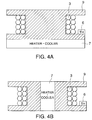
- the EDF 3 is wound around a bobbin 9 built of highly thermo-conductive aluminum, the thermistor 6 is installed on a flange part of the bobbin 9, and the Peltier element 7 is installed in contact with all over the flange of the bobbin 9.
- the EDF 3 is wound doubly around the bobbin 9 in this example, the winding may as well be single, triple or more.
- a bobbin 9 with no flange can also be used.
- the bobbin 9 is cylindrically shaped, and the Peltier element 7 is installed within the cylindrical bobbin.
- the EDF 3 is housed in a groove formed in a member 10 built of highly thermo-conductive aluminum, and the inside of the groove is filled with silicon grease 11.
- the thermistor 6 is mounted in the silicon grease 11 together with the EDF 3, and the Peltier element 7 is installed in contact with a side of this member 10. Since the EDF 3 and the thermistor 6 are mounted in the highly thermo-conductive silicon grease filling the groove in the member 10, -the accuracy of temperature monitoring is enhanced.
- the groove in which the EDF 3 is housed may be, for instance, circular or oval in cross section, and the EDF 3 is wound around a member within this groove.
- the Peltier element 7 heats or cools the EDF 3 via the bobbin 9 or the member 10.
- the bobbins in the examples of FIGs. 4A and 4B and the member in the example of FIG. 5 may be built of some other metallic or non-metallic highly thermo-conductive material than aluminum.
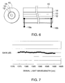
- the EDF 3 is provided with an optically transmissive core 12 and clad 13, and a carbon film 14 and acrylate resin 15 for securing a sufficient bending strength.
- This carbon film 14 is fitted with electrodes 16a and 16b for flowing an electric current to the carbon film.
- These EDF 3 and thermistor 6 can be housed in the bobbin 9 or a case 10 illustrated in, for example, FIG. 2 or 3.
- the EDF 3 is optimized to so as to have the flattest gain/wavelength characteristic at the target level of temperature control.
- the temperature sensor may be a usual thermocouple.
- a device capable of cooling alone can as well be used instead of a heater/cooler.
- a thin metallic film or a resistance film may be used as well.
- the gain/wavelength characteristic (relationship between wavelength and gain) of the optical fiber amplifying apparatus of any specific example described above is such that, when the temperature of the EDF 3 is around 25°C, the variation range of the gain is about 1 dB in the wavelength range of 1570 nm to 1605 nm.
- the resistance of the thermistor 6 fitted to the EDF module 5 drops.
- the temperature control circuit 8 detects the higher temperature of the EDF 3 than 25°C, and flows a drive current in the cooling direction to the Peltier element 7 to control the temperature of the EDF 3.
- the resistance of the thermistor 6 fitted to the EDF module 5 rises. Then the temperature control circuit 8 detects the lower temperature of the EDF 3 than 25°C, and flows a drive current in the heating direction to the Peltier element 7 to control the temperature of the EDF 3.
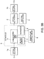
- an optical fiber amplifying apparatus which is a second preferred embodiment of the present invention, particularly intended for wavelength-multiplex signal lights, heats or cools the EDF 3 on the basis of the output level of a specific signal light out of the wavelength-multiplex signal lights.
- This optical fiber amplifying apparatus is provided with an optical branching device (e.g., optical coupler) 17 for branching part of the wavelength-multiplex signal lights.
- an optical branching device e.g., optical coupler
- To the branching port of the branching device is connected a channel monitor 18 for extracting a signal light of a specific wavelength out of the branched wavelength-multiplex signal lights and detecting the output level of the signal light.
- the channel monitor 18 delivers the output level of the detected signal light to the control circuit 19 as the monitoring signal.
- the control circuit 19 analyzes the monitoring signal from the channel monitor 18, and controls the Peltier element 7 of the EDF module 5 so as to maximize the flatness of the wavelength characteristic of the output level from the optical fiber amplifying apparatus.
- the output level of this signal light at the time the wavelength characteristic becomes the flattest, i.e. the output level of the control target, is preset in the control circuit 19.
- the channel monitor 18, using an optical band pass filter for selectively extracting a signal of a predetermined wavelength (channel) out of the wavelength-multiplex signals monitors the signal light of the pertinent wavelength.
- the EDF module 5 has no thermistor.
- an optical fiber amplifying apparatus which is a third preferred embodiment of the invention, a plurality of signal lights contained in amplified wavelength-multiplex signal lights are extracted, and control is so effected that the output level of each signal light contained in these wavelength-multiplex signal lights be kept within a prescribed range.
- FIG. 9 illustrates a case in which signal lights of two wavelengths (e.g., a signal light of 1580 nm in wavelength and another of 1590 nm in wavelength) are wavelength-multiplexed.
- This optical fiber amplifying apparatus is provided, following the optical isolator 1b, with an optical branching device 17 for branching part of the amplified wavelength-multiplex signal lights.
- An optical branching device 20 connected to the optical branching device 17, branches the wavelength-multiplex signal lights into the number of signal slights (two in this embodiment) contained in the wavelength-multiplex signal lights.
- Optical filters 21a and 21b extract signal lights of respectively specific wavelengths (a wavelength of 1580 nm and a wavelength of 1590 nm). These signal lights are converted into amperages by photodiodes 22a and 22b, respectively, and further converted into voltages by amperage-to-voltage converters 23a and 23b, respectively.
- An amplifying circuit 24 amplifies the difference between the voltages respectively supplied by the amperage-to-voltage converters 23a and 23b (i.e. the output levels of the signal lights of the two wavelengths), and delivers it to a driver circuit 25.
- the driver circuit 25 controls the Peltier element 7 to reduce the voltage difference. Since in this third embodiment the level difference between signal lights is directly detected and controlled, the output levels of individual signal lights can be flattened even if the overall input level of the signal lights varies or the output levels are actively varied by altering the gain. Where three or more signal lights are extracted from the wavelength-multiplex signal lights, the driver circuit 25 can control the Peltier element 7 as described above by using the levels of two, three or more specific signal lights (i.e. voltages). The control circuit 25 can effect control so as to keep the levels of the plurality'of signal lights within a prescribed range.
- wavelength-multiplex signal lights are branched on the input side and the output side of the EDF module 5, and signal lights of the same wavelength are extracted.
- the control circuit 19 computes the gains from the input level and the output level of the signal lights of that wavelength, and so controls the Peltier element 7 as to keep the gains at a prescribed value.
- the optical fiber amplifier of FIG. 10 is provided with an optical branching device 26 for branching part of the wavelength-multiplex signal lights to the signal light input side of the optical isolator 1a. To the branching port of the optical branching device 26 is connected the channel monitor 27.
- the channel monitor 27 extracts signal lights of a specific wavelength out of the branched wavelength-multiplex signal lights, detects the output level of the signal lights, and delivers it to the control circuit 19 as the monitoring signal.
- This optical fiber amplifier is also provided on its output side with another optical branching device 17 and channel monitor 18.
- the channel monitor 18 delivers to the control circuit 19 the level of signal lights of the same wavelength as that of the signal lights extracted by the channel monitor 27.
- the control circuit 19 calculates the gains on the basis of the received input signal light level and output signal light level. The control circuit 19 so controls the Peltier element 7 as to keep the calculated gains at a prescribed value.
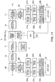
- an optical fiber amplifying apparatus which is a fifth preferred embodiment of the invention, like the fourth embodiment, a plurality of signal lights among the wavelength-multiplex signal lights are monitored, and the gains of signal lights are computed to control the temperature of the Peltier element 7.
- the optical fiber amplifying apparatus of FIG. 11 is provided on the signal light input side of the optical isolator la with an optical branching device 28 for branching part of the wavelength-multiplex signal lights.
- an optical branching device 29 To the branching port of the optical branching device 28 is connected an optical branching device 29.
- the optical branching device 29 further branches the branched wavelength-multiplex signal lights into two.
- Optical filters 30a and 30b selectively extract only signal lights out of the two branched lights.
- Photodiodes 31a and 31b and amperage-to-voltage converters 32a and 32b convert the levels of the two signal lights into voltages.
- An amplifier 33 amplifies the voltages, and delivers them to the driver circuit 25.
- the optical fiber amplifying apparatus in this example is provided on the output side of the EDF module 5 with the configuration illustrated in FIG. 9. Therefore, the driver circuit 25 receives voltage signals indicating the output levels of signal lights from the output side, and computes the gains from the input/output levels of the signal lights.
- the driver circuit 25 so controls the Peltier element 7 as to keep the gains of the signal lights within a prescribed range (e. g. within 1 dB). While this example is an instance in which wavelength-multiplex signal lights contain two signal lights, if more optical filters are added, naturally more signal lights are processed.
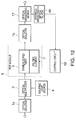
- a variable-wavelength optical filter 40 can successively monitor a signal light of each wavelength (channel) out of wavelength-multiplex signal lights by varying the transmissible wavelength band of the optical filter.
- the control circuit 19 can temporarily hold the output level of each of the monitored signal lights in a memory (not shown), and control the Peltier element 7 on the basis of the output level of each signal light.
- Another signal light extracting means can have, as illustrated in FIG. 13, a first optical branching device for branching wavelength-multiplex signal lights and an optical demultiplexer 50 (e.g.
- an arrayed waveguide grating for demultiplexing the branched wavelength-multiplex signal-lights into individual signal lights.
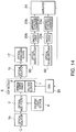
- Still another signal light extracting means can have a configuration in which optical demultiplexers 60, each combining a fiber grating reflecting only a specific wavelength and transmitting all other wavelengths and an optical circulator, are connected in cascade.
- Such wavelength extracting means can be arranged on either the output side or both sides of the EDF module.
- An optical fiber amplifying apparatus can prevent the gain/wavelength characteristic from being varied by fluctuations in ambient temperature.
- the optical fiber amplifying apparatus as it extracts signal lights out of wavelength-multiplex signal flights and controls the heating/cooling of the EDF module according to their output levels, can flatten the output level or gains of the signal lights.
Landscapes
- Physics & Mathematics (AREA)
- Electromagnetism (AREA)
- Engineering & Computer Science (AREA)
- Plasma & Fusion (AREA)
- Optics & Photonics (AREA)
- Microelectronics & Electronic Packaging (AREA)
- Lasers (AREA)
Abstract
Description
Claims (13)
- An optical fiber amplifying apparatus for directly amplifying input signal lights, comprising:an optical fiber for amplifying input signal lights, anda temperature control means for controlling the temperature of the optical fiber.
- An optical fiber amplifying apparatus, as claimed in Claim 1, wherein
said temperature control means comprises:a temperature sensor for detecting the temperature in the vicinity of said optical fiber,a heating/cooling element for heating or cooling said optical fiber, anda temperature control circuit for controlling the heating/cooling element on the basis of the output of the temperature sensor. - An optical fiber amplifying apparatus, as claimed in Claim 2, wherein
said temperature control means is provided with:a bobbin in which said optical fiber is to be installed, andsaid heating/cooling element is arranged in contact with the bobbin. - An optical fiber amplifying apparatus, as claimed in Claim 3, whereinsaid bobbin has a columnar shape having a flange at each end, andsaid optical fiber is wound around said bobbin between the flanges.
- An optical fiber amplifying apparatus, as claimed in Claim 4, wherein
said heating/cooling element is arranged to be in contract with at least one of the flanges of said bobbin. - An optical fiber amplifying apparatus, as claimed in Claim 3, whereinsaid bobbin is in a cylindrical shape having a hollow part, andsaid heating/cooling element is arranged in the hollow part of said bobbin.
- An optical fiber amplifying apparatus, as claimed in Claim 2, whereinsaid temperature control means is provided with a member having a grooved part and an optical fiber is arranged in the grooved part so as to be in close contact with the member, andsaid heating/cooling element is arranged in contact with the member.
- An optical fiber amplifying apparatus, as claimed in Claim 1, wherein
said temperature control means is provided with:a temperature sensor for detecting the temperature in the vicinity of said optical fiber,an electroconductive film formed over the surface of said optical fiber,a current applying means for flowing an electric current to the electroconductive film, anda control circuit for controlling the current applying means on the basis of the output of the temperature sensor. - An optical fiber amplifying apparatus, as claimed in Claim 8, wherein
said electroconductive film is a carbon film. - An optical fiber amplifying apparatus, as claimed in Claim 1, provided with:an exciting light source for supplying an exciting light, andan optical mupltiplexer for bringing the exciting light incident on said optical fiber, whereinthe optical mupltiplexer is arranged on the signal light input side of said optical fiber, andthe exciting light comes incident on said optical fiber in the same direction as the traveling direction of the signal light.
- An optical fiber amplifying apparatus, as claimed in Claim 1, provided with:an exciting light source for supplying an exciting light, andan optical multiplexer for bringing the exciting light incident on said optical fiber, whereinthe optical multiplexer is arranged on the signal light output side of said optical fiber, andthe exciting light comes incident on said optical fiber in the reverse direction to the traveling direction of the signal light.
- An optical fiber amplifying apparatus, as claimed in Claim 1, provided with:an exciting light source for supplying an exciting light, andoptical mupltiplexers for bringing the exciting light incident on said optical fiber, whereinthe optical mupltiplexers are arranged on the signal light input side and the signal light output side of said optical fiber, andthe exciting light comes incident on said optical fiber in two directions.
- An optical fiber amplifying apparatus, as claimed in Claim 1, provided with:said temperature control means is provided with:a signal light extracting means for extracting at least one signal light out of wavelength-multiplex signal lights supplied from said optical fiber, anda level detecting means for detecting the level(s) of the extracted signal light(s), whereina heating/cooling element for heating or cooling said optical fiber, anda temperature control circuit for controlling the heating/cooling element on the basis of the level(s) of the detected signal light(s).14. An optical fiber amplifying apparatus, as claimed in Claim 13, whereinsaid signal light extracting means detects one signal light out of the wavelength-multiplex signal lights, andsaid temperature control circuit so controls said heating/cooling element as to keep the level of that signal light at a prescribed value.15. An optical fiber amplifying apparatus, as claimed in Claim 13, whereinsaid signal light extracting means extracts a plurality of signal lights differing in wavelength out of the wavelength-multiplex signal lights,said level detecting means detects the output levels of the plurality of extracted signal lights, andsaid temperature control circuit so controls said heating/cooling element as to keep the levels of these signal lights within a prescribed range.16. An optical fiber amplifying apparatus, as claimed in Claim 15, wherein
said plurality of signal lights are all the signal lights contained in the wavelength-multiplex signal lights.17. An optical fiber amplifying apparatus, as claimed in Claim 13, wherein
said signal light extracting means includes:a first optical branching device, arranged on the output side of said optical fiber, for branching said wavelength-multiplex signal lights which have been amplified,a first optical demultiplexing device for demultiplexing the branched wavelength-multiplex signal lights into a plurality of signal lights.18. An optical fiber amplifying apparatus, as claimed in Claim 13, wherein
said signal light extracting means includes:a first optical branching device, arranged on the output side of said optical fiber, for branching said wavelength-multiplex signal lights which have been amplified,a second optical branching device for branching the branched wavelength-multiplex signal lights into a plurality of branched lights, andan optical filter, arranged on the output side of the second optical branching device, for extracting a signal light of a prescribed wavelength out of each branched light.19. An optical fiber amplifying apparatus, as claimed in Claim 13, wherein
said signal light extracting means includes:
a plurality of optical demultiplexers, arranged in series on the output side of said optical fiber, for selectively branching and outputting signal lights differing in wavelength successively out of said wavelength-multiplex signal lights which have been amplified.20. An optical fiber amplifying apparatus, as claimed in Claim 13, wherein
said signal light extracting means includes:a first optical branching device, arranged on the output side of said optical fiber, for selectively branching said wavelength-multiplex signal lights which have been amplified, anda variable-wavelength optical filter for successively extracting a signal light of each wavelength out of the branched wavelength-multiplex signal lights.21. An optical fiber amplifying apparatus, as claimed in Claim 13, further provided with:signal light extracting means, arranged on the input side of said optical fiber, for extracting at least one signal light out of the inputted wavelength-multiplex signal lights, anda level detecting means for detecting the level(s) of the signal light(s) extracted from the signal light extracting means, whereinthe two signal light extracting means extract signal lights of the same wavelength, andsaid temperature control circuit controls the heating/cooling element on the basis of the input levels and the output levels of the extracted signal lights of the same wavelength.22. An optical fiber amplifying apparatus, as claimed in Claim 21, whereinthe two signal light extracting means extract one signal light each of the same wavelength, andsaid temperature control circuit computes the gain of the signal light on the basis of said two levels of the signal lights and so controls the heating/cooling element as to keep the gain at a prescribed value.23. An optical fiber amplifying apparatus, as claimed in Claim 21, whereinthe two signal light extracting means extract a plurality of signal light of the same wavelength, and,said temperature control circuit computes the gains of the signal lights on the basis of said two levels of the signal lights of the same wavelength and so controls said heating/cooling element as to keep these gains within a prescribed range.24. An optical fiber amplifying apparatus, as claimed in Claim 13, whereinsaid temperature control means is provided with a bobbin around which said optical fiber is wound, andsaid heating/cooling element is arranged in contact with the bobbin.25. An optical fiber amplifying apparatus, as claimed in Claim 24, whereinsaid bobbin has a columnar shape having a flange at each end, andsaid optical fiber is wound around said bobbin between the flanges.26. An optical fiber amplifying apparatus, as claimed in Claim 25, wherein
said heating/cooling element is arranged to be in contact with at least one of the flanges of said bobbin.27. An optical fiber amplifying apparatus, as claimed in Claim 24, whereinsaid bobbin is in a cylindrical shape having a hollow part, andsaid heating/cooling element is arranged in the hollow part of said bobbin.28. An optical fiber amplifying apparatus, as claimed in Claim 13, whereinsaid temperature control means is provided with a member having a grooved part and an optical fiber is arranged in the grooved part so as to be in close contact with the member, andsaid heating/cooling element is arranged in contact with the member.29. An optical fiber amplifying apparatus, as claimed in Claim 13, wherein
said heating/cooling element is provided with:an electroconductive film formed over the surface of said optical fiber, anda current applying means for flowing an electric current to the electroconductive film, andsaid temperature control circuit controls the current applying means on the basis of the output of the level of the detected signal light.30. An optical fiber amplifying apparatus, as claimed in Claim 29, wherein
said electroconductive film is a carbon film.
Applications Claiming Priority (2)
| Application Number | Priority Date | Filing Date | Title |
|---|---|---|---|
| JP28261199A JP3449316B2 (en) | 1999-10-04 | 1999-10-04 | Optical fiber amplifier |
| JP28261199 | 1999-10-04 |
Publications (2)
| Publication Number | Publication Date |
|---|---|
| EP1091460A2 true EP1091460A2 (en) | 2001-04-11 |
| EP1091460A3 EP1091460A3 (en) | 2001-08-16 |
Family
ID=17654779
Family Applications (1)
| Application Number | Title | Priority Date | Filing Date |
|---|---|---|---|
| EP00308763A Withdrawn EP1091460A3 (en) | 1999-10-04 | 2000-10-04 | Optical fiber amplifying device |
Country Status (3)
| Country | Link |
|---|---|
| US (1) | US6621623B1 (en) |
| EP (1) | EP1091460A3 (en) |
| JP (1) | JP3449316B2 (en) |
Cited By (1)
| Publication number | Priority date | Publication date | Assignee | Title |
|---|---|---|---|---|
| EP1335457B1 (en) * | 2002-01-08 | 2006-07-12 | Diehl BGT Defence GmbH & Co.KG | Ladar system for flying vehicle |
Families Citing this family (14)
| Publication number | Priority date | Publication date | Assignee | Title |
|---|---|---|---|---|
| JP2001257402A (en) | 2000-03-08 | 2001-09-21 | Nec Corp | Optical amplification medium component and optical fiber amplifier provided therewith |
| GB0124258D0 (en) * | 2001-10-09 | 2001-11-28 | Marconi Comm Ltd | Optical amplifier control in WDM communications systems |
| US7525725B2 (en) * | 2002-03-05 | 2009-04-28 | Sumitomo Electric Industries, Ltd. | Optical amplification module, optical amplifier, optical communication system, and white light source |
| JP3961487B2 (en) | 2002-04-19 | 2007-08-22 | 富士通株式会社 | Rare earth doped optical fiber module and manufacturing method thereof |
| WO2005031401A2 (en) * | 2003-09-25 | 2005-04-07 | Nufern | Apparatus and methods for accommodating loops of optical fiber |
| US20050068612A1 (en) * | 2003-09-30 | 2005-03-31 | Gordon Wilson | Pre-programmable optical filtering / amplifying method and apparatus |
| JP2005150435A (en) * | 2003-11-17 | 2005-06-09 | Fujitsu Ltd | Optical amplifier and optical amplifier control method |
| JP2007158013A (en) * | 2005-12-05 | 2007-06-21 | Hamamatsu Photonics Kk | Optical fiber structure and optical device |
| JP4969840B2 (en) * | 2005-12-05 | 2012-07-04 | 浜松ホトニクス株式会社 | Optical fiber structure and optical device |
| EP2043204B1 (en) * | 2006-07-19 | 2016-05-04 | Nikon Corporation | Cassette for optical fiber amplifier, optical fiber amplifier and light source device |
| JP4877009B2 (en) * | 2007-03-28 | 2012-02-15 | 日本電気株式会社 | Optical direct amplifier for WDM optical transmission |
| JP5169036B2 (en) * | 2007-06-21 | 2013-03-27 | 富士通株式会社 | Optical fiber reel, optical fiber mounting method, and optical module |
| CN103155309B (en) * | 2010-10-29 | 2016-06-01 | 古河电气工业株式会社 | Optical amplification device and light conveying system |
| JP5884654B2 (en) * | 2012-06-12 | 2016-03-15 | 富士通株式会社 | Optical amplifier and optical amplifier control method |
Family Cites Families (9)
| Publication number | Priority date | Publication date | Assignee | Title |
|---|---|---|---|---|
| JPH0411794A (en) | 1990-04-28 | 1992-01-16 | Furukawa Electric Co Ltd:The | Fiber type optical amplifier |
| JPH085860A (en) | 1994-06-22 | 1996-01-12 | Shin Etsu Chem Co Ltd | Rare earth element-doped optical fiber type optical amplifier |
| JPH09246638A (en) | 1996-03-01 | 1997-09-19 | Nippon Telegr & Teleph Corp <Ntt> | Mode-locked fiber laser operation stabilization method |
| WO2000001101A2 (en) * | 1998-06-30 | 2000-01-06 | Corning Incorporated | Thermal tuning of optical amplifiers in wdm systems |
| JP2000091674A (en) | 1998-09-10 | 2000-03-31 | Nippon Telegr & Teleph Corp <Ntt> | Optical amplifier |
| JP3688131B2 (en) | 1998-09-10 | 2005-08-24 | 日本電信電話株式会社 | Optical amplification element |
| JP2000277842A (en) | 1999-03-23 | 2000-10-06 | Oki Electric Ind Co Ltd | Optical components, and optical amplifier and characteristics control method for the same |
| JP3903650B2 (en) | 1999-06-18 | 2007-04-11 | 住友電気工業株式会社 | Optical amplifier and optical amplifier control method |
| US6351583B1 (en) * | 2000-01-28 | 2002-02-26 | Agere Systems Guardian Corp. | Multiple laser wavelength stabilization |
-
1999
- 1999-10-04 JP JP28261199A patent/JP3449316B2/en not_active Expired - Lifetime
-
2000
- 2000-10-02 US US09/676,560 patent/US6621623B1/en not_active Expired - Lifetime
- 2000-10-04 EP EP00308763A patent/EP1091460A3/en not_active Withdrawn
Cited By (1)
| Publication number | Priority date | Publication date | Assignee | Title |
|---|---|---|---|---|
| EP1335457B1 (en) * | 2002-01-08 | 2006-07-12 | Diehl BGT Defence GmbH & Co.KG | Ladar system for flying vehicle |
Also Published As
| Publication number | Publication date |
|---|---|
| JP3449316B2 (en) | 2003-09-22 |
| JP2001111150A (en) | 2001-04-20 |
| US6621623B1 (en) | 2003-09-16 |
| EP1091460A3 (en) | 2001-08-16 |
Similar Documents
| Publication | Publication Date | Title |
|---|---|---|
| US6621623B1 (en) | Optical fiber amplifying device stabilized for temperature and signal level | |
| EP1158631A2 (en) | Semiconductor laser apparatus | |
| KR100417322B1 (en) | Optical amplifier and a method of controlling the optical amplifier | |
| US6567600B2 (en) | Optical amplifying medium component and optical fiber amplifier having the same | |
| JPH1187812A (en) | Gain equalizer and optical transmission system provided with the gain equalizer | |
| US6996142B2 (en) | Light source device and wavelength control device therefor | |
| US6522459B1 (en) | Temperature control and monitoring of optical detector components in an optical communication system | |
| JP2000277842A (en) | Optical components, and optical amplifier and characteristics control method for the same | |
| US6233078B1 (en) | Photo signal amplification transmission system | |
| US20120188631A1 (en) | Optical amplification apparatus | |
| JP3585758B2 (en) | Method for gain equalization and apparatus and system used to implement the method | |
| US6867907B2 (en) | Pumping light source unit, raman amplifier, and optical transmission system | |
| US7911684B1 (en) | Variable gain erbium doped fiber amplifier | |
| KR20020074221A (en) | Wavelength dispersion compensation module and optical transmission system including the same | |
| US6704137B2 (en) | Optical amplifier, method for optical amplification and optical transmission system | |
| US7336415B2 (en) | Optical amplification module, optical amplification apparatus, and optical communications system | |
| US9306362B2 (en) | Optical branching device, optical amplification apparatus, and optical amplification method | |
| JP2710199B2 (en) | Optical fiber amplifier for WDM transmission | |
| US20030039277A1 (en) | Semiconductor laser apparatus and semiconductor laser module | |
| KR100236832B1 (en) | Transmission apparatus and implementation method having wavelength stabilizer in wavelength division multiplexing | |
| US7027215B2 (en) | Optical component, optical amplification module, and optical transmission system | |
| EP1313235B1 (en) | Optical amplifier and optical communication system including the same | |
| JP2013026295A (en) | Optical amplifier and controlling method thereof | |
| JPH11234246A (en) | Optical transmission system and optical transmitter used in the optical transmission system | |
| JPH11289299A (en) | Level supervisory control method for wavelength multiple signal light, wavelength multiple optical transmitting terminal station device and relaying device |
Legal Events
| Date | Code | Title | Description |
|---|---|---|---|
| PUAI | Public reference made under article 153(3) epc to a published international application that has entered the european phase |
Free format text: ORIGINAL CODE: 0009012 |
|
| AK | Designated contracting states |
Kind code of ref document: A2 Designated state(s): FR GB IT |
|
| AX | Request for extension of the european patent |
Free format text: AL;LT;LV;MK;RO;SI |
|
| PUAL | Search report despatched |
Free format text: ORIGINAL CODE: 0009013 |
|
| AK | Designated contracting states |
Kind code of ref document: A3 Designated state(s): AT BE CH CY DE DK ES FI FR GB GR IE IT LI LU MC NL PT SE |
|
| AX | Request for extension of the european patent |
Free format text: AL;LT;LV;MK;RO;SI |
|
| RIC1 | Information provided on ipc code assigned before grant |
Free format text: 7H 01S 3/102 A, 7H 01S 3/067 B |
|
| 17P | Request for examination filed |
Effective date: 20010910 |
|
| AKX | Designation fees paid |
Free format text: FR GB IT |
|
| REG | Reference to a national code |
Ref country code: DE Ref legal event code: 8566 |
|
| STAA | Information on the status of an ep patent application or granted ep patent |
Free format text: STATUS: THE APPLICATION IS DEEMED TO BE WITHDRAWN |
|
| 18D | Application deemed to be withdrawn |
Effective date: 20060718 |