EP1091453A2 - Connector - Google Patents
Connector Download PDFInfo
- Publication number
- EP1091453A2 EP1091453A2 EP00308730A EP00308730A EP1091453A2 EP 1091453 A2 EP1091453 A2 EP 1091453A2 EP 00308730 A EP00308730 A EP 00308730A EP 00308730 A EP00308730 A EP 00308730A EP 1091453 A2 EP1091453 A2 EP 1091453A2
- Authority
- EP
- European Patent Office
- Prior art keywords
- flange
- housings
- sealing ring
- connector according
- connector
- Prior art date
- Legal status (The legal status is an assumption and is not a legal conclusion. Google has not performed a legal analysis and makes no representation as to the accuracy of the status listed.)
- Granted
Links
Images
Classifications
-
- H—ELECTRICITY
- H01—ELECTRIC ELEMENTS
- H01R—ELECTRICALLY-CONDUCTIVE CONNECTIONS; STRUCTURAL ASSOCIATIONS OF A PLURALITY OF MUTUALLY-INSULATED ELECTRICAL CONNECTING ELEMENTS; COUPLING DEVICES; CURRENT COLLECTORS
- H01R13/00—Details of coupling devices of the kinds covered by groups H01R12/70 or H01R24/00 - H01R33/00
- H01R13/46—Bases; Cases
- H01R13/533—Bases, cases made for use in extreme conditions, e.g. high temperature, radiation, vibration, corrosive environment, pressure
-
- H—ELECTRICITY
- H01—ELECTRIC ELEMENTS
- H01R—ELECTRICALLY-CONDUCTIVE CONNECTIONS; STRUCTURAL ASSOCIATIONS OF A PLURALITY OF MUTUALLY-INSULATED ELECTRICAL CONNECTING ELEMENTS; COUPLING DEVICES; CURRENT COLLECTORS
- H01R13/00—Details of coupling devices of the kinds covered by groups H01R12/70 or H01R24/00 - H01R33/00
- H01R13/46—Bases; Cases
- H01R13/52—Dustproof, splashproof, drip-proof, waterproof, or flameproof cases
- H01R13/5219—Sealing means between coupling parts, e.g. interfacial seal
-
- H—ELECTRICITY
- H01—ELECTRIC ELEMENTS
- H01R—ELECTRICALLY-CONDUCTIVE CONNECTIONS; STRUCTURAL ASSOCIATIONS OF A PLURALITY OF MUTUALLY-INSULATED ELECTRICAL CONNECTING ELEMENTS; COUPLING DEVICES; CURRENT COLLECTORS
- H01R13/00—Details of coupling devices of the kinds covered by groups H01R12/70 or H01R24/00 - H01R33/00
- H01R13/62—Means for facilitating engagement or disengagement of coupling parts or for holding them in engagement
- H01R13/627—Snap or like fastening
- H01R13/6271—Latching means integral with the housing
- H01R13/6272—Latching means integral with the housing comprising a single latching arm
Definitions
- the present invention relates to an electrical connector provided with a means to prevent terminal fittings from rubbing against each other and becoming abraded.
- a conventional connector is configured so as to be provided with a pair of male and female connector housings, each having terminal fittings attached thereto, one of these connector housings having a locking arm capable of being resiliently inclined, this locking arm having a stopped member.
- the locking arm is inclined; the male and female terminal fittings then reach a correct fitted state and make contact, the locking arm returns to its original position. And the stopped member thereof engages with a stopping member of the corresponding housing. The two connector housings are thereby maintained in a fitted state.
- the locking mechanism is provided with the inclinable locking arm which, in order to be inclined above or below the corresponding stopping member, needs a specified clearance between the stopped member of the locking arm and the corresponding stopping member. If this clearance is provided, there is the problem that the two housings rattle against each other if they are installed in a location prone to vibration from the exterior, contacting members of the male and female terminal fittings repeatedly rub against one another, and this causes damage such as contacting members gradually being abraded and their contacting force decreasing.
- a means to prevent rattling between the male and female housings, so as to prevent the terminal fittings from rubbing against each other and becoming abraded, has been set forth by the present applicant in Japanese Utility Model Registration Number 2542630.
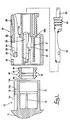
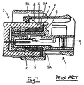
- a sealing ring 5 is attached between a terminal housing 2 of a female housing 1 and a hood member 4 of a male housing 3.
- a flange 5A is provided on a posterior outer circumference of the sealing ring 5, this flange 5A fitting between an anterior edge of the hood member 4 and a protruding wall 6 of the female housing 1, this protruding wall 6 being opposite the anterior edge of the hood member 4.
- the returning force of the flange 5A causes the two housings 1 and 3 to move in a direction of separation, and a stopped member 7A of a locking arm 7 fits tightly with a stopping member 8, thereby preventing the male and female housings 1 and 3 from vibrating against each other.
- the flange 5A of the sealing is simply squeezed between the hood member 4 and the protruding wall 6. Consequently, when the flange 5A receives a pushing force, the outer edge thereof moves outwards, and since the pushing force onto the terminal housing 2 is weakened at a posterior edge of the sealing ring 5, the amount of resilient strength which is exercised may be insufficient, and the seal may be damaged.
- a protrusion 9 protrudes from the protruding wall 6, this protrusion 9 approaching a cut-away member 9A formed in the flange 5A.
- the anterior edge of the hood member 4 makes contact with the protrusion 9 and prevents further movement in the anterior direction, thereby preventing the flange 5A from being overly compressed.
- this configuration has the problem of being somewhat complex, and an improved solution is required.
- the present invention aims to provide the required improvement.
- an electrical connector comprising a pair of connector housings adapted for mutual fitting together in a fitting direction, one of said housings having a resilient locking arm adapted to engage the other of said housings to maintain said housings in a fitted state, and a resilient sealing ring being provided between respective circumferential faces of said housings, charactertised in that said sealing ring has a continuous radially outwardly extending flange adapted to be gripped between opposed faces of said connector housings in the fitted condition, one of the sealing ring and connector housings having a pushing surface at an angle to said fitting direction and adapted to urge the outer edge of said flange radially inwardly.
- the pushing surface is provided on the sealing ring and faces said other housing.
- the pushing surface may be flat or acruate.
- the pushing surface may alternatively be provided on one or other of said connector housings.
- the sealing ring preferably has a tubular portion insertable in a corresponding aperture of one of said housings.
- the tubular portion may have outer peripheral sealing lips, and internal grooves to improve sealing thereof in said aperture.
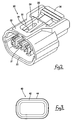
- a waterproof connector is provided with a male connector housing 10 (hereafter referred to simply as male housing) and a female connector housing 20 (hereafter referred to simply as female housing), these male and female housings 10 and 20 fitting mutually together.
- male and female housings 10 and 20 fitting mutually together.
- fitting sides of the male and female housings are designated as the anterior.
- the male housing 10 is formed in a unified manner with an electrical device 11, this male housing 10 having a rectangular small hood 12 protruding in an anterior direction.
- a plurality of terminal fittings 13 protrude from an innermost wall of the small hood 12, these terminal fittings 13 being tab-shaped and being horizontally aligned with specified spaces therebetween.
- a parallel pair of guiding walls 14 are formed on an upper face of the small hood 12, these guiding walls 14 being provided at a central location relative to the width-wise direction and facing an anterior-posterior direction.
- a stopping member 15 protrudes at a location between and slightly to the anterior of the two guiding walls 14. An anterior face of this stopping member 15 is inclined sharply, forming a tapered face 15A.
- the female housing 20 is provided with a terminal housing 21, this terminal housing 21 fitting into the small hood 12 and having a prescribed clearance therewith.
- a large hood 22 is formed around an anterior half of the terminal housing 21, this large hood 22 fitting tightly with outer sides of the small hood 12.
- the terminal housing 21 is provided with cavities 25, these housing female terminal fittings 24. These cavities 25 correspond in number to the number of male terminal fittings 13 of the male housing 10.
- the female terminal fittings 24 are inserted from the posterior into the cavities 25 and are retained by lances 26 formed on base faces of the cavities 25.
- the female terminal fittings 24 are then doubly retained by a front retainer (not shown).
- a locking arm 30 is formed on an upper face of the female housing 20.
- This locking arm 30 is thin and narrow in the anterior-posterior direction and inclines in a see-saw shape with a fulcrum 31 serving as its centre, this fulcrum 31 being provided at a location approximately identical with an innermost wall 22A of the large hood 22.
- a protruding member 32 is formed on an upper face of the large hood 22, at a central location in a width-wise direction thereof.
- a recess 33 is formed in this protruding member 32, a posterior end of the recess 33 being open. When an anterior end of the locking arm 30 is inclined upwards, it is housed within this recess 33.
- This locking arm 30 is capable of advancing in a straight line, being guided by the two guiding walls 14 of the male housing 10.
- a groove 34 is formed in the locking arm 30 from a location slightly inwards from the anterior end thereof and extending towards the posterior. An anterior end of this groove 34 forms a stopped face 35 capable of engaging with the stopping member 15 of the male housing 10.
- An upper face of a posterior end of the locking arm 30 has a pressing member 36 formed thereon for releasing the lock, and has a space between this upper face and an upper face of a posterior half of the terminal housing 21, this space permitting the posterior end of the locking arm 30 to be inclined downwards.
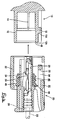
- a resilient sealing ring 40 made from rubber or the like is attached to the circumference of the terminal housing 21 of the female housing 20 at a location immediately to the anterior of the innermost wall 22A of the large hood 22.
- the sealing ring 40 has a rectangular ring shape and is resiliently compressed between an outer circumference of the terminal housing 21 and an inner circumference of an anterior end of the small hood 12, thereby forming a seal.
- Two lips 42 are formed along the entire outer circumference of this sealing ring 40.
- a flange 44 is formed along the entire outer circumference of a posterior end (the right side in Figure 1) of the sealing ring 40, this flange 44 being thicker and slightly higher than the lips 42.
- An outer edge of the flange 44 reaches a location at the approximate centre of the anterior edge 12A of the small hood 12.
- a tapered face 45 is formed at a corner portion of an anterior face side of the outer edge of the flange 44.
- a rounded edge 46 is provided at the opening of the inner circumference side of the anterior edge 12A of the small hood 12.
- the sealing ring 40 is fitted around the terminal housing 21 of the female housing 20, and is pushed in until it makes contact with the innermost wall 22A.
- the female terminal fittings 24, which have ends of electric wires 23 fixed thereto, are pushed from the posterior into the cavities 25. These are retained by the lances 26, and a rubber stopper 28 is fixed to the posterior of each female terminal fitting 24 so as to cover the opening of each cavity 25.
- the retainer (not shown) is fitted to an anterior face of the terminal housing 21, thereby doubly retaining the female terminal fittings 24, and retaining the sealing ring 40 in an anterior direction.
- the female housing 20 is fitted to the male housing 10.
- the anterior end of the locking arm 30 makes contact with the tapered face 15A of the stopping member 15 of the male housing 10, and the anterior end of the locking arm 30 is pushed so as to incline upwards and pass over the stopping member 15.
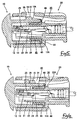
- the anterior edge 12A of the small hood 12 of the male housing 10 approaches the innermost wall 22A of the large hood 22 of the female housing 20. Consequently, as shown in Figure 5, the flange 44 of the sealing ring 40 is resiliently compressed between the anterior edge 12A of the small hood 12 and the innermost wall 22A of the large hood 22.
- the portion of the anterior edge 12A of the small hood 12 provided with the rounded edge 46 pushes the tapered face 45 at the corner of the anterior face of the flange 44, exerting a force to resiliently compress the outer edge of the flange 44 in the direction of thickness thereof and also push the flange 44 in the direction of the outer circumference of the terminal housing 21.
- the female housing 20 is pushed in to a specified position, contacting members of the male and female terminal fittings 13 and 24 make contact and, as shown in Figure 5, the stopped face 35 of the locking arm 30 passes beyond the location of the stopping member 15. Consequently, when the locking arm 30 returns to its original position, the stopping member 15 fits within the groove 34 and is locked. At this juncture, a clearance ordinarily appears between the stopped face 35 of the locking arm 30 and the stopping member 15.
- the female housing 20 is pushed in the posterior direction (to the right in Figure 6) by the returning force of the flange 44 of the sealing ring 40, this returning force being exerted in the direction of thickness thereof. Consequently, the stopped face 35 of the locking arm 30 is pressed resiliently against the stopping member 15.
- the male and female housings 10 and 20 do not vibrate against each other and the male and female terminal fittings 24 and 13 do not rub against each other.
- abrasion of the connecting members of the male and female terminal fittings 124 and 13 is prevented, a good connecting state can be attained, and the connecting pressure is maintained over a long period.
- the tapered face 45 is formed at the corner of the anterior face of the outer edge of the flange 44 of the sealing ring 40, this tapered face 45 pushing the innermost wall 22A of the large hood 22 via the anterior edge 12A of the small hood 12. Consequently, the flange 44 receives a pushing force which pushes it towards the outer circumference of the terminal housing 21, and a suitable force is also exerted o the posterior end of the sealing ring 40, thereby allowing a good seal along the entire width of the sealing ring 40.
- an outer circumference of an anterior edge 12A of the small hood 12 protrudes further to the exterior than the outer edge of the flange 44 of the sealing ring 40.
- This anterior edge 12A protrudes outward from the small hood 12 and makes contact with the innermost wall 22A of the large hood 22. Consequently, further advancement of the small hood 12 is prevented, and the flange 44 is not overly compressed. That is, over-compression of the flange 44 is prevented without increasing the complexity of the configuration.
Landscapes
- Connector Housings Or Holding Contact Members (AREA)
- Details Of Connecting Devices For Male And Female Coupling (AREA)
Abstract
Description
Claims (10)
- An electrical connector comprising a pair of connector housings (10,20) adapted for mutual fitting together in a fitting direction, one of said housings (20) having a resilient locking arm (30) adapted to engage the other of said housings (10) to maintain said housings (10,20) in a fitted state, and a resilient sealing ring (40) being provided between respective circumferential faces of said housings (10,20), charactertised in that said sealing ring (40) has a continuous radially outwardly extending flange (44) adapted to be gripped between opposed faces of said connector housings (10,20) in the fitted condition, one of the sealing ring (40) and connector housings (10,20) having a pushing surface (45,12A) at an angle to said fitting direction and adapted to urge the outer edge of said flange (44) radially inwardly.
- A connector according to claim 1 wherein said pushing surface (45) is provided on said sealing ring (40).
- A connector according to claim 2 wherein said pushing surface (45) faces towards said other housing (10).
- A connector according to claim 3 wherein said pushing surface (45) is flat.
- A connector according to claim3 or claim 4 wherein the outer edge of said flange (44) is aligned with said fitting direction and has a predetermined width, said pushing surface (45) being provided at one side thereof.
- A connector according to any preceding claim wherein said pushing surface (12A) is provided on said other housing.
- A connector according to claim 6 wherein said pushing surface (12A) is arcuate.
- A connector according to any preceding claim wherein said sealing ring (40) includes an axially extending tubular portion insertable in a corresponding aperture of one of said housings (10,20).
- A connector according to claim 8 wherein said tubular portion has peripheral annular sealing projections (42) for engagement in said aperture.
- A connector according to claim 8 or claim 9 wherein said tubular portion has an internal circular recess to locally reduce the wall thickness thereof.
Applications Claiming Priority (2)
| Application Number | Priority Date | Filing Date | Title |
|---|---|---|---|
| JP28322199 | 1999-10-04 | ||
| JP28322199A JP2001110520A (en) | 1999-10-04 | 1999-10-04 | connector |
Publications (3)
| Publication Number | Publication Date |
|---|---|
| EP1091453A2 true EP1091453A2 (en) | 2001-04-11 |
| EP1091453A3 EP1091453A3 (en) | 2002-06-12 |
| EP1091453B1 EP1091453B1 (en) | 2006-01-25 |
Family
ID=17662674
Family Applications (1)
| Application Number | Title | Priority Date | Filing Date |
|---|---|---|---|
| EP00308730A Expired - Lifetime EP1091453B1 (en) | 1999-10-04 | 2000-10-04 | Connector |
Country Status (4)
| Country | Link |
|---|---|
| US (1) | US6368132B1 (en) |
| EP (1) | EP1091453B1 (en) |
| JP (1) | JP2001110520A (en) |
| DE (1) | DE60025681T2 (en) |
Cited By (7)
| Publication number | Priority date | Publication date | Assignee | Title |
|---|---|---|---|---|
| EP1091454A3 (en) * | 1999-10-06 | 2002-07-31 | Sumitomo Wiring Systems, Ltd. | Connector |
| GB2381134A (en) * | 2001-10-22 | 2003-04-23 | Yazaki Corp | Sealed connector |
| FR2874751A1 (en) * | 2004-08-30 | 2006-03-03 | Fci Sa | ELECTRICAL CONNECTOR ADAPTED FOR MITIGATING VIBRATION, IN PARTICULAR FOR A MOTOR VEHICLE INJECTOR |
| EP1710431A1 (en) * | 2005-03-29 | 2006-10-11 | Hirschmann Automotive GmbH | Connector for glow plug of diesel combustion engine having primary and secondary locking means |
| EP1858120A2 (en) | 2006-05-19 | 2007-11-21 | Sanyo Electric Co., Ltd. | Power Source Connection Device and Low-Temperature Showcase including the same |
| EP1988609A3 (en) * | 2007-05-03 | 2009-12-16 | Harting AG | Connector for circuit carrier |
| EP2302741A1 (en) * | 2009-09-25 | 2011-03-30 | Sumitomo Wiring Systems, Ltd. | Split connector and method of assembling it |
Families Citing this family (17)
| Publication number | Priority date | Publication date | Assignee | Title |
|---|---|---|---|---|
| DE20111339U1 (en) * | 2001-07-07 | 2002-11-21 | Robert Bosch Gmbh, 70469 Stuttgart | Wiring harness connector with all-round seal |
| JP3676729B2 (en) * | 2001-12-04 | 2005-07-27 | 住友電装株式会社 | Waterproof rubber stopper |
| JP4214898B2 (en) * | 2003-11-27 | 2009-01-28 | 住友電装株式会社 | Waterproof connector |
| US7201595B1 (en) * | 2006-01-06 | 2007-04-10 | Delphi Technologies, Inc. | Electrical connector body co-molded with cable and peripheral seals |
| JP2008269946A (en) * | 2007-04-20 | 2008-11-06 | Sumitomo Wiring Syst Ltd | Connector |
| US7527515B1 (en) | 2008-07-09 | 2009-05-05 | Metrologic Instruments, Inc. | Cable connector release |
| JP5264604B2 (en) * | 2009-04-17 | 2013-08-14 | 矢崎総業株式会社 | Waterproof connector |
| JP2016046086A (en) * | 2014-08-22 | 2016-04-04 | 株式会社オートネットワーク技術研究所 | Card edge connector |
| JP6176544B2 (en) * | 2015-07-16 | 2017-08-09 | 住友電装株式会社 | connector |
| JP6548036B2 (en) * | 2016-01-29 | 2019-07-24 | 住友電装株式会社 | connector |
| JP7559374B2 (en) * | 2020-06-19 | 2024-10-02 | 株式会社オートネットワーク技術研究所 | Wiring module and elastic water-stopping member |
| JP7559373B2 (en) * | 2020-06-19 | 2024-10-02 | 株式会社オートネットワーク技術研究所 | Wiring module and elastic water-stopping member |
| JP7218072B2 (en) * | 2020-12-16 | 2023-02-06 | 矢崎総業株式会社 | Waterproof connectors and devices with connectors |
| JP2022099946A (en) * | 2020-12-23 | 2022-07-05 | 株式会社オートネットワーク技術研究所 | Wiring module and elastic cutoff member |
| JP7608260B2 (en) * | 2021-04-28 | 2025-01-06 | 日本航空電子工業株式会社 | Electronics |
| JP7639720B2 (en) * | 2022-01-24 | 2025-03-05 | 住友電装株式会社 | connector |
| DE202024103281U1 (en) * | 2024-06-18 | 2024-07-04 | Amphenol Mobile Connector Solutions (Changzhou) Co., Ltd. | Closure structure for a connector, connector and vehicle lamp cable assembly |
Family Cites Families (9)
| Publication number | Priority date | Publication date | Assignee | Title |
|---|---|---|---|---|
| JPH0770337B2 (en) * | 1990-03-23 | 1995-07-31 | 矢崎総業株式会社 | Connector coupling detector |
| JP2542639Y2 (en) * | 1990-11-27 | 1997-07-30 | 住友電装株式会社 | connector |
| JP2784417B2 (en) * | 1993-07-06 | 1998-08-06 | 矢崎総業株式会社 | Inertial lock type waterproof connector |
| JP3299637B2 (en) | 1994-07-27 | 2002-07-08 | 菱星電装株式会社 | connector |
| JP3194698B2 (en) * | 1996-04-26 | 2001-07-30 | 矢崎総業株式会社 | Waterproof connector |
| US6045383A (en) * | 1996-05-17 | 2000-04-04 | The Whitaker Corporation | Sealing member for waterproof connector |
| JP3304039B2 (en) * | 1996-05-17 | 2002-07-22 | タイコエレクトロニクスアンプ株式会社 | Seal member for waterproof connector |
| JP3243786B2 (en) * | 1996-09-04 | 2002-01-07 | 矢崎総業株式会社 | Housing for waterproof connector |
| JP3296298B2 (en) * | 1998-07-23 | 2002-06-24 | 住友電装株式会社 | Waterproof connector |
-
1999
- 1999-10-04 JP JP28322199A patent/JP2001110520A/en active Pending
-
2000
- 2000-10-03 US US09/678,336 patent/US6368132B1/en not_active Expired - Fee Related
- 2000-10-04 DE DE60025681T patent/DE60025681T2/en not_active Expired - Lifetime
- 2000-10-04 EP EP00308730A patent/EP1091453B1/en not_active Expired - Lifetime
Cited By (16)
| Publication number | Priority date | Publication date | Assignee | Title |
|---|---|---|---|---|
| EP1091454A3 (en) * | 1999-10-06 | 2002-07-31 | Sumitomo Wiring Systems, Ltd. | Connector |
| GB2381134A (en) * | 2001-10-22 | 2003-04-23 | Yazaki Corp | Sealed connector |
| US6783381B2 (en) | 2001-10-22 | 2004-08-31 | Yazaki Corporation | Water-proof connector and connector housing therefor |
| DE10247815B4 (en) * | 2001-10-22 | 2005-09-22 | Yazaki Corp. | Waterproof connector and housing for this |
| GB2381134B (en) * | 2001-10-22 | 2006-03-01 | Yazaki Corp | Water-proof connector and connector housing therefor |
| US7785145B2 (en) | 2004-08-30 | 2010-08-31 | Fci | Electrical connector for attenuating vibrations, in particular for the injector of a motor vehicle engine |
| WO2006024485A1 (en) * | 2004-08-30 | 2006-03-09 | Fci | Electrical connector for attenuating vibrations, in particular for the injector of a motor vehicle engine |
| CN100533868C (en) * | 2004-08-30 | 2009-08-26 | Fci公司 | Electrical connector for damping vibrations, in particular for injectors of motor vehicle engines |
| FR2874751A1 (en) * | 2004-08-30 | 2006-03-03 | Fci Sa | ELECTRICAL CONNECTOR ADAPTED FOR MITIGATING VIBRATION, IN PARTICULAR FOR A MOTOR VEHICLE INJECTOR |
| EP1710431A1 (en) * | 2005-03-29 | 2006-10-11 | Hirschmann Automotive GmbH | Connector for glow plug of diesel combustion engine having primary and secondary locking means |
| EP1858120A2 (en) | 2006-05-19 | 2007-11-21 | Sanyo Electric Co., Ltd. | Power Source Connection Device and Low-Temperature Showcase including the same |
| EP1858120A3 (en) * | 2006-05-19 | 2008-12-31 | Sanyo Electric Co., Ltd. | Power Source Connection Device and Low-Temperature Showcase including the same |
| EP1988609A3 (en) * | 2007-05-03 | 2009-12-16 | Harting AG | Connector for circuit carrier |
| EP2302741A1 (en) * | 2009-09-25 | 2011-03-30 | Sumitomo Wiring Systems, Ltd. | Split connector and method of assembling it |
| CN102035101A (en) * | 2009-09-25 | 2011-04-27 | 住友电装株式会社 | Split connector and method of assembling it |
| CN102035101B (en) * | 2009-09-25 | 2013-11-06 | 住友电装株式会社 | Split connector and method of assembling it |
Also Published As
| Publication number | Publication date |
|---|---|
| EP1091453A3 (en) | 2002-06-12 |
| DE60025681T2 (en) | 2006-10-26 |
| JP2001110520A (en) | 2001-04-20 |
| US6368132B1 (en) | 2002-04-09 |
| EP1091453B1 (en) | 2006-01-25 |
| DE60025681D1 (en) | 2006-04-13 |
Similar Documents
| Publication | Publication Date | Title |
|---|---|---|
| EP1091453B1 (en) | Connector | |
| US6558178B2 (en) | Waterproof connector | |
| EP1091454B1 (en) | Connector | |
| EP1160929B1 (en) | A watertight connector, a connector housing and a waterproof member therefor | |
| EP0834961B1 (en) | Lever-type connector | |
| EP1150393B1 (en) | Connector | |
| JPH0430793Y2 (en) | ||
| CA2352541A1 (en) | Electrical plug housing | |
| EP1020958A2 (en) | Connector | |
| JPH0151031B2 (en) | ||
| JPH065150U (en) | Waterproof connector | |
| US5820400A (en) | Half-fitting preventing connector | |
| EP1009065B1 (en) | Waterproof connector | |
| US6793513B2 (en) | Connector with an inertial locking function | |
| EP0923169A1 (en) | Connector containing a short-circuit terminal | |
| US6863551B2 (en) | Connector, set of connectors and method of connecting a connector | |
| JP2005005135A (en) | Connector | |
| US6332804B2 (en) | Connector | |
| JP2001057271A (en) | connector | |
| JPH0557772U (en) | Waterproof connector | |
| JP2004014426A (en) | Connector | |
| WO1997043803A1 (en) | Sealing member for waterproof connector | |
| JP3136909B2 (en) | connector | |
| JP7393296B2 (en) | waterproof connector | |
| JPH077077U (en) | Waterproof connector |
Legal Events
| Date | Code | Title | Description |
|---|---|---|---|
| PUAI | Public reference made under article 153(3) epc to a published international application that has entered the european phase |
Free format text: ORIGINAL CODE: 0009012 |
|
| 17P | Request for examination filed |
Effective date: 20001027 |
|
| AK | Designated contracting states |
Kind code of ref document: A2 Designated state(s): AT BE CH CY DE DK ES FI FR GB GR IE IT LI LU MC NL PT SE |
|
| AX | Request for extension of the european patent |
Free format text: AL;LT;LV;MK;RO;SI |
|
| PUAL | Search report despatched |
Free format text: ORIGINAL CODE: 0009013 |
|
| AK | Designated contracting states |
Kind code of ref document: A3 Designated state(s): AT BE CH CY DE DK ES FI FR GB GR IE IT LI LU MC NL PT SE |
|
| AX | Request for extension of the european patent |
Free format text: AL;LT;LV;MK;RO;SI |
|
| AKX | Designation fees paid |
Designated state(s): DE FR GB IT |
|
| 17Q | First examination report despatched |
Effective date: 20040817 |
|
| GRAP | Despatch of communication of intention to grant a patent |
Free format text: ORIGINAL CODE: EPIDOSNIGR1 |
|
| GRAS | Grant fee paid |
Free format text: ORIGINAL CODE: EPIDOSNIGR3 |
|
| GRAA | (expected) grant |
Free format text: ORIGINAL CODE: 0009210 |
|
| AK | Designated contracting states |
Kind code of ref document: B1 Designated state(s): DE FR GB IT |
|
| PG25 | Lapsed in a contracting state [announced via postgrant information from national office to epo] |
Ref country code: IT Free format text: LAPSE BECAUSE OF FAILURE TO SUBMIT A TRANSLATION OF THE DESCRIPTION OR TO PAY THE FEE WITHIN THE PRESCRIBED TIME-LIMIT;WARNING: LAPSES OF ITALIAN PATENTS WITH EFFECTIVE DATE BEFORE 2007 MAY HAVE OCCURRED AT ANY TIME BEFORE 2007. THE CORRECT EFFECTIVE DATE MAY BE DIFFERENT FROM THE ONE RECORDED. Effective date: 20060125 |
|
| REG | Reference to a national code |
Ref country code: GB Ref legal event code: FG4D |
|
| REF | Corresponds to: |
Ref document number: 60025681 Country of ref document: DE Date of ref document: 20060413 Kind code of ref document: P |
|
| ET | Fr: translation filed | ||
| PLBE | No opposition filed within time limit |
Free format text: ORIGINAL CODE: 0009261 |
|
| STAA | Information on the status of an ep patent application or granted ep patent |
Free format text: STATUS: NO OPPOSITION FILED WITHIN TIME LIMIT |
|
| 26N | No opposition filed |
Effective date: 20061026 |
|
| GBPC | Gb: european patent ceased through non-payment of renewal fee |
Effective date: 20061004 |
|
| PG25 | Lapsed in a contracting state [announced via postgrant information from national office to epo] |
Ref country code: GB Free format text: LAPSE BECAUSE OF NON-PAYMENT OF DUE FEES Effective date: 20061004 |
|
| PGFP | Annual fee paid to national office [announced via postgrant information from national office to epo] |
Ref country code: FR Payment date: 20121018 Year of fee payment: 13 Ref country code: DE Payment date: 20120927 Year of fee payment: 13 |
|
| REG | Reference to a national code |
Ref country code: FR Ref legal event code: ST Effective date: 20140630 |
|
| REG | Reference to a national code |
Ref country code: DE Ref legal event code: R119 Ref document number: 60025681 Country of ref document: DE Effective date: 20140501 |
|
| PG25 | Lapsed in a contracting state [announced via postgrant information from national office to epo] |
Ref country code: FR Free format text: LAPSE BECAUSE OF NON-PAYMENT OF DUE FEES Effective date: 20131031 Ref country code: DE Free format text: LAPSE BECAUSE OF NON-PAYMENT OF DUE FEES Effective date: 20140501 |