EP1091449A2 - Female terminal fitting - Google Patents
Female terminal fitting Download PDFInfo
- Publication number
- EP1091449A2 EP1091449A2 EP00308529A EP00308529A EP1091449A2 EP 1091449 A2 EP1091449 A2 EP 1091449A2 EP 00308529 A EP00308529 A EP 00308529A EP 00308529 A EP00308529 A EP 00308529A EP 1091449 A2 EP1091449 A2 EP 1091449A2
- Authority
- EP
- European Patent Office
- Prior art keywords
- bending
- bending regulating
- fitting
- contacting member
- regulating members
- Prior art date
- Legal status (The legal status is an assumption and is not a legal conclusion. Google has not performed a legal analysis and makes no representation as to the accuracy of the status listed.)
- Granted
Links
Images


Classifications
-
- H—ELECTRICITY
- H01—ELECTRIC ELEMENTS
- H01R—ELECTRICALLY-CONDUCTIVE CONNECTIONS; STRUCTURAL ASSOCIATIONS OF A PLURALITY OF MUTUALLY-INSULATED ELECTRICAL CONNECTING ELEMENTS; COUPLING DEVICES; CURRENT COLLECTORS
- H01R13/00—Details of coupling devices of the kinds covered by groups H01R12/70 or H01R24/00 - H01R33/00
- H01R13/02—Contact members
- H01R13/10—Sockets for co-operation with pins or blades
- H01R13/11—Resilient sockets
- H01R13/113—Resilient sockets co-operating with pins or blades having a rectangular transverse section
Definitions
- the present invention relates to female electrical terminal fitting.
- a female terminal fitting is provided with an angular tubular-shaped fitting member into which a tab of a corresponding male terminal fitting can be inserted, and with a resilient contacting member which protrudes into the fitting member in a bent-over shape from an anterior end of a base wall of this fitting member, this resilient contacting member making resilient contact with the male tab.
- Different female terminal fittings are provided with differing means to prevent the resilient contacting member from bending excessively. An example of one of these means is described in JP-9-35796.
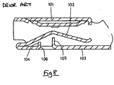
- a female terminal fitting is provided with: an angular tubular-shaped fitting member 101 into which a tab (not shown) of a male terminal fitting can be inserted: a resilient contacting member 102 which extends within the fitting member 101 in the direction of insertion of the tab (the left-right direction in Figure 8) and which is capable of bending resiliently as the tab is inserted into the fitting member 101, thereby making contact with the tab; and two bending regulating members 104 and 105, these bending regulating members 104 and 105 being formed by cutting away a base wall 103 of the fitting member 101.
- both of the bending regulating members 104 and 105 are formed on the base wall 103. Consequently, the area of an opening 106 formed by the cutting away of the bending regulating members 104 and 105 is large, and the base wall 103 is weakened.
- the present invention has taken the above problem into account, and aims to present a female terminal fitting wherein the wall member of the fitting member is not weakened as a result of cutting away bending regulating members therefrom, these bending regulating members preventing the excessive bending of the resilient contacting member.
- a female terminal fitting comprising an elongate box-like body of sheet metal and having an open end adapted to receive a tab of a male terminal fitting in a fitting direction, the body having a resilient contacting member extending in the fitting direction, and in use bending resiliently on contact with a male tab, the female fitting further comprising bending regulating members part sheared from said body and underlying said contacting member to prevent excessive bending thereof, characterized in that said bending regulating members are formed from two or more different walls of said body.
- the contacting member has a pent shape with a contact defined at the apex for making electrical contact with a male terminal tab.
- Two regulating members preferably project towards each other from opposite side walls and present aligned planar faces for contact with the underside of said contacting member.
- the apertures corresponding to these regulating members are preferably arranged to permit viewing of the contacting member therethrough.
- a regulating member preferably protrudes towards the underside of the contacting member at right angles, and a window is preferably formed in a side wall of the body through which this regulating member may be inspected.
- the mouth of the body has inturned portions which narrow the mouth and regulate the width thereof for receiving a male tab.
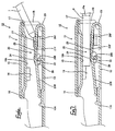
- Figure 1 and Figures 4 to 7 are in an anterior-posterior direction, and the right side is considered to be the anterior.
- the up-down direction is with reference to Figures 1 to 3 and 5 to 7
- the left-right direction is with reference to Figures 2 and 3.
- the insertion direction of a tab T relative to a female terminal fitting 10 refers to the anterior-posterior direction.
- the female terminal fitting 10 of the present embodiment is formed by bending metal sheet which has been punched out in a specified shape.
- the entirety of the female terminal fitting 10 is long and narrow in the anterior-posterior direction.
- Approximately the anterior half thereof forms a fitting member 11, and a posterior half thereof forms an electric wire clamping member 12.
- the fitting member 11 has an angular tubular shape which is open to the anterior and posterior, and is formed from a base wall 13, a pair of side walls 14 rising upwards from left and right side edges of the base wall 13, and a pair of ceiling walls 15 and 16 which extend inwards from upper edges of the two side walls 14 and form a doubled-up upper and lower layer.
- the opening to the anterior side of the fitting member 11 is an insertion hole 17 for allowing the tab T of a male terminal fitting to be inserted.
- Anterior ends of the side walls 14 (left and right side edges of the insertion hole 17) are bent inwards, thereby forming a pair of movement regulating members 18.
- the space between these two movement regulating members 18 is slightly larger than the width of the tab T. Consequently, when the tab T is inserted into the fitting member 11, inner faces of the movement regulating members 18 face both side edges of the tab T, with a small space remaining therebetween (see Figure 4).
- a resilient contacting member 20 is housed within the fitting member 11, this resilient contacting member 20 being bent in a posterior direction from an anterior edge of the base wall 13.
- the resilient contacting member 20 has an angular shape when viewed from the side, an anterior portion thereof forming an inclined member 21 F which is inclined downwards towards the anterior.
- An uppermost edge of this inclined member 21F is a contacting member 22.
- a portion to the posterior of the contacting member 22 is a posterior inclined member 21 R.
- the resilient contacting member 20 can be bent by causing a bent-over member 23 at the anterior end thereof to bend.
- An embossed member 24 is formed by pressing in an upper face of the contacting member 22.
- This embossed member 24 rises upwards in a spherical shape and makes contact with a lower face of the tab T.
- an upper face of the embossed member 24 extends smoothly from the contacting member 22 to a location in the vicinity of an anterior edge of the anterior inclined face 21F, thereby forming a guiding protrusion 25.
- This guiding protrusion 25 is formed by pressing in, and gradually grows narrower in width from the posterior to the anterior.
- a downwardly protruding pressing member 16A is formed by pressing in the lower ceiling wall 16.
- a space Sa is formed between the upper face of the embossed member 24 and a lower face of the pressing member 16A, this space Sa being slightly smaller, by a prescribed degree, than the thickness Ta of the tab T.
- Two bending regulating members 26F and 26R are formed at differing locations within the fitting member 11, a space being provided therebetween in the anterior posterior direction. These bending regulating members 26F and 26R prevent the resilient contacting member 20 from bending excessively.
- the anterior bending regulating members 26F are formed as a pair by cutting away portions of the left and right side walls 14 in a square shape and bending them inwards at approximately right angles at a location below the anterior inclined face 21F of the resilient contacting member 20. These anterior bending regulating members 26F are parallel with the direction of insertion of the tab T. Consequently, when the resilient contacting member 20 is in its natural state, the anterior inclined face 21 F is in an inclined state relative to the anterior bending regulating members 26F. Upper faces of the anterior bending regulating members 26F are located at approximately the same height as an upper end of a bent inner side of the bent-over member 23 of the resilient contacting member 20.
- the anterior inclined face 21 F is approximately parallel with the direction of insertion of the tab T and makes contact with the upper faces of the bending regulating members 26F.
- cut-away holes 27 which open into the side walls 14 (these cut-away holes 27 are formed by cutting away the anterior bending regulating members 26F) allow the bent state (the degree of inclination) of the anterior inclined face 21 F to be verified visually from the exterior of the fitting member 11.
- the posterior bending regulating member 26R is formed from a wall differing from the ones from which the anterior bending regulating members 26F are formed.
- the posterior bending regulating member 26R is formed by cutting away a square portion of the base wall 13 and bending this portion upwards at approximately a right angle at a location directly below the contacting member 22 of the resilient contacting member 20.
- a space Sb which is the space between an upper edge of the posterior bending regulating member 26R and a lower face of the contacting member 22, is larger than the difference in dimension between the space Sa (the space between the embossed member 24 and the pressing member 16A) and the thickness Ta of the tab T (this corresponds to the degree of up down movement of the contacting member 22 when the tab T has been inserted). Consequently, when the tab T has been correctly inserted and the resilient contacting member 20 has bent resiliently (see Figure 5), a space is present between the lower face of the contacting member 22 and the upper edge of the posterior bending regulating member 26R.
- the difference in dimension between the space Sa (the space between the embossed member 24 and the pressing member 16A) and an outer diameter Pa of a probe P for checking conductivity (this difference corresponds to the degree of up down movement of the contacting member 22 when the probe P has been inserted), is the same or smaller than the space Sb between the upper edge of the posterior bending regulating member 26R and the lower face of the contacting member 22. Consequently, when the probe P has been inserted and the resilient contacting member 20 has bent resiliently (see Figure 7), the posterior bending regulating member 26R and the contacting member 22 make contact or an extremely small space remains between them.
- the left and right side walls 14 of the fitting member 11 have window holes 28 for checking the space in an up-down direction between the contacting member 22 of the resilient contacting member 20 and the posterior bending regulating member 26R (that is, for checking the height of the bending regulating member 26R).
- These window holes 28 have a horizontal ellipsoid shape when viewed from the side.
- the window holes 28 are located such that the posterior bending regulating member 26R is located at the approximate centre thereof.
- the posterior bending regulating member 26R protrudes upwards from lower edges of the window holes 28, and the upper edge of the posterior bending regulating member 26R rises to an approximately central portion of the window holes 28.
- the window holes 28 and the resilient contacting member 20 are located relative to one another such that, when the resilient contacting member 20 is in the free state, the lower face of the contacting member 22 and upper edges of the window holes 28 are at approximately the same height.
- the height of the posterior bending regulating member 26R is checked to ensure that it is suitable. This check can be performed by placing the female terminal fitting 10 in a state whereby the interior of the fitting member 11 can be viewed via the window holes 28 of the side walls 14. There are three methods of checking. In the first method, one judges according to the manner in which the upper edge of the bending regulating member 26R is seen through the window holes 28. If the upper edge of the bending regulating member 26R cannot be seen through the window holes 28, this means that the bending regulating member 26R is too low and the resilient contacting member 20 may bend excessively. The article is accordingly judged defective.
- the bending regulating member 26R is higher than the opening of the window holes 28, with the bending regulating member 26R appearing to divide the window holes 28 into two sections, this means that the bending regulating member 26R is too high and it may impede the insertion of the tab T of the male terminal fitting or the insertion of the conductivity checking probe P.
- the article is accordingly judged defective. After the upper edge of the bending regulating member 26R is at a height whereby it fits suitably within the opening range of the window holes 28, the following check can be performed.
- the second check is performed using the tab T.
- the contacting member 22 moves downwards as the resilient contacting member 20 bends resiliently, this allowing visual verification through the window holes 28.
- the contacting member 22 does not make contact with the posterior bending regulating member 26R (see Figure 5)
- the height of the bending regulating member 26R is suitable and does not impede contact with the tab T. Consequently, the article is judged non-defective. If the lower face of the contacting member 22 makes contact with the upper edge of the bending regulating member 26R when the tab T is inserted, the bending regulating member 26R is too high and may impede contact with the tab T. Consequently, the article is judged defective.
- the probe P can be used to perform a third check on height. This check may take the place of the second check, or may be performed before or after it.
- the contacting member 22 moves downwards as the resilient contacting member 20 bends resiliently, this movement allowing visual verification through the window holes 28.
- the height of the bending regulating member 26R is suitable and does not impede the conductivity check of the probe P. Consequently, the article is judged non-defective.
- the resilient contacting member 20 remains within its range of bending. If the bending regulating member 26R is too high, the contacting member 22 makes contact with the upper edge of the bending regulating member 26R while the probe P is being inserted, preventing further bending of the resilient contacting member 20 and further insertion of the probe P. Consequently, the article is not suitable for the conductivity check and is judged defective.
- the tip of the tab T does not slide over the anterior inclined face 21F but strikes against it; this pushes the anterior inclined face 21 F downwards and to the posterior. Then, within the range of resilient bending of the resilient contacting member 20, the anterior inclined face 21F makes contact with the upper faces of the anterior bending regulating members 26F and the contacting member 22 makes contact with the upper edge of the posterior bending regulating member 26R, thereby preventing further bending of the resilient contacting member 20. Consequently, the resilient contacting member 20 can reliably be prevented from exceeding its range of bending.
- the tip of the tab T makes localized contact at a large angle with the anterior inclined face 21F.
- the position where the tab T makes contact is distant from the location which receives the bending regulating members. Consequently, there is the danger that the anterior inclined face 21F may change shape and become concave.
- the anterior inclined face 21 F makes contact with the bending regulating members 26F along a wide range of this face along the anterior and posterior directions.
- the contacting position of the tab T is removed from the range which receives the bending regulating members 26F, and the anterior inclined face 21 F is thereby prevented from changing shape.
- the fact that the retaining face is wide means that the resisting force (rigidity) with respect to the contacting force of the tab T is large. Consequently. the anterior inclined face 21 F is very reliably prevented from changing shape.
- the entirety of the resilient contacting member 20 is also reliably prevented from being excessively bent.
- the bending regulating members 26F and 26R are provided at two locations, an anterior location and a posterior location relative to the length-wise direction of the resilient contacting member 20. Consequently, the resilient contacting member 20 can reliably be prevented from bending excessively. Furthermore, the two bending regulating members 26F and 26R are formed on mutually differing walls (the side walls 14 and the base wall 13) of the fitting member 11. Consequently, compared to the case where the two bending regulating members 26F and 26R are formed on a single wall, the opening area formed by cutting away the bending regulating members is smaller on each wall, and consequently the walls are stronger.
- the tab T is inserted into the fitting member 11 and the space between the bending regulating member 26R and the contacting member 22 when the resilient contacting member 20 has bent resiliently is checked (that is, the height of the posterior bending regulating member 26R is checked).
- the window holes 28 are provided to allow this checking to be performed visually. This simplifies the checking operation.
- the movement regulating members 18 are formed on the opening edge of the insertion hole 17 of the fitting member 11 by bending the anterior ends of the side walls 14 inwards. These movement regulating members 18 thereby oppose the side edges of the tab T.
- the interior dimension of the fitting member 11 relative to the width-wise direction of the tab T becomes smaller, and the clearance between the side walls 14 of the fitting member 11 and the side edges of the tab T is smaller. Consequently, the movement of the tab T in a width-wise direction is regulated.
- the present invention is not limited to the embodiments described above with the aid of figures. For example, the possibilities described below also lie within the technical range of the present invention. In addition, the present invention may be embodied in various other ways without deviating from the scope thereof.
Landscapes
- Details Of Connecting Devices For Male And Female Coupling (AREA)
- Coupling Device And Connection With Printed Circuit (AREA)
Abstract
Description
Claims (10)
- A female terminal fitting (16) comprising an elongate box-like body (11) of sheet metal and having an open end adapted to receive a tab of a male terminal fitting in a fitting direction, the body having a resilient contacting member (20) extending in the fitting direction, and in use bending resiliently on contact with a male tab, the female fitting (10) further comprising bending regulating members (26F,26R) part sheared from said body (11) and underlying said contacting member (20) to prevent excessive bending thereof, characterized in that said bending regulating members (26F,26R) are formed from two or more different walls (13,14) of said body (11).
- A fitting according to claim 1 wherein said resilient contacting member (20) is a cantilever having a root (23) connected to said body (11), and a contact (24) for making electrical contact with a male tab, said contacting member (20) having a proximal portion (21F) inclining in the free condition from said root (23) to said contact (24) with respect to said fitting direction, and one of said bending regulating members is a proximal bending regulating member (26F) having a planar face for contact with said proximal portion (21F).
- A fitting according to claim 2 wherein said planar face extends in said fitting direction.
- A fitting according to claim 2 or claim 3 wherein said proximal bending regulating member (26F) has an associated aperture (27) in the wall of said body (11), said aperture (27) being on the opposite side of said proximal bending regulating member (26F) to said contacting member (20).
- A fitting according to any of claims 2-4 wherein proximal bending regulating members (26F) are formed from opposite side walls (14) of said body (11) each having a planar face for contact with said proximal portion (21F).
- A fitting according to any preceding claim wherein a distal bending regulating member (26R) extends towards the underside of said contacting member (20), substantially at right angles thereto, and said body (11) includes a window (28) in a side wall thereof through which said distal bending regulating member (26R) may be observed.
- A fitting according to claim 6 wherein said window (28) lies wholly to the underside of said contacting member (20) when in the free condition.
- A fitting according to claim 1 wherein said body has a base (13), two sides (14) and a top (15,16), said contacting member (20) being a cantilever extending from said base (13) and having a free end (21R) angled towards said base (13) in the fitting direction, said base (13) having an indent (13A) providing a bearing surface for said free end (21R) in the free condition of said contacting member (20).
- A fitting according to claim 8 wherein said top (15,16) has a protrusion (16A) extending in the fitting direction and defining with said contacting member (20) a contacting space (Sa) for a male tab.
- A fitting according to any preceding claim wherein said open end has inturned wall portions (18) on opposite sides, said wall portions (18) defining therebetween a regulating space for a male tab (T).
Applications Claiming Priority (2)
| Application Number | Priority Date | Filing Date | Title |
|---|---|---|---|
| JP28862499A JP3473521B2 (en) | 1999-10-08 | 1999-10-08 | Female terminal fitting |
| JP28862499 | 1999-10-08 |
Publications (3)
| Publication Number | Publication Date |
|---|---|
| EP1091449A2 true EP1091449A2 (en) | 2001-04-11 |
| EP1091449A3 EP1091449A3 (en) | 2003-04-09 |
| EP1091449B1 EP1091449B1 (en) | 2004-09-22 |
Family
ID=17732603
Family Applications (1)
| Application Number | Title | Priority Date | Filing Date |
|---|---|---|---|
| EP00308529A Expired - Lifetime EP1091449B1 (en) | 1999-10-08 | 2000-09-28 | Female terminal fitting |
Country Status (4)
| Country | Link |
|---|---|
| US (1) | US6478636B1 (en) |
| EP (1) | EP1091449B1 (en) |
| JP (1) | JP3473521B2 (en) |
| DE (1) | DE60014000T2 (en) |
Cited By (5)
| Publication number | Priority date | Publication date | Assignee | Title |
|---|---|---|---|---|
| WO2007097879A3 (en) * | 2006-02-21 | 2008-06-12 | Fci Americas Technology Inc | Electrical connectors having power contacts with alignment features |
| DE102007049055B3 (en) * | 2007-10-11 | 2009-03-26 | Tyco Electronics Amp Gmbh | Vibration damping contact element |
| EP2309603A1 (en) * | 2009-10-09 | 2011-04-13 | Sumitomo Wiring Systems, Ltd. | Female terminal fitting and method of connecting it |
| US9831605B2 (en) | 2012-04-13 | 2017-11-28 | Fci Americas Technology Llc | High speed electrical connector |
| US10720721B2 (en) | 2009-03-19 | 2020-07-21 | Fci Usa Llc | Electrical connector having ribbed ground plate |
Families Citing this family (51)
| Publication number | Priority date | Publication date | Assignee | Title |
|---|---|---|---|---|
| JP3875526B2 (en) * | 2001-08-10 | 2007-01-31 | 矢崎総業株式会社 | Terminal spring structure |
| US20040147169A1 (en) | 2003-01-28 | 2004-07-29 | Allison Jeffrey W. | Power connector with safety feature |
| JP2005166594A (en) * | 2003-12-05 | 2005-06-23 | Auto Network Gijutsu Kenkyusho:Kk | Female terminal structure |
| KR20060118567A (en) | 2003-12-31 | 2006-11-23 | 에프씨아이 | Power contacts and connectors containing them |
| JP3976008B2 (en) * | 2004-01-07 | 2007-09-12 | 住友電装株式会社 | Terminal fitting |
| JP2006107934A (en) * | 2004-10-06 | 2006-04-20 | Jst Mfg Co Ltd | Female contact |
| US7476108B2 (en) | 2004-12-22 | 2009-01-13 | Fci Americas Technology, Inc. | Electrical power connectors with cooling features |
| JP4259472B2 (en) * | 2005-02-02 | 2009-04-30 | 住友電装株式会社 | Terminal fitting |
| US7303427B2 (en) | 2005-04-05 | 2007-12-04 | Fci Americas Technology, Inc. | Electrical connector with air-circulation features |
| JP4548190B2 (en) * | 2005-04-13 | 2010-09-22 | 住友電装株式会社 | Terminal fitting |
| JP2007149504A (en) * | 2005-11-28 | 2007-06-14 | Yazaki Corp | Female terminals and connectors |
| US7425145B2 (en) | 2006-05-26 | 2008-09-16 | Fci Americas Technology, Inc. | Connectors and contacts for transmitting electrical power |
| US7726982B2 (en) | 2006-06-15 | 2010-06-01 | Fci Americas Technology, Inc. | Electrical connectors with air-circulation features |
| US7641500B2 (en) | 2007-04-04 | 2010-01-05 | Fci Americas Technology, Inc. | Power cable connector system |
| JP4858293B2 (en) * | 2007-05-08 | 2012-01-18 | 住友電装株式会社 | Female terminal bracket |
| US7503813B1 (en) | 2007-05-17 | 2009-03-17 | Yazaki North America, Inc. | Electrical terminal with contoured contact element |
| US7905731B2 (en) | 2007-05-21 | 2011-03-15 | Fci Americas Technology, Inc. | Electrical connector with stress-distribution features |
| US8062051B2 (en) | 2008-07-29 | 2011-11-22 | Fci Americas Technology Llc | Electrical communication system having latching and strain relief features |
| US8043131B2 (en) | 2008-09-19 | 2011-10-25 | Fci Americas Technology Llc | Electrical cable contact |
| USD610548S1 (en) | 2009-01-16 | 2010-02-23 | Fci Americas Technology, Inc. | Right-angle electrical connector |
| USD606496S1 (en) | 2009-01-16 | 2009-12-22 | Fci Americas Technology, Inc. | Right-angle electrical connector |
| USD664096S1 (en) | 2009-01-16 | 2012-07-24 | Fci Americas Technology Llc | Vertical electrical connector |
| USD608293S1 (en) | 2009-01-16 | 2010-01-19 | Fci Americas Technology, Inc. | Vertical electrical connector |
| USD640637S1 (en) | 2009-01-16 | 2011-06-28 | Fci Americas Technology Llc | Vertical electrical connector |
| USD606497S1 (en) | 2009-01-16 | 2009-12-22 | Fci Americas Technology, Inc. | Vertical electrical connector |
| US8323049B2 (en) | 2009-01-30 | 2012-12-04 | Fci Americas Technology Llc | Electrical connector having power contacts |
| USD619099S1 (en) | 2009-01-30 | 2010-07-06 | Fci Americas Technology, Inc. | Electrical connector |
| USD618181S1 (en) | 2009-04-03 | 2010-06-22 | Fci Americas Technology, Inc. | Asymmetrical electrical connector |
| USD618180S1 (en) | 2009-04-03 | 2010-06-22 | Fci Americas Technology, Inc. | Asymmetrical electrical connector |
| JP5482556B2 (en) | 2010-08-06 | 2014-05-07 | 住友電装株式会社 | Terminal fitting |
| EP2624034A1 (en) | 2012-01-31 | 2013-08-07 | Fci | Dismountable optical coupling device |
| US8944831B2 (en) | 2012-04-13 | 2015-02-03 | Fci Americas Technology Llc | Electrical connector having ribbed ground plate with engagement members |
| USD718253S1 (en) | 2012-04-13 | 2014-11-25 | Fci Americas Technology Llc | Electrical cable connector |
| USD727852S1 (en) | 2012-04-13 | 2015-04-28 | Fci Americas Technology Llc | Ground shield for a right angle electrical connector |
| USD727268S1 (en) | 2012-04-13 | 2015-04-21 | Fci Americas Technology Llc | Vertical electrical connector |
| US8974256B2 (en) * | 2012-04-26 | 2015-03-10 | Sumitomo Wiring Systems, Ltd. | Terminal fitting and production method therefor |
| USD751507S1 (en) | 2012-07-11 | 2016-03-15 | Fci Americas Technology Llc | Electrical connector |
| US9543703B2 (en) | 2012-07-11 | 2017-01-10 | Fci Americas Technology Llc | Electrical connector with reduced stack height |
| CN202772303U (en) * | 2012-09-04 | 2013-03-06 | 泰科电子(上海)有限公司 | Electrical connector and electrical connector assembly |
| USD745852S1 (en) | 2013-01-25 | 2015-12-22 | Fci Americas Technology Llc | Electrical connector |
| JP2014160545A (en) * | 2013-02-19 | 2014-09-04 | Sumitomo Wiring Syst Ltd | Female terminal metal fitting |
| JP2014170709A (en) * | 2013-03-05 | 2014-09-18 | Sumitomo Wiring Syst Ltd | Female terminal fitting |
| USD720698S1 (en) | 2013-03-15 | 2015-01-06 | Fci Americas Technology Llc | Electrical cable connector |
| US9118130B1 (en) * | 2014-02-06 | 2015-08-25 | Delphi Technologies, Inc. | Low insertion force terminal |
| JP6269309B2 (en) * | 2014-05-14 | 2018-01-31 | 住友電装株式会社 | Female terminal |
| JP6607141B2 (en) * | 2016-05-12 | 2019-11-20 | 住友電装株式会社 | Terminal |
| KR101827118B1 (en) * | 2016-05-23 | 2018-02-07 | 엘에스산전 주식회사 | Circuit breaker |
| JP2020042914A (en) * | 2018-09-06 | 2020-03-19 | 矢崎総業株式会社 | Terminal fitting |
| JP7005117B2 (en) * | 2019-05-29 | 2022-01-21 | 矢崎総業株式会社 | Wires with terminals and wire harnesses |
| JP7810985B2 (en) * | 2020-07-17 | 2026-02-04 | 日本圧着端子製造株式会社 | contact |
| JP7626021B2 (en) * | 2021-10-25 | 2025-02-04 | 住友電装株式会社 | Terminals and Connectors |
Family Cites Families (11)
| Publication number | Priority date | Publication date | Assignee | Title |
|---|---|---|---|---|
| US4560231A (en) * | 1983-03-10 | 1985-12-24 | Elco International K.K. | Electrical connector |
| JPH0660931A (en) * | 1992-08-04 | 1994-03-04 | Fujikura Ltd | Electrical connector |
| JP2603930Y2 (en) * | 1993-09-01 | 2000-04-04 | 矢崎総業株式会社 | Female terminal fitting |
| FR2711853B1 (en) * | 1993-10-26 | 1995-12-01 | Cinch Connecteurs Sa | Female electrical contact member. |
| JP2596910Y2 (en) * | 1993-11-30 | 1999-06-28 | 日本エー・エム・ピー株式会社 | Female contact |
| JP3533536B2 (en) * | 1994-07-11 | 2004-05-31 | 住友電装株式会社 | Female terminal fitting |
| US5630738A (en) * | 1994-07-21 | 1997-05-20 | Sumitomo Wiring Systems, Ltd. | Female terminal, metal fixture |
| US5791945A (en) * | 1995-04-13 | 1998-08-11 | The Whitaker Corporation | High force contact |
| JPH0935796A (en) * | 1995-07-24 | 1997-02-07 | Yazaki Corp | Female terminal |
| JP3258534B2 (en) * | 1995-07-28 | 2002-02-18 | タイコエレクトロニクスアンプ株式会社 | Female contact |
| JP3494347B2 (en) * | 1998-03-06 | 2004-02-09 | 矢崎総業株式会社 | Terminal sag prevention structure |
-
1999
- 1999-10-08 JP JP28862499A patent/JP3473521B2/en not_active Expired - Lifetime
-
2000
- 2000-09-28 EP EP00308529A patent/EP1091449B1/en not_active Expired - Lifetime
- 2000-09-28 DE DE60014000T patent/DE60014000T2/en not_active Expired - Lifetime
- 2000-10-03 US US09/678,306 patent/US6478636B1/en not_active Expired - Lifetime
Cited By (6)
| Publication number | Priority date | Publication date | Assignee | Title |
|---|---|---|---|---|
| WO2007097879A3 (en) * | 2006-02-21 | 2008-06-12 | Fci Americas Technology Inc | Electrical connectors having power contacts with alignment features |
| DE102007049055B3 (en) * | 2007-10-11 | 2009-03-26 | Tyco Electronics Amp Gmbh | Vibration damping contact element |
| US7988505B2 (en) | 2007-10-11 | 2011-08-02 | Tyco Electronics Amp Gmbh | Vibration-damping contact element |
| US10720721B2 (en) | 2009-03-19 | 2020-07-21 | Fci Usa Llc | Electrical connector having ribbed ground plate |
| EP2309603A1 (en) * | 2009-10-09 | 2011-04-13 | Sumitomo Wiring Systems, Ltd. | Female terminal fitting and method of connecting it |
| US9831605B2 (en) | 2012-04-13 | 2017-11-28 | Fci Americas Technology Llc | High speed electrical connector |
Also Published As
| Publication number | Publication date |
|---|---|
| US6478636B1 (en) | 2002-11-12 |
| EP1091449A3 (en) | 2003-04-09 |
| JP3473521B2 (en) | 2003-12-08 |
| EP1091449B1 (en) | 2004-09-22 |
| DE60014000T2 (en) | 2005-11-10 |
| DE60014000D1 (en) | 2004-10-28 |
| JP2001110496A (en) | 2001-04-20 |
Similar Documents
| Publication | Publication Date | Title |
|---|---|---|
| EP1091449B1 (en) | Female terminal fitting | |
| US5593328A (en) | Female terminal fitting for connector | |
| EP0618644B1 (en) | Electrical terminal | |
| EP2244334B1 (en) | Terminal fitting and method of forming it | |
| US5681190A (en) | Torsional blade receptacle | |
| EP1890363B1 (en) | A female terminal fitting | |
| US20080070452A1 (en) | Female Contact | |
| EP1107376A2 (en) | Female connection terminal | |
| EP0935827B1 (en) | Contact with latch for contact retention and housing therefor | |
| EP1094550A2 (en) | Electrical terminal with multi-directional installation and self-tightening latch mechanism | |
| EP2485334A1 (en) | Multi-contact terminal fitting | |
| WO2012173961A1 (en) | Receptacle contact | |
| US20010051471A1 (en) | Female terminal fitting | |
| EP3482464B1 (en) | Terminal with reduced normal force | |
| CN1815816B (en) | A terminal fitting, connector provided therewith and method of forming a terminal fitting | |
| EP0178102A2 (en) | Electrical terminals and connector assemblies | |
| EP1146605B1 (en) | Connector | |
| US10381764B2 (en) | Terminal | |
| US4904202A (en) | Spring locking device for connector | |
| US5529511A (en) | Electrical contact | |
| US7204728B2 (en) | Terminal fitting and a connector provided therewith | |
| JPH0471315B2 (en) | ||
| EP1168518A2 (en) | Connector | |
| JP2911020B2 (en) | Electrical connection terminal | |
| US6283803B1 (en) | Electrical contact |
Legal Events
| Date | Code | Title | Description |
|---|---|---|---|
| PUAI | Public reference made under article 153(3) epc to a published international application that has entered the european phase |
Free format text: ORIGINAL CODE: 0009012 |
|
| 17P | Request for examination filed |
Effective date: 20001020 |
|
| AK | Designated contracting states |
Kind code of ref document: A2 Designated state(s): AT BE CH CY DE DK ES FI FR GB GR IE IT LI LU MC NL PT SE |
|
| AX | Request for extension of the european patent |
Free format text: AL;LT;LV;MK;RO;SI |
|
| PUAL | Search report despatched |
Free format text: ORIGINAL CODE: 0009013 |
|
| AK | Designated contracting states |
Designated state(s): AT BE CH CY DE DK ES FI FR GB GR IE IT LI LU MC NL PT SE Kind code of ref document: A3 Designated state(s): AT BE CH CY DE DK ES FI FR GB GR IE IT LI LU MC NL PT SE |
|
| AX | Request for extension of the european patent |
Extension state: AL LT LV MK RO SI |
|
| 17Q | First examination report despatched |
Effective date: 20030627 |
|
| AKX | Designation fees paid |
Designated state(s): DE FR GB IT |
|
| GRAP | Despatch of communication of intention to grant a patent |
Free format text: ORIGINAL CODE: EPIDOSNIGR1 |
|
| GRAS | Grant fee paid |
Free format text: ORIGINAL CODE: EPIDOSNIGR3 |
|
| GRAA | (expected) grant |
Free format text: ORIGINAL CODE: 0009210 |
|
| AK | Designated contracting states |
Kind code of ref document: B1 Designated state(s): DE FR GB IT |
|
| PG25 | Lapsed in a contracting state [announced via postgrant information from national office to epo] |
Ref country code: IT Free format text: LAPSE BECAUSE OF FAILURE TO SUBMIT A TRANSLATION OF THE DESCRIPTION OR TO PAY THE FEE WITHIN THE PRESCRIBED TIME-LIMIT;WARNING: LAPSES OF ITALIAN PATENTS WITH EFFECTIVE DATE BEFORE 2007 MAY HAVE OCCURRED AT ANY TIME BEFORE 2007. THE CORRECT EFFECTIVE DATE MAY BE DIFFERENT FROM THE ONE RECORDED. Effective date: 20040922 Ref country code: FR Free format text: LAPSE BECAUSE OF FAILURE TO SUBMIT A TRANSLATION OF THE DESCRIPTION OR TO PAY THE FEE WITHIN THE PRESCRIBED TIME-LIMIT Effective date: 20040922 |
|
| REG | Reference to a national code |
Ref country code: GB Ref legal event code: FG4D |
|
| REG | Reference to a national code |
Ref country code: IE Ref legal event code: FG4D |
|
| REF | Corresponds to: |
Ref document number: 60014000 Country of ref document: DE Date of ref document: 20041028 Kind code of ref document: P |
|
| PG25 | Lapsed in a contracting state [announced via postgrant information from national office to epo] |
Ref country code: GB Free format text: LAPSE BECAUSE OF NON-PAYMENT OF DUE FEES Effective date: 20041222 |
|
| REG | Reference to a national code |
Ref country code: IE Ref legal event code: MM4A |
|
| PLBE | No opposition filed within time limit |
Free format text: ORIGINAL CODE: 0009261 |
|
| STAA | Information on the status of an ep patent application or granted ep patent |
Free format text: STATUS: NO OPPOSITION FILED WITHIN TIME LIMIT |
|
| GBPC | Gb: european patent ceased through non-payment of renewal fee |
Effective date: 20041222 |
|
| 26N | No opposition filed |
Effective date: 20050623 |
|
| EN | Fr: translation not filed | ||
| REG | Reference to a national code |
Ref country code: DE Ref legal event code: R084 Ref document number: 60014000 Country of ref document: DE |
|
| PGFP | Annual fee paid to national office [announced via postgrant information from national office to epo] |
Ref country code: DE Payment date: 20190917 Year of fee payment: 20 |
|
| REG | Reference to a national code |
Ref country code: DE Ref legal event code: R071 Ref document number: 60014000 Country of ref document: DE |