EP1091377A2 - Vacuum exhaust element of vacuum switch - Google Patents
Vacuum exhaust element of vacuum switch Download PDFInfo
- Publication number
- EP1091377A2 EP1091377A2 EP00121794A EP00121794A EP1091377A2 EP 1091377 A2 EP1091377 A2 EP 1091377A2 EP 00121794 A EP00121794 A EP 00121794A EP 00121794 A EP00121794 A EP 00121794A EP 1091377 A2 EP1091377 A2 EP 1091377A2
- Authority
- EP
- European Patent Office
- Prior art keywords
- vacuum
- exhaust element
- projection portion
- vacuum exhaust
- electrode
- Prior art date
- Legal status (The legal status is an assumption and is not a legal conclusion. Google has not performed a legal analysis and makes no representation as to the accuracy of the status listed.)
- Granted
Links
Images




Classifications
-
- H—ELECTRICITY
- H01—ELECTRIC ELEMENTS
- H01H—ELECTRIC SWITCHES; RELAYS; SELECTORS; EMERGENCY PROTECTIVE DEVICES
- H01H33/00—High-tension or heavy-current switches with arc-extinguishing or arc-preventing means
- H01H33/60—Switches wherein the means for extinguishing or preventing the arc do not include separate means for obtaining or increasing flow of arc-extinguishing fluid
- H01H33/66—Vacuum switches
- H01H33/668—Means for obtaining or monitoring the vacuum
-
- H—ELECTRICITY
- H01—ELECTRIC ELEMENTS
- H01H—ELECTRIC SWITCHES; RELAYS; SELECTORS; EMERGENCY PROTECTIVE DEVICES
- H01H33/00—High-tension or heavy-current switches with arc-extinguishing or arc-preventing means
- H01H33/60—Switches wherein the means for extinguishing or preventing the arc do not include separate means for obtaining or increasing flow of arc-extinguishing fluid
- H01H33/66—Vacuum switches
- H01H33/668—Means for obtaining or monitoring the vacuum
- H01H33/6683—Means for obtaining or monitoring the vacuum by gettering
Definitions
- the present invention relates to a vacuum switch with a vacuum exhaust element.
- the interruption performance of a vacuum valve drops down suddenly at 10 -4 Torr or below.
- a change in vacuum pressure is caused not only by the leakage of vacuum due to generation of cracking but also by the release of gas molecules adsorbed in metal or insulating material, further by the transmission of atmospheric gas, and so on.
- a vacuum vessel becomes larger in size as a higher rated voltage is requested of such a vacuum valve, the release of adsorbed gas or the transmission of atmospheric gas cannot be bypassed.
- a vacuum exhaust element is attached so as to project from a vacuum vessel to the outside.
- the vacuum exhaust element is provided in portion connected to the bus. Therefore, there is a problem that an insulating transformer is required for a power source so that the whole size of the vacuum switch with the insulating transformer becomes larger.
- a vacuum exhaust element comprising: a projection portion projecting to the outside from a part of the grounded vacuum vessel; a magnetic field generator disposed outside the projection portion; and a power source circuit connected with an electrode and a getter which are provided in the projection portion.
- a vacuum exhaust element has a projection portion projecting from a part of the grounded vacuum vessel in the same direction as one of rods connected to the electrodes respectively; a magnetic field generator disposed outside the projection portion; and a power source circuit connected with an electrode and a getter which are provided in the projection portion.
- a vacuum exhaust element has a projection portion projecting from a part of the grounded vacuum vessel in the same direction as one of rods connected to the electrodes respectively; a magnetic field generator disposed outside the projection portion; and a power source circuit connected with an electrode and a getter which are provided in the projection portion.
- the vacuum exhaust element is made shorter than the one rod.
- the vacuum exhaust element may be disposed under the one rod in opposition to each other.
- the vacuum vessel and the power source circuit may be connected to the ground.
- an insulator may be put between the grounded vacuum vessel and the projection portion.
- the electrode provided in the projection portion may be constituted by a high-voltage-side electrode and a low-voltage-side electrode through an electric discharge gap.
- a getter layer may be provided in an inner wall surface of the projection portion.
- an insulation resistance meter may be connected to the power source circuit.
- Fig. 1 is an overall configuration view of a vacuum switch
- Fig. 2 is a detail sectional view of a vacuum valve 1.
- FIG. 1 shows a switchgear for operating the vacuum valve 1 by an operating mechanism 25.
- the operating mechanism 25 is chiefly constituted by an interrupting spring 21. Released by a trip mechanism provided with a stopper 23 individually, the interrupting spring 21 generates driving force which is transmitted to an insulating rod 9 through a shaft 22. As a result, the insulating rod 9 is driven up/down so that a fixed electrode 5 and a movable electrode 6 are closed/opened.
- a pair of bushings 3 and 4 are provided around a vacuum vessel 2 which is connected to the ground E to thereby form the vacuum valve 1, as shown in Fig. 2.
- the two bushings 3 and 4 are disposed perpendicularly to each other on the vacuum vessel 2.
- the movable electrode 6 is made to abut against or depart from the fixed electrode 5 disposed inside the vacuum vessel 2 so as to perform switching on or off.
- a rod 5A is fixed to the bushing 3 and connected to the fixed electrode 5.
- a rod 6A is fixed to the bushing 4 and connected to the fixed electrode 6 through a flexible conductor 8. That is, for the fixed and movable electrodes 5 and 6, the rods 5A and 6A extend from the inside of the vacuum vessel 2 to the outside perpendicularly to each other so as to penetrate the bushings 3 and 4, respectively.
- an electric current flows in the patch from the rod 5A to the rod 6A through the fixed electrode 5, the movable electrode 6 and the flexible conductor 8.
- the movable electrode 6 and the insulating rod 9 are fixed to the vacuum vessel 2 through bellows 10.
- the forward end of the insulating rod 9 is mechanically coupled with the operating mechanism 25.
- An arc shield 11 interrupts electric short-circuit between the vacuum vessel 2 and the rod 5A due to arc produced at the time of switching-off to thereby prevent a ground fault.
- a vacuum exhaust element 30 is attached to the side surface of the vacuum vessel 2 in the same direction as the bushing 4.
- the detailed structure of the vacuum exhaust element 30 is shown in Fig. 3, and is explained with reference to Fig. 3.
- the vacuum exhaust element 30 is constituted by a projection portion 33, an electrode 32, a power source circuit 34, a getter 38, and a magnetic field generator 36A.
- the projection portion 33 is made of a metal vessel and formed on a part of the side surface of the vacuum vessel 2 so as to project in the same direction as the bushing 4.
- the electrode 32 is provided in the projection portion 33 so as to communicate with the outside and inside of the vacuum vessel 2.
- the power source circuit 34 is connected to the electrode 32.
- the getter 38 is provided in the projection portion 33 correspondingly to the electrode 32 so as to have the same potential as the projection portion 33.
- the magnetic field generator 36A has an iron plate 35 disposed around the projection portion 33, and a coil 36 wound around the iron core. The iron plates 35 prevent the magnetic flux produced by coil current from entering the vacuum vessel.
- An insulating portion 31 is provided between the electrode 32 and the projection portion 33 so as to electrically insulate them from each other. Such an insulating portion may be provided at a part of the electrode 32.
- a DC power source 43 is connected to the power source circuit 34.
- the DC power source 43 used in Fig. 3 may be replaced by an AC positive pulse generating circuit.
- the coil 36 may be replaced by a ring-like permanent magnet 37 as shown in Fig. 4. Then, the polarities N and S of the permanent magnet may be replaced by each other.
- the power source circuit 34 is connected to the ground E.
- a DC voltage is applied to the power source circuit 34. Electrons e discharged from the inner wall of the projection portion 33 is affected by Lorentz force due to an electric field E and a magnetic field B applied by the coil 36. Thus, the electrons e circulate around the electrode 32. The circulating electrons e ionize residual gas in the vessel by collision therewith. Thus, the residual gas is made into positive ions Z, which are captured by the getter 38 at the same potential as the projection portion 33.
- the positive ions Z are attracted at a high speed by the getter 38 at the same potential as the projection portion 38. Therefore, in comparison with the case where a getter is provided simply, it is possible to enhance the exhaust efficiency and it is difficult to accelerate deterioration in vacuum. Thus, the reliability against deterioration in vacuum increases. As a result, it is possible to provide a vacuum switch which is high in safety.
- the voltage application may be carried out all the time or only at the time of maintenance/inspection. In the latter case, the vacuum pressure changes as shown in Fig. 5. In Fig. 5, the time of "voltage application" means the time of "maintenance/inspection".
- the vacuum vessel 2 and the power source circuit 34 are connected to the ground E, so that their potentials are always zero. Accordingly, the vacuum exhaust element 30 does not need a withstand voltage in which a higher voltage than in a conventional vacuum exhaust element is taken into account. That is, it will go well if the vacuum exhaust element 30 has an ordinary withstand voltage. Accordingly, the vacuum exhaust element 30 according to the present invention can be miniaturized in comparison with the conventional vacuum exhaust element. In addition, it is safe for a worker to touch the vacuum vessel 2 and the vacuum exhaust element 30 when the worker carries out maintenance/inspection.
- the vacuum exhaust element 30 is configured as follows. That is, the rods 5A and 6A connected to the both electrodes extend to the outside from the vacuum vessel perpendicularly to each other.
- the projection portion 33 is provided on a part of the vacuum vessel so as to project in the same direction as the rod 6A.
- the magnetic field generator 35 is disposed around the projection portion 33.
- the electrode 32 and the getter 38 are disposed in the projection portion 33.
- the electrode 32 communicates with the inside and outside of the vacuum vessel.
- the electrode 32 is connected to one terminal of the power source circuit 34 while the other terminal of the power source circuit 34 is connected to the getter 38 having the same potential as the projection portion 33.
- the vacuum exhaust element 30 is disposed under the bushing 4. Accordingly, dust, dirt, and so on, may lie on the bushing 4, but they seldom lie on the vacuum exhaust element 30. It is therefore unnecessary to clean the vacuum exhaust element 30 frequently.
- the vacuum exhaust element 30 is made shorter than the bushing 4. Accordingly, at the time of manufacture or installation, the longer bushing 4 is the first to collide with a transporter so that the vacuum exhaust element 30 is protected. Thus, the vacuum exhaust element 30 is hard to be broken. To say this in different words, the vacuum exhaust element 30 is connected to the ground E so that the element 30 can be made small enough to be disposed under the bushing 4. Moreover, because the vacuum vessel 2 and the vacuum exhaust element 30 are connected to the ground E, it is safe for a worker to touch the vacuum vessel 2 and the vacuum exhaust element 30 when the worker carries out maintenance/inspection upon the vacuum exhaust element 30.
- a getter layer 38 is formed by coating the inner wall of the projection portion with getter material such as titanium, zirconium, or the like.
- getter material such as titanium, zirconium, or the like.
- the extent of the getter layer 38 is enlarged to increase the area to capture the positive ions Z.
- the projection portion 33 is composed of getter material. Or even if a thin film of getter material is pasted onto the inner wall of the projection portion 33, there is obtained a similar effect.
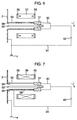
- an insulator 39 is provided in a part of the space between the vacuum vessel 2 and the projection portion 33 so as to electrically insulate the vacuum exhaust element 30 described in Fig. 3 and the vacuum vessel 2 from each other.
- an accident such as a ground fault, or the like
- a large current would not flow into an external power source circuit.
- a fourth embodiment of the present invention with reference to Fig. 8.
- the principle of the operation in this embodiment is similar to that explained about Fig. 3.
- an opening portion 15 of the metal vessel is made smaller than the projection portion 33 of the vacuum exhaust element 30, or a conductor at the same potential as the projection portion 33 is provided in the opening portion. Accordingly, electrons trying to enter the vacuum vessel are repulsed so that the ionizing efficiency is improved while deterioration in insulation can be avoided in the vacuum vessel.
- a grid at the same potential as the projection portion is provided in the opening portion 15 so that electrons are prevented from entering the vacuum vessel. Thus, the influence of sputtering can be further prevented at the beginning of the operation.
- a metallized surface 45 is provided between the projection portion 33 and the insulating portion 31 and between the getter 38 and the insulating portion 31.
- the metallized surface 45 is used as an electron discharge source aggressively. This embodiment has an advantage that the intensity of the electric field is increased locally.
- a high voltage is applied between the high-voltage-side electrode 32 and the low-voltage-side electrode (getter) 38 which are insulated from each other by the insulating portion 31 and disposed through a discharge gap 60.
- the insulating portion 31 When discharge starts, ionized gas is generated.
- the adsorbing efficiency of the getter 38 disposed near the electrode is enhanced.
- a megger 41 which is an insulation resistance meter, is used as the DC power source 43 for the power source circuit 34.
- the megger 41 generates a DC voltage which is applied to the vacuum exhaust element 30.
- the megger 41 is a handy-type measuring instrument for applying a DC voltage of several kV to an insulator and detecting a leakage current to thereby measure a resistance value of M ⁇ level.
- Such a megger is one of measuring instruments which maintainers/managers for high-voltage apparatus usually have.
- a projection portion including an electron generating source is connected to a vacuum vessel grounded, and a getter at the same potential as the projection portion is disposed inside the projection portion. Accordingly, in comparison with a conventional switchgear in which getter material is disposed in a vacuum valve, positive ions are attracted at a high speed by the getter having the same potential as the projection portion. Thus, the exhaust effect is improved. As a result, the reliability against deterioration in vacuum is increased so that it is possible to provide a vacuum switch which is long in life and high in safety.
- the vacuum vessel and a power source circuit are grounded in the present invention, they are always at zero potential, so that the vacuum exhaust element does not need a withstand voltage in which a high voltage is taken into account. That is, it will go well if the vacuum exhaust element has an ordinary withstand voltage. Accordingly, the vacuum exhaust element can be miniaturized. In addition, it is safe for a worker to touch the vacuum exhaust element when maintenance/inspection is carried out.
- the vacuum exhaust element is disposed under one of rods coated with an insulating coating. Accordingly, dust, dirt, and so on, may lie on a bushing but they seldom lie on the vacuum exhaust element. It is therefore unnecessary to clean the vacuum exhaust element frequently.
- the vacuum exhaust element is made shorter than the one of the rods. Accordingly, at the time of manufacture or installation, the longer bushing is the first to collide with a transporter, so as to protect the vacuum exhaust element. Thus, the vacuum exhaust element is hard to be broken.
Landscapes
- High-Tension Arc-Extinguishing Switches Without Spraying Means (AREA)
- Electron Tubes For Measurement (AREA)
- Compressors, Vaccum Pumps And Other Relevant Systems (AREA)
- Particle Accelerators (AREA)
Abstract
Description
Claims (9)
- A vacuum exhaust element (30) of a vacuum switch in which a pair of electrodes (5, 6) are disposed in a vacuum vessel (2) so that one of said electrodes is detachably brought into contact with the other electrode, and rods (5A, 6A) connected with said electrodes (5, 6) extend to the outside from said vacuum vessel (2), said vacuum exhaust element (30) comprising:a projection portion (33) projecting to the outside from a part of said vacuum vessel (2);a magnetic field generator (35, 36) disposed outside said projection portion (33); anda power source circuit (34) connected with an electrode (32) and a getter (38) which are provided in said projection portion (33).
- A vacuum exhaust element (30) of a vacuum switch in which a pair of electrodes (5, 6) are disposed in opposition to each other in a vacuum vessel (2) so that one of said electrodes is detachably brought into contact with the other electrode, and rods (5A, 6A) connected with said electrodes (5, 6) extend to the outside from said vacuum vessel (2) in directions perpendicular to each other, said vacuum exhaust element (30) comprising:a projection portion (33) projecting from a part of said vacuum vessel (2) in the same direction as one (6A) of said rods;a magnetic field generator (35, 36) disposed outside said projection portion (33); anda power source circuit (34) connected with an electrode (32) and a getter (38) which are provided in said projection portion (33).
- A vacuum exhaust element (30) of a vacuum switch in which a pair of electrodes (5, 6) are disposed in opposition to each other in a vacuum vessel (2) so that one of said electrodes is detachably brought into contact with the other electrode, and rods (5A, 6A) connected with said electrodes (5, 6) extend to the outside from said vacuum vessel (2) in directions perpendicular to each other, said vacuum exhaust element (30) comprising:a projection portion (33) projecting from a part of said vacuum vessel (2) in the same direction as one (6A) of said rods;a magnetic field generator (35, 36) disposed outside said projection portion (33); anda power source circuit (34) connected with an electrode (32) and a getter (38) which are provided in said projection portion (33),
wherein said vacuum exhaust element (30) is shorter than said one (6A) of said rods. - A vacuum exhaust element (30) of a vacuum switch in which a pair of electrodes (5, 6) are disposed in opposition to each other in a vacuum vessel (2) so that one of said electrodes is detachably brought into contact with the other electrode, and rods (5A, 6A) connected with said electrodes (5, 6) extend to the outside from said vacuum vessel (2) in directions perpendicular to each other, said vacuum exhaust element (30) comprising:a projection portion (33) projecting from a part of said vacuum vessel (2) in the same direction as one (6A) of said rods;a magnetic field generator (35, 36) disposed outside said projection portion (33); anda power source circuit (34) connected with an electrode (32) and a getter (38) which are provided in said projection portion (33),
wherein said vacuum exhaust element (30) is disposed under said one rod (6A) in opposition to each other. - A vacuum exhaust element (30) of a vacuum switch according to any one of Claims 2 to 4, wherein each of said vacuum vessel (2) and said power source circuit (34) is connected to the ground (E).
- A vacuum exhaust element (30) of a vacuum switch according to any one of Claims 1 to 3, wherein an insulator (39) is put between said vacuum vessel (2) and said projection portion (33).
- A vacuum exhaust element (30) of a vacuum switch according to any one of Claims 1 to 3, wherein said electrode (32) provided in said projection portion (33) is constituted by a high-voltage-side electrode (32) and a low-voltage-side electrode (38) through an electric discharge gap (60).
- A vacuum exhaust element (30) of a vacuum switch according to any one of Claims 1 to 7, wherein a getter layer (38) is provided on an inner wall surface of said projection portion (33).
- A vacuum exhaust element (30) of a vacuum switch according to any one of Claims 1 to 8, wherein an insulation resistance meter (41) is connected to said power source circuit (34).
Applications Claiming Priority (2)
| Application Number | Priority Date | Filing Date | Title |
|---|---|---|---|
| JP28657099A JP3930208B2 (en) | 1999-10-07 | 1999-10-07 | Vacuum insulated switchgear |
| JP28657099 | 1999-10-07 |
Publications (3)
| Publication Number | Publication Date |
|---|---|
| EP1091377A2 true EP1091377A2 (en) | 2001-04-11 |
| EP1091377A3 EP1091377A3 (en) | 2003-05-14 |
| EP1091377B1 EP1091377B1 (en) | 2004-12-22 |
Family
ID=17706130
Family Applications (1)
| Application Number | Title | Priority Date | Filing Date |
|---|---|---|---|
| EP00121794A Expired - Lifetime EP1091377B1 (en) | 1999-10-07 | 2000-10-05 | Vacuum exhaust element of vacuum switch |
Country Status (5)
| Country | Link |
|---|---|
| US (1) | US6495786B1 (en) |
| EP (1) | EP1091377B1 (en) |
| JP (1) | JP3930208B2 (en) |
| CN (1) | CN1305209A (en) |
| DE (1) | DE60016869T2 (en) |
Families Citing this family (5)
| Publication number | Priority date | Publication date | Assignee | Title |
|---|---|---|---|---|
| US6770832B2 (en) * | 2002-12-19 | 2004-08-03 | Eaton Corporation | Vacuum electrical interrupter with pull-to-close mechanism |
| CN201263014Y (en) * | 2008-10-07 | 2009-06-24 | 上海益而益电器制造有限公司 | Creepage protecting socket with reverse wire connection protection function |
| DE102014212583A1 (en) * | 2014-06-30 | 2015-12-31 | Siemens Aktiengesellschaft | Avoid misalignment of a drive rod of a circuit breaker |
| DE112015006910B4 (en) | 2015-09-16 | 2023-03-30 | Hitachi High-Tech Corporation | vacuum device |
| US10566158B2 (en) * | 2017-12-13 | 2020-02-18 | Finley Lee Ledbetter | Method for reconditioning of vacuum interrupters |
Family Cites Families (9)
| Publication number | Priority date | Publication date | Assignee | Title |
|---|---|---|---|---|
| NL106773C (en) * | 1956-09-29 | |||
| DE1033757B (en) * | 1957-09-28 | 1958-07-10 | Siemens Ag | Vacuum switch with built-in ionization getter pump |
| DE2002685A1 (en) * | 1969-07-30 | 1971-03-25 | Inst Prueffeld Fuer Elek Sche | Method and device for checking the gas pressure in vacuum interrupter chambers |
| JPS51130873A (en) | 1975-05-12 | 1976-11-13 | Tokyo Shibaura Electric Co | Vacuum switch |
| US4163130A (en) * | 1975-07-25 | 1979-07-31 | Hitachi, Ltd. | Vacuum interrupter with pressure monitoring means |
| NL170995C (en) * | 1978-12-01 | 1983-01-17 | Hazemeijer Bv | VACUUM SWITCH, METAL SCREEN AND CATCH ELEMENT THEREFOR. |
| JPH0685291B2 (en) * | 1988-04-01 | 1994-10-26 | 株式会社日立製作所 | Vacuum circuit breaker |
| US5387772A (en) * | 1993-11-01 | 1995-02-07 | Cooper Industries, Inc. | Vacuum switch |
| TW405135B (en) * | 1998-03-19 | 2000-09-11 | Hitachi Ltd | Vacuum insulated switch apparatus |
-
1999
- 1999-10-07 JP JP28657099A patent/JP3930208B2/en not_active Expired - Fee Related
-
2000
- 2000-09-30 CN CN00137033A patent/CN1305209A/en active Pending
- 2000-10-03 US US09/677,602 patent/US6495786B1/en not_active Expired - Lifetime
- 2000-10-05 DE DE60016869T patent/DE60016869T2/en not_active Expired - Lifetime
- 2000-10-05 EP EP00121794A patent/EP1091377B1/en not_active Expired - Lifetime
Also Published As
| Publication number | Publication date |
|---|---|
| EP1091377A3 (en) | 2003-05-14 |
| DE60016869T2 (en) | 2005-12-08 |
| JP2001110286A (en) | 2001-04-20 |
| JP3930208B2 (en) | 2007-06-13 |
| EP1091377B1 (en) | 2004-12-22 |
| CN1305209A (en) | 2001-07-25 |
| US6495786B1 (en) | 2002-12-17 |
| DE60016869D1 (en) | 2005-01-27 |
Similar Documents
| Publication | Publication Date | Title |
|---|---|---|
| KR100546032B1 (en) | Vacuum Insulated Switchgear | |
| US6426627B2 (en) | Vacuum switch including vacuum-measurement devices, switchgear using the vacuum switch, and operation method thereof | |
| CN105122412B (en) | Vacuum interrupter, switching method thereof and electric switch cabinet | |
| JP7118992B2 (en) | vacuum switch | |
| JP2001307603A (en) | Vacuum switch and vacuum switchgear using the same | |
| EP1022761B1 (en) | Vacuum switching apparatus | |
| US6884940B1 (en) | Vacuum switchgear | |
| JPS58145035A (en) | Vacuum arc discharge device | |
| EP1091377B1 (en) | Vacuum exhaust element of vacuum switch | |
| CA3028224C (en) | Switch having an arc-quenching device | |
| JP3395698B2 (en) | Vacuum insulated switchgear | |
| JP2001110286A5 (en) | ||
| EP1119009A1 (en) | Vacuum switch and vacuum switch gear | |
| US20210350989A1 (en) | Electromagnetic drive for a power circuit-breaker with a vacuum interrupter | |
| JPH07220586A (en) | High voltage equipment | |
| JP2025177112A (en) | Vacuum valve | |
| US9558900B2 (en) | Vacuum assisted electrical disconnect with dynamic shield | |
| JP2023554041A (en) | Electrical switchgear for medium and/or high voltage applications | |
| JPH0224927A (en) | Disconnecting switch | |
| WO2021070409A1 (en) | Disconnector and gas-insulated switchgear | |
| JPH07288071A (en) | Switch | |
| JPH04174920A (en) | Vacuum circuit breaker | |
| HK1071471B (en) | Vacuum insulated switching apparatus |
Legal Events
| Date | Code | Title | Description |
|---|---|---|---|
| PUAI | Public reference made under article 153(3) epc to a published international application that has entered the european phase |
Free format text: ORIGINAL CODE: 0009012 |
|
| AK | Designated contracting states |
Kind code of ref document: A2 Designated state(s): AT BE CH CY DE DK ES FI FR GB GR IE IT LI LU MC NL PT SE |
|
| AX | Request for extension of the european patent |
Free format text: AL;LT;LV;MK;RO;SI |
|
| PUAL | Search report despatched |
Free format text: ORIGINAL CODE: 0009013 |
|
| AK | Designated contracting states |
Designated state(s): AT BE CH CY DE DK ES FI FR GB GR IE IT LI LU MC NL PT SE |
|
| AX | Request for extension of the european patent |
Extension state: AL LT LV MK RO SI |
|
| 17P | Request for examination filed |
Effective date: 20031106 |
|
| 17Q | First examination report despatched |
Effective date: 20031204 |
|
| AKX | Designation fees paid |
Designated state(s): DE FR |
|
| GRAP | Despatch of communication of intention to grant a patent |
Free format text: ORIGINAL CODE: EPIDOSNIGR1 |
|
| RIN1 | Information on inventor provided before grant (corrected) |
Inventor name: MORITA, AYUMU,HITACHI, LTD.,INTEL. PROP. GROUP Inventor name: KOJIMA, KATSUNORI,HITACHI LTD.,INTE. PROP. GROUP Inventor name: YOTSUMOTO, YOSHIHARU,TOKYO ELECTRIC POWER CO. INC Inventor name: TSUJI, MASASHIGE,HITACHI,LTD.,INTEL. PROP. GROUP Inventor name: ISHIKAWA, YUICHI,HITACHI LTD.,INTEL. PROP. GROUP Inventor name: TANAMIZU, TORU,HITACHI, LTD.,INTEL. PROP. GROUP |
|
| GRAS | Grant fee paid |
Free format text: ORIGINAL CODE: EPIDOSNIGR3 |
|
| GRAA | (expected) grant |
Free format text: ORIGINAL CODE: 0009210 |
|
| AK | Designated contracting states |
Kind code of ref document: B1 Designated state(s): DE FR |
|
| REG | Reference to a national code |
Ref country code: IE Ref legal event code: FG4D |
|
| REF | Corresponds to: |
Ref document number: 60016869 Country of ref document: DE Date of ref document: 20050127 Kind code of ref document: P |
|
| PLBE | No opposition filed within time limit |
Free format text: ORIGINAL CODE: 0009261 |
|
| STAA | Information on the status of an ep patent application or granted ep patent |
Free format text: STATUS: NO OPPOSITION FILED WITHIN TIME LIMIT |
|
| 26N | No opposition filed |
Effective date: 20050923 |
|
| ET | Fr: translation filed | ||
| REG | Reference to a national code |
Ref country code: FR Ref legal event code: PLFP Year of fee payment: 17 |
|
| REG | Reference to a national code |
Ref country code: DE Ref legal event code: R082 Ref document number: 60016869 Country of ref document: DE Representative=s name: STREHL SCHUEBEL-HOPF & PARTNER MBB PATENTANWAE, DE Ref country code: DE Ref legal event code: R081 Ref document number: 60016869 Country of ref document: DE Owner name: HITACHI INDUSTRIAL EQUIPMENT SYSTEMS CO., LTD., JP Free format text: FORMER OWNER: HITACHI, LTD., TOKYO, JP |
|
| REG | Reference to a national code |
Ref country code: FR Ref legal event code: PLFP Year of fee payment: 18 |
|
| REG | Reference to a national code |
Ref country code: FR Ref legal event code: TP Owner name: HITACHI INDUSTRIAL EQUIPMENT SYSTEMS CO., LTD., JP Effective date: 20171023 |
|
| REG | Reference to a national code |
Ref country code: FR Ref legal event code: PLFP Year of fee payment: 19 |
|
| PGFP | Annual fee paid to national office [announced via postgrant information from national office to epo] |
Ref country code: FR Payment date: 20190913 Year of fee payment: 20 |
|
| PGFP | Annual fee paid to national office [announced via postgrant information from national office to epo] |
Ref country code: DE Payment date: 20190924 Year of fee payment: 20 |
|
| REG | Reference to a national code |
Ref country code: DE Ref legal event code: R071 Ref document number: 60016869 Country of ref document: DE |