EP1091321A2 - Apparatus and method for drawing lines on a digital display - Google Patents
Apparatus and method for drawing lines on a digital display Download PDFInfo
- Publication number
- EP1091321A2 EP1091321A2 EP00121797A EP00121797A EP1091321A2 EP 1091321 A2 EP1091321 A2 EP 1091321A2 EP 00121797 A EP00121797 A EP 00121797A EP 00121797 A EP00121797 A EP 00121797A EP 1091321 A2 EP1091321 A2 EP 1091321A2
- Authority
- EP
- European Patent Office
- Prior art keywords
- data
- line
- storage means
- data storage
- coordinate
- Prior art date
- Legal status (The legal status is an assumption and is not a legal conclusion. Google has not performed a legal analysis and makes no representation as to the accuracy of the status listed.)
- Withdrawn
Links
Images









Classifications
-
- G—PHYSICS
- G06—COMPUTING OR CALCULATING; COUNTING
- G06T—IMAGE DATA PROCESSING OR GENERATION, IN GENERAL
- G06T11/00—Two-dimensional [2D] image generation
- G06T11/20—Drawing from basic elements
- G06T11/23—Drawing from basic elements using straight lines or curves
Definitions
- the present invention generally relates to a graphics processor for drawing lines as a graphic image on a display device, for example, and more particularly relates to an apparatus that can draw relatively short lines in a shorter amount of time.
- a car navigation system in particular, often needs to present map information (e.g., roads, boundaries, etc. on the map) on the screen as a combination of many short lines, not just simple straight lines (or line segments).
- map information e.g., roads, boundaries, etc. on the map
- the user's demand for accelerated line drawing by a graphics processor has been rising in the field of navigation systems. This is because he or she almost always wants to retrieve information about an area neighboring that currently presented on the screen as fast as possible.
- Figure 25 illustrates a basic procedure taken by the known line-drawing method.
- a start point 100 with coordinates (Xs, Ys) and an end point 101 with coordinates (Xe, Ye) are given on the screen.
- a (linear) slope parameter, representing the slope of the line needs to be calculated from these coordinates as
- the line is drawn as a group of line segments 102 with a unit length that are joined together between the start and end points 100 and 101 .
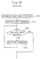
- Figure 26 illustrates a typical flow of the known line-drawing process.
- the directional attribute of a line is determined. Specifically, the shifting direction of the line is known from the signs of the differences between the X coordinates and between the Y coordinates of the start and end points 100 and 101 , i.e., (Xe ⁇ Xs) and (Ye ⁇ Ys).
- the slope parameter of the line is obtained by dividing the absolute value of the difference between the Y coordinates by that of the difference between the X coordinates, i.e.,
- Step S102 it is determined whether or not the far end of the line being drawn has reached the end point 101 . If the answer is NO, then the slope parameters obtained are sequentially added together from the start point 100 in the next Step S103 .
- the inventive line-drawing apparatus presents a midpoint between the start and end points of a line by generating the coordinates of the point. Then, the apparatus sequentially presents other midpoints by generating their coordinates such that each midpoint is located between the midpoint previously generated and one of the other points adjacent to the midpoint.
- a first inventive line-drawing apparatus is adapted to draw a line connecting a start point to an end point.
- the start and end points are represented by mutually different sets of coordinates.
- the apparatus includes midpoint coordinate generating means for generating coordinates for first, second and third midpoints.
- the first midpoint is located in the middle of a line segment connecting the start and end points together.
- the second midpoint is located in the middle of a line segment connecting the start point and the first midpoint together.
- the third midpoint is located in the middle of a line segment connecting the end point and the first midpoint together.
- the apparatus further includes display means for presenting the start point, the first, second and third midpoints and the end point thereon.
- the midpoint coordinate generating means In the first line-drawing apparatus, first, the midpoint coordinate generating means generates coordinates for a first midpoint located in the middle of a line segment connecting start and end points together. And then the generating means sequentially generates coordinates for other midpoints, each located in the middle of a line segment connecting two adjacent points together.
- the throughput improves particularly when many short lines should be drawn.
- the divide-by-two operation for obtaining each midpoint may be performed just by shifting right by one bit as for a binary number, the configuration of the apparatus can be simplified and the cost thereof can be cut down.
- the midpoint coordinate generating means further generates coordinates for other midpoints, each being located in the middle of a line segment ending at two adjacent ones of the points. In such an embodiment, even if the line to be drawn is relatively long, the line still can be drawn with higher precision.
- the line connecting the start and end points together is preferably divided into a number 2 n of line segments, where n is an integer equal to or greater than zero. And each said line segment is preferably further divided by two with the line segment regarded as ending at a new pair of start and end points.
- n is an integer equal to or greater than zero.
- each said line segment is preferably further divided by two with the line segment regarded as ending at a new pair of start and end points.
- At least one midpoint is obtained by dividing the line connecting the start and end points together into a number 2 n of line segments, where n is an integer greater than zero.
- Each said midpoint obtained is located in the middle of a line segment connecting two of the other points, where one of the two points is located closer to the start point while the other is located closer to the end point.
- a second inventive line-drawing apparatus is also adapted to draw a line connecting a start point to an end point.
- the start and end points are both presented on display means and represented by mutually different sets of coordinates.
- the apparatus includes: first and second data storage means, each accepting a plurality of input coordinate data and sequentially outputting one item of these data after another on a first in, first out basis; adding means for receiving and adding together the respective coordinate data output from the first and second data storage means and outputting added data; and divide-by-two means for dividing the added data by two and outputting divided data.
- the coordinate data output from the first and second data storage means are input to the first data storage means.
- the divided data is input from the divide-by-two means to the second storage means.
- the line connecting the start and end points together is drawn on the display means in accordance with the divided data output from the divide-by-two means.
- the second line-drawing apparatus coordinate data, representing the start and end points, are output and stored on the first and second data storage means concurrently.
- the output data of the first and second data storage means i.e., the coordinate data representing the start and end points
- the coordinate data representing the start and end points are stored on the first data storage means, while the divided coordinate data, representing the first midpoint, is stored on the second data storage means. Since these data storage means are FIFOs, the first and second data storage means will next output the coordinate data representing the start or end point and the coordinate data representing the first midpoint, respectively.
- the second inventive line-drawing apparatus performs the same operation as the first inventive line-drawing apparatus.
- the divide-by-two means is preferably a shifter that is so interconnected as to shift the added data to the right by one bit.
- the divide-by-two means is implementable as a shifter (e.g., a barrel shifter) that can operate at a high speed using a simple configuration.
- the inventive apparatus can consist of relatively simple hardware resources including the adding means as primary components.
- the second apparatus may further include iteration control means for regulating the number of times the output data is fed back to the first and second storage means.
- the iteration control means may include: a longer side calculator/selector for calculating respective absolute values of a difference between X coordinates and a difference between Y coordinates of the start and end points and for outputting one of these two differences that has the greater absolute value; and a number-of-times comparator for determining, by the absolute value, the number of times the output should be fed back.
- the longer side calculator/selector selects either the difference between the X coordinates or the difference between the Y coordinates that has the greater absolute value for the start and end points.
- the number of midpoints formed between the start and end points is controllable depending on the absolute values of the differences between the X coordinates and between the Y coordinates, thus increasing the line-drawing precision.
- the number-of-times comparator determines the required number of times of feedback by the difference with the greater absolute value, the line-drawing process can be finished within a predetermined amount of time.
- the second apparatus may further include: first and second color data storage means, each accepting a plurality of input color data and sequentially outputting one of the data after another on a first in, first out basis; color data adding means for receiving and adding together the respective color data output from the first and second color data storage means and outputting added color data; and color data divide-by-two means for dividing the added color data by two and outputting divided color data.
- the color data which are output from the first and second color data storage means and correspond to the start and end points, respectively, are input to the first color data storage means.
- the divided color data, output from the color data divide-by-two means is input to the second color data storage means.
- the color of the line connecting the start and end points together may be determined in accordance with the divided color data.
- color information is also processed digitally by a computer.
- the added color data is also divided by two, while the line connecting the start and end points together is being drawn.
- a color-interpolated, graded line can be drawn within a period of time required by the conventional division operation.
- the second line-drawing apparatus may further include: first and second brightness data storage means, each accepting a plurality of input brightness data and sequentially outputting one of the data after another on a first in, first out basis; brightness data adding means for receiving and adding together the respective brightness data output from the first and second brightness data storage means and outputting added brightness data; and brightness data divide-by-two means for dividing the added brightness data by two and outputting divided brightness data.
- the brightness data which are output from the first and second brightness data storage means and correspond to the start and end points, respectively, are input to the first brightness data storage means.
- the divided brightness data, output from the brightness data divide-by-two means is input to the second brightness data storage means.
- the brightness of the line connecting the start and end points together may be determined in accordance with the divided brightness data.
- brightness information is also processed digitally by a computer.
- the added brightness data is also divided by two, while the line connecting the start and end points together is being drawn.
- a brightness-interpolated, graded line can be drawn within a period of time required by the conventional division operation.
- the second line-drawing apparatus may further include: linear parameter calculating means for calculating and outputting a linear parameter representing a slope of the line connecting the start and end points together; first selecting means for receiving the linear parameter and the output data of the first data storage means and selectively outputting either the parameter or the output data of the first data storage means to the adding means; and second selecting means for receiving the divided data and the output data of the second data storage means and selectively outputting either the divided data or the output data of the second data storage means to the adding means.
- the apparatus includes the linear parameter calculating means for calculating and outputting a linear parameter representing the slope of the line connecting the start and end points together.
- a third inventive line-drawing apparatus is also adapted to draw a line connecting a start point to an end point.
- the start and end points are both presented on display means and both represented by mutually different sets of coordinates.
- the apparatus includes: data storage means with data storage areas on which multiple coordinate data are storable, the coordinate data including first and second coordinate data of the line connecting the start and end points together; adding means for adding together the first and second coordinate data and outputting added data; and divide-by-two means for dividing the added data by two and outputting divided data.
- the divided data is stored as third coordinate data on a predetermined one of the data storage areas.
- data storage means includes data storage areas, on which multiple coordinate data, including first and second coordinate data of a line connecting start and end points together, are storable. Accordingly, the number of midpoints to be generated is automatically determined by the number of the data storage areas (i.e., capacity). As a result, the procedure of computations is simplified and controllable more easily.
- the adding and divide-by-two means repeatedly perform the addition and the divide-by-two operation for multiple line segments a number of times determined by the number of the data storage areas. Each said line segment ends at two adjacent ones of midpoints that correspond to the respective coordinate data. And results of the addition and the divide-by-two operation are stored on respectively predetermined ones of the data storage areas. In such an embodiment, even if a line segment to be drawn is relatively long, the line segment can be drawn with higher precision.
- An inventive line-drawing method is adapted to draw a line connecting a start point to an end point using a line-drawing apparatus.
- the apparatus includes: display means; first and second data storage means of a first in, first out type; adding means for receiving outputs of the first and second data storage means; and divide-by-two means for dividing an output of the adding means by two.
- the start and end points are both presented on the display means and represented by mutually different sets of coordinates.
- the method includes the steps of: a) outputting start and end point coordinate data, which represent the start and end points, respectively, to the display means; b) storing the start and end point coordinate data on the first and second data storage means, respectively; c) outputting the start point coordinate data from the first data storage means to the adding means and storing the start point coordinate data back to the first storage means concurrently; d) outputting the end point coordinate data from the second data storage means to the adding means and storing the end point coordinate data on the first storage means concurrently; e) outputting a sum of the start and end point coordinate data from the adding means to the divide-by-two means; and f) providing output data of the divide-by-two means to the display means and storing the output data of the divide-by-two means on the second data storage means concurrently such that the output data of the divide-by-two means corresponds to the start and end point coordinate data stored in the steps c) and d).
- Figure 1 illustrates a configuration for a line-drawing apparatus of the first embodiment.
- the line-drawing apparatus includes parameter register 1 , X and Y coordinate generators 2 and 3 , address converter 4 , memory interface 5 , frame memory 6 and image display 7 .
- Coordinate data representing an image to be drawn, is temporarily stored on the parameter register 1.
- X and Y coordinates, included in the coordinate data, are generated by the X and Y coordinate generators 2 and 3 , respectively.
- the address converter 4 converts the two-dimensional coordinate data, generated by the X and Y coordinate generators 2 and 3 , into one-dimensional coordinate data, which is passed to, and stored on, the frame memory 6 for storing image frames via the memory interface 5 .
- the coordinate data is eventually presented on the image display 7 such as a liquid crystal display panel or a CRT.
- the memory interface 5 stops outputting the coordinate data to the frame memory 6 .
- Figure 2 illustrates the details of the X coordinate generator 2 shown in Figure 1 .
- the Y coordinate generator 3 also has a similar configuration to that of the X coordinate generator 2 .
- the X coordinate generator 2 includes first and second FIFO memories 11 and 12 , X coordinate calculator 13 , X coordinate controller 14 and selector 15 .
- the first and second FIFO memories 11 and 12 may receive the X coordinates of the start and end point coordinate data, respectively, from the parameter register 1 and store them thereon.
- the X coordinate calculator 13 receives and adds together the output data of the first and second FIFO memories 11 and 12 , divides the sum by two and then outputs the quotient.
- the X coordinate controller 14 is an exemplary iteration control means for controlling the iterative operation of the first and second FIFO memories 11 and 12 , for example, as defined in the appended claims.
- the selector 15 receives the two output data of the parameter register 1 and the output data of the X coordinate calculator 13 and selectively outputs one of these three data in response to a select signal supplied from the X coordinate controller 14 .
- the first FIFO memory 11 includes first and second memory cells 11a and 11b .
- One of the two output data of the parameter register 1 and the output data of the second FIFO memory 12 are input to the first memory cell 11a .
- the output data of the first memory cell 11a and that of the first FIFO memory 11 are input to the second memory cell 11b .
- the second FIFO memory 12 also includes first and second memory cells 12a and 12b .
- the other output data of the parameter register 1 and the output data of the X coordinate calculator 13 are input to the first memory cell 12a .
- the output data of the first memory cell 12a and that of the X coordinate calculator 13 are input to the second memory cell 12b . It should be noted that the same operation is executable even if the first and second FIFO memories 11 and 12 have their positions interchanged horizontally.
- the X coordinate calculator 13 includes an adder 21 and a shifter 22 .
- the adder 21 receives and adds together the output data of the first and second FIFO memories 11 and 12 .
- the shifter 22 is an exemplary divide-by-two means for dividing the sum by two as defined in the appended claims.
- the shifter 22 preferably has the configuration shown in Figure 3 .
- the shifter 22 preferably includes a one-bit line shifter 22a and a data latch 22b .
- the one-bit line shifter 22a is a barrel shifter, which has been so interconnected as to be shifted right by one bit such that the input data can be shifted to the right by one bit.
- the data latch 22b latches the output values of the one-bit line shifter 22a bit by bit and output them as serial data.
- the circuit configuration of the shifter 22 can be simplified and the input can be divided by two at a higher speed.
- Figure 4 illustrates the details of the X coordinate controller 14 .
- the X coordinate controller 14 includes iterative number regulator 25 and first and second FIFO controllers 26A and 26B .
- the iterative number regulator 25 determines how many times the output data should be fed back to the first and second FIFO memories 11 and 12 , i.e., the number of times the operation of obtaining a midpoint should be performed.
- the first and second FIFO controllers 26A and 26B control the input and output of data to/from the first and second FIFO memories 11 and 12 , respectively.
- Figure 5 illustrates the details of the iterative number regulator 25 .
- the iterative number regulator 25 includes longer side calculator/selector 25a , number-of-times comparator 25b and operation controller 25c .
- the longer side calculator/selector 25a receives the start and end point coordinates (Xs, Ys) and (Xe, Ye) of a line to be drawn from the parameter register 1 , the longer side calculator/selector 25a obtains the absolute values of the difference between the X coordinates and the difference between the Y coordinates of these two points, i.e.,
- the longer side calculator/selector 25a selectively outputs the data corresponding to the longer side.
- the number-of-times comparator 25b determines, by the value of the longer side, the number of times the operation should be performed and outputs the number.
- the operation controller 25c gets a predetermined operation executed by the X coordinate calculator 13 the given number of times.
- Figure 6 illustrates an exemplary configuration for the number-of-times comparator 25b and operation controller 25c .
- the number-of-times comparator 25b includes a ROM table 251.
- the operation controller 25c includes counter 252 , comparator 253 and iterative number control signal output circuit 254 .
- the value of the longer side and the predetermined number of times the operation should be performed (which number has been determined by the longer-side value) are stored on the ROM table 251.
- the counter 252 counts the number of times the operation has actually been performed.
- the comparator 253 compares the predetermined number of times, which has been read out from the ROM table 251 , to the count output from the counter 252 . If the count is still less than the predetermined number, then the comparator 253 outputs an execute signal. Alternatively, if the count is already equal to or greater than the predetermined number, then the comparator 253 outputs an end-of-operation signal.
- the iterative number control signal output circuit 254 In response to the execute signal, the iterative number control signal output circuit 254 outputs a counter control signal to the counter 252 to instruct the counter 252 to keep counting, and also outputs the execute signal to the first and second FIFO controllers 26A and 26B .
- the iterative number control signal output circuit 254 On receiving the end-of-operation signal, the iterative number control signal output circuit 254 outputs an initialize signal to the counter 252 to instruct the counter 252 to reset the count and also outputs the end-of-operation signal to the first and second FIFO controllers 26A and 26B .
- the ROM table 251 does not have to be a table on a memory area, but may be a logic circuit that receives the longer-side value and outputs the number of times determined by the longer-side value.
- the number of memory cells in each of the FIFO memories 11 and 12 (which will be herein referred to as the "number of FIFO stages") is four.
- the number of FIFO stages is represented by X and Y coordinates.
- each midpoint of a line which is represented by X and Y coordinates, will be herein called a "line point”. That is to say, the "longer-side value" is the number of line points that together make the line.
- Figure 7 schematically illustrates how the value of the longer side to be drawn increases with the increase in number of FIFO stages.
- Table 2 illustrates an exemplary iterative number determination table (i.e., example of the ROM table 251 ) used to determine, by the longer-side value output from the longer side calculator/selector 25a , how many times the operation should be performed repeatedly for an FIFO memory with four stages.
- FIGs 8(a) through 8(d) schematically illustrate how to generate the coordinates for start point, end point and other midpoints.
- the start and end point coordinate data are identified by 30 and 31 , respectively.
- first midpoint coordinate data 32 represents a midpoint of a line segment connecting the start and end points that are represented by the coordinate data 30 and 31 , respectively.
- second midpoint coordinate data 33 represents a midpoint of a line segment connecting the start point and the first midpoint that are represented by the coordinate data 30 and 32 , respectively.
- third midpoint coordinate data 34 represents a midpoint of a line segment connecting the end point and the first midpoint that are represented by the coordinate data 31 and 32 , respectively.
- Figure 8(d) illustrates the coordinate data finally defined for these five pixels.
- the "pixel" refers to a point essential for a line to be drawn.
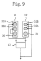
- Figure 9 schematically illustrates how the coordinate data 30 through 34 are stored on the first and second FIFO memories 11 and 12 .
- the same components as those illustrated in Figure 2 will be identified by the same reference numerals and the description thereof will be omitted herein.
- the coordinate data 30 and 31 for the start and end points to be drawn with respective coordinates (Xs, Ys) and (Xe, Ye) are input to, and stored on, the parameter register 1 .
- Xs data i.e., the X coordinate of the start point
- the X coordinate controller 14 instructs the selector 15 to output the Xs data to the address converter 4 shown in Figure 1 .
- Xe data i.e., the X coordinate of the end point
- the second FIFO memory 12 while the X coordinate controller 14 instructs the selector 15 to output the Xe data to the address converter 4 along with the Xs data.
- the start and end point coordinate data 30 and 31 are respectively input from the first and second FIFO memories 11 and 12 to the X coordinate calculator 13 .
- the start point coordinate data 30 which is output from the first FIFO memory 11
- the end point coordinate data 31 which is output from the second FIFO memory 12
- data 31A is input again as data 31A to the first FIFO memory 11 .
- these data are identified by different reference numerals 30A and 31A for illustrative purposes, these data have the same data values as the start and end point coordinate data 30 and 31 , respectively.
- the same statement is applicable to data 32A and 32B to be described below.
- the X coordinate calculator 13 adds together the start and end point coordinate data 30 and 31 and divides the sum by two, thereby outputting first midpoint coordinate data 32 .
- the first midpoint coordinate data 32 is input again to the two memory cells in the second FIFO memory 12 and stored thereon as data 32A and 32B .
- the first midpoint coordinate data 32 shown in Figure 8(b) is generated.
- the end point coordinate data 31A and the first midpoint coordinate data 32B are respectively input from the first and second FIFO memories 11 and 12 to the X coordinate calculator 13 .
- the third midpoint coordinate data 34 shown in Figure 8(c) is generated.
- the X coordinate calculator 13 has to perform the add-and-divide-by-two operation three times.
- the address converter 4 converts the two-dimensional coordinates, consisting of the X and Y coordinates output from the X and Y coordinate generators 2 and 3 , respectively, into one-dimensional coordinates as shown in Figure 1 .
- These one-dimensional coordinates are written as a frame image on the frame memory 6 by way of the memory interface 5 . And the image is eventually presented on the image display 7 .
- Figure 10(a) schematically illustrates the first FIFO memory 11 with four FIFO stages.
- the second FIFO memory 12 may also have a configuration similar to that illustrated in Figure 10(a) for the first FIFO memory 11 .
- the number of FIFO stages should be determined in advance by the longer-side value of a line to be drawn by the line-drawing apparatus. For example, as shown in Table 1, if the line has a longer-side value of 5, then each FIFO memory should have four stages. And if the line has a longer-side value of 9, then each FIFO memory should have eight stages.
- the first FIFO memory 11 preferably has the configuration shown in Figure 10(a) .
- the first FIFO memory 11 includes data storage section 111 and end mark storage section 112 .
- the data storage section 111 has memory areas with a width of at least 8 bits, while the end mark storage section 112 has memory areas with a width of 1 bit.
- the fifth stage of the end mark storage section 112 is an overflow section 113 .
- Data input to the data storage section 111 is stored on a vacant area adjacent to the area where valid data has already been stored.
- data, which is output first from the data storage section 111 is on the first one of the stages where valid data have been stored.
- a single data unit is output by shifting the data on the first stage of the data storage section 111 downward by one stage.
- the data “0" on the first stage is output from the memory 11
- each of the data "8" and "4" and the end mark "1" is shifted downward by one stage.
- two data units "2" and "1" are input to the data storage section 111
- these data units are stored on the third and fourth stages of the data storage section 111 , respectively, and the end mark "1" is shifted upward by two stages to be stored on the overflow section 113 as shown on the right-hand side of Figure 10(a) .
- Figure 10(b) illustrates the flow of data from the parameter register 1 to the X coordinate calculator 13 through the first and second FIFO memories 11 and 12 with such a configuration.
- the data is input to each of the FIFO memories 11 and 12 via a selector MPX and output from each of the FIFO memories 11 and 12 by way of a buffer.
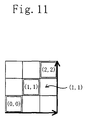
- Figure 11 illustrates an example in which the start and end point coordinate data (Xs, Ys) and (Xe, Ye) are (0, 0) and (2, 2), respectively.
- midpoint coordinate data (1, 1) is generated just by performing the operation only once for three pixels as shown in Figure 11 .
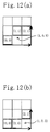
- Figure 12(a) illustrates an example in which the start and end point coordinate data (Xs, Ys) and (Xe, Ye) are (0, 0) and (2, 1), respectively.
- a decimal point calculation will result in a midpoint with coordinate data (1, 0.5).
- the resulting data is raised (or rounded) to generate midpoint coordinate data (1, 1).
- the rounding operation may be performed by providing below-decimal-point bit domains for the shifter 22 shown in Figure 3 and by adding one to one bit below the decimal point. Specifically, if the one bit below the decimal point is "0" after shifting, no carries will be caused. Alternatively, if the one bit is "1", carries will be caused and 0.5 will be raised to 1.
- Figure 12(b) illustrates an example in which the calculated data (1, 0.5) is truncated to generate alternative midpoint coordinate data (1, 0).
- This data is output when no below-decimal-point bit domains are provided for the shifter 22 . That is to say, the shifter 22 shown in Figure 3 generates this data.
- Figure 13(a) illustrates an example in which the start and end point coordinate data (Xs, Ys) and (Xe, Ye) are (0, 0) and (2, 3), respectively.
- the midpoint coordinate data to be generated step by step will be enumerated below.
- an arithmetic sign "#" means an arithmetic operation of dividing a sum of two data by two. Also, in the following example, data with a decimal fraction is rounded (or raised).
- Figure 13(b) illustrates midpoint coordinate data resulting from truncation.
- the X and Y coordinate generators 2 and 3 are separately provided to perform calculation for respective coordinates.
- X and Y coordinates are mutually independent data, just one of these coordinate generators may be provided and used repeatedly.
- a short line can be drawn without performing the division operation of calculating a linear parameter for the line. That is to say, since many clock cycles, which are usually required for the division operation, are not needed, short line drawing can be started while the division cycles are still being executed according to the conventional technique. Thus, the coordinates of a line can be calculated at a higher speed. Particularly when a large number of short lines should be drawn, much more computational process is executable within a predetermined amount of time. As a result, the throughput of the drawing process can be improved considerably.
- the FIFO memories are used for storing data to be passed to the X coordinate calculator 13 .
- any other data storage means may be used instead of the FIFO memories so long as the storage means can pass the same data as the stored one.
- Figure 14(a) schematically illustrates a fixed memory for storing thereon the data to be passed to the X coordinate calculator 13 .
- the fixed memory 45 i.e., exemplary data storage means as defined in the claims, has its number of stages determined in advance by the longer-side value of a line to be drawn by the line-drawing apparatus. For example, if the longer-side value is 9, then a data storage section with nine stages is needed as shown in Figure 14(a) . If the longer-side value is 17, then a storage section with 17 stages is needed.
- the method using an FIFO memory needs a storage section with a number m of stages (where m is a positive integer)
- the method using a fixed memory needs a storage section with a number m+1 stages.
- the fixed memory 45 is implementable as a single block, whereas the method using the FIFO memories needs two blocks.
- Figure 14(b) illustrates the order in which the coordinate data should be stored on the fixed memory 45 .
- the storage areas for the start and end points 1 and 9 of a line to be drawn are determined.
- the coordinate data of the start and end points 1 and 9 are stored on the data storage areas A1 and A9 , respectively.
- the X coordinate calculator 13 including the adder 21 and the shifter 22 shown in Figure 2 , performs the addition and the divide-by-two operation to obtain the coordinate data of the first midpoint 5 between the start and end points 1 and 9 and store the data on the data storage area A5 . Subsequently, following the order of calculation shown in Figure 14(b) , the data of the second midpoint 3 between the start point 1 and the first midpoint 5 is stored on the data storage area A3 and then a similar operation will be performed sequentially. In Figure 14(b) , (A5) denotes the data stored on the data storage area A5 .
- the coordinate data of the midpoints do not have to be calculated in the order shown in Figure 14(b) , but may be calculated in any arbitrary order so long as the coordinate data already obtained is used.
- the data storage areas A1 through A9 of the fixed memory 45 are arranged in the ascending or descending order of the addresses for the memory (i.e., from the start point toward the end point).
- the data storage areas A1 through A9 may be arranged in any order so long as one-to-one correspondence is established between the data obtained and their storage areas.
- each pair of data storage areas does not have to be adjacent to each other.
- control can be simplified compared to the method using the FIFO memories, because the same method is applicable to the calculation of midpoints and the memory is fixed.
- Figure 15 illustrates a configuration for a line-drawing apparatus of the second embodiment.
- this apparatus further includes a color information generator 8 , which has a similar configuration to that of the X and Y coordinate generators 2 and 3 , between the parameter register 1 and the memory interface 5 .
- the line-drawing apparatus of the second embodiment can perform color interpolation on a line connecting start and end points where color information is added to the coordinate data representing the line including the start and end points.
- the X and Y coordinates of the start and end point coordinate data are input to the X and Y coordinate generators 2 and 3 .
- the operation is performed a predetermined number of times to obtain the coordinate data representing the first, second, third midpoints and so on, which are subsequently output to the address converter 4 .
- the color data values of the start and end point coordinate data are input to the color information generator 8 .
- the color information generator 8 adds together the numerical values representing the colors of the start and end points and divides the sum by two, thereby outputting a piece of color interpolation information.
- the color information generator 8 may have the same configuration as the X coordinate generator 2 shown in Figure 2 . That is to say, in this case, the first and second FIFO memories 11 and 12 , adder 21 and shifter 22 function as first and second color data storage means, color data adding means and color data divide-by-two means, respectively.
- the interpolation information which has been generated by the color information generator 8 , is combined with its associated coordinate data in the frame memory 6 . Then, a pixel in the specified color is drawn on the image display 7 .
- Figure 16 illustrates an exemplary line that has been drawn with various gradations, or with its colors interpolated.
- the "gradation” refers to gradual change in colors of separately located, discrete objects with the interpolation.
- the midpoint with the coordinates (1, 1) between the dark-colored start point with the coordinates (0, 0) and the light-colored end point with the coordinates (2, 2) has color data representing an intermediate color between them.
- Figure 17 illustrates a modified example of the color information generator 8 .
- the color information generator 8 shown in Figure 17 includes red, green and blue information generators 8a , 8b and 8c , each having the same configuration as that of the X coordinate generator 2 .
- red, green and blue information generators 8a , 8b and 8c each having the same configuration as that of the X coordinate generator 2 .
- the apparatus uses no dividers, which are usually needed in a conventional apparatus and adversely increase the computational costs, even in drawing a short line that should have some gradation.
- the apparatus can draw such a line at a higher speed with its hardware configuration simplified.
- the single color information generator 8 may be used in common for obtaining respective data for red, green and blue.
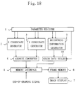
- FIG 18 illustrates a configuration for a line-drawing apparatus of the third embodiment.
- this apparatus further includes brightness information generator 9 and color data scaler 10 between the parameter register 1 and the memory interface 5 .
- the brightness information generator 9 has a similar configuration to that of the X and Y coordinate generators 2 and 3 .
- the color data scaler 10 receives the output of the brightness information generator 9 , performs color data scaling with reference to the brightness data and then outputs the scaled information to the memory interface 5 .
- the line-drawing apparatus of the third embodiment can perform brightness interpolation on a line connecting start and end points where brightness (or luminance) information is added to the coordinate data representing the line including the start and end points.
- the X and Y coordinates of the start and end point coordinate data are input to the X and Y coordinate generators 2 and 3 .
- the operation is performed a predetermined number of times to obtain the coordinate data representing the first, second, third midpoints and so on, which are subsequently output to the address converter 4 .
- the brightness data values of the start and end point coordinate data are input to the brightness information generator 9 .
- the brightness information generator 9 adds together the numerical values representing the brightness of the start and end points and divides the sum by two, thereby outputting a piece of brightness interpolation information.
- the brightness information generator 9 may have the same configuration as the X coordinate generator 2 shown in Figure 2 . That is to say, in this case, the first and second FIFO memories 11 and 12 , adder 21 and shifter 22 function as first and second brightness data storage means, brightness data adding means and brightness data divide-by-two means, respectively.
- the brightness data generated is input to the color data scaler 10 , which performs color data scaling with reference to the brightness data.
- the scaling is performed by regarding brightness values 0 and 1 as representing relatively dark and relatively bright colors, respectively. Accordingly, if a line to be drawn has start and end points with respective brightness values 0 and 1, then the brightness of its midpoint will calculate as 0.5. By integrating this value with the color data, brightness-indexed color data can be obtained.
- the brightness-indexed color interpolation information which has been generated by the color data scaler 10 , is combined with its associated coordinate data in the frame memory 6 . Then, a pixel in the specified color and with the specified brightness is drawn on the image display 7 .
- the apparatus uses no dividers, which are usually needed in a conventional apparatus and adversely increase the computational costs, even in drawing a short line that should be provided with some gradation in accordance with brightness-indexed color information.
- the apparatus can draw such a line at a higher speed with its hardware configuration simplified.
- a single piece of color information is associated with multiple brightness data values.
- those brightness data values may be defined for each of the three primary colors as in the modified example of the second embodiment.
- the brightness information generator 9 and the color data scaler 10 of the third embodiment may also be added to the line-drawing apparatus of the second embodiment.
- the line-drawing apparatus can perform both brightness and color interpolations in drawing a line.
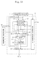
- Figure 19 illustrates a detailed configuration for an X coordinate generator in a line-drawing apparatus of the fourth embodiment.
- the same components as those illustrated in Figure 2 will be identified by the same reference numerals and the description thereof will be omitted herein.
- the line-drawing apparatus is adapted to draw a short line as a collection of points within a predetermined amount of time.
- the line-drawing apparatus of the fourth embodiment takes advantage of the conventional method of calculating a linear parameter representing the slope of a line to be drawn.
- the line-drawing apparatus of this embodiment selectively adopts the method of generating multiple midpoints successively or the conventional method of calculating the linear parameter depending on the longer-side value (i.e., the number of pixels).
- the line-drawing apparatus further includes a parameter calculator 41 .
- the parameter calculator 41 receives the start and end point coordinate data from the parameter register 1 , calculates the slope of a line including the start and end points represented by the coordinate data received and then outputs the slope to the X coordinate calculator 13 .
- the X coordinate generator 2 further includes first, second and third selectors 42 , 43 and 44 implemented as the first, second and third selecting means as defined in the appended claims.
- the first selector 42 receives the output values of the first FIFO memory 11 and the parameter calculator 41 and selectively outputs one of these values to the X coordinate calculator 13 .
- the second selector 43 receives the output values of the second FIFO memory 12 and the X coordinate calculator 13 and selectively outputs one of these values to the X coordinate calculator 13 .
- the third selector 44 receives the respective output values of the parameter register 1 , adder 21 and shifter 22 and selectively outputs one of these values to the address converter 4 .
- Figure 20 illustrates a detailed configuration for an iterative number regulator 25 in the X coordinate controller 14 according to the fourth embodiment.
- the iterative number regulator 25 further includes a line-drawing method determiner 25d .
- the line-drawing method determiner 25d receives the output of the longer side calculator/selector 25a and determines whether or not the absolute value of the difference between X or Y coordinates of the start and midpoint coordinate data exceeds a predetermined value. If the absolute value is greater than the predetermined value, then the line-drawing method determiner 25d generates and outputs a line-drawing method determination signal to the first and second selectors 42 and 43 such that the output of the parameter calculator 41 is selected.
- the line-drawing apparatus In drawing a short line, the line-drawing apparatus operates just as described in the first embodiment. On the other hand, in drawing a long line, the line-drawing apparatus adopts the conventional line-drawing method. Thus, it will be mainly described with reference to the processing flow shown in Figure 21 how the iterative number regulator 25 shown in Figure 20 determines which of the long and short line drawing methods should be taken.
- Figure 21 is a flowchart illustrating how the iterative number regulator 25 determines the line-drawing method to take according to the fourth embodiment.
- the longer side calculator/selector 25a performs a longer side calculation and selection process shown in Figure 21 . Specifically, supposing the coordinate data representing the start and end points to be drawn are (Xs, Ys) and (Xe, Ye), respectively, the longer side calculator/selector 25 obtains the respective absolute values of the difference between the X coordinates (
- the line-drawing method determiner 25d determines whether or not the absolute value, output from the longer side calculator/selector 25a , is greater than a predetermined longer-side value (or the predetermined number of pixels). Suppose the absolute value is greater than a longer-side value of 9, for example. In such a case, the determiner 25d makes the first selector 42 select the output signal of the parameter calculator 41 and makes the second selector 43 select the output signal of the X coordinate calculator 13 . And the determiner 25d outputs a line-drawing method determination signal, which disables the output signal of the shifter 22 , to the third selector 44 .
- the determiner 25d makes the first and second selectors 42 and 43 select the output signals of the first and second FIFO memories 11 and 12 , respectively. And the determiner 25d outputs a line-drawing method determination signal, which disables the output signal of the adder 21 , to the third selector 44 .
- the number-of-times comparator 25b shown in Figure 20 determines, based on the data provided from the longer side calculator/selector 25a , how many times the operation should be performed. Supposing the iterative number determination table shown in Table 2 is used, if the number of pixels is three or less, then the operation should be performed just once as shown in Figure 21 . Using the same table, the operation will be performed three and seven times, respectively, for five pixels or less and nine pixels or less, respectively.
- the line-drawing method determiner 25d may also be connected to receive the output of the number-of-times comparator 25b . In such an embodiment, there is no need to perform the process of determining whether the output of the longer side calculator/selector 25a exceeds a predetermined value such that the long line drawing method is adopted for nine pixels or more.
- the line-drawing apparatus of the fourth embodiment can generate coordinates for any line using the same computational resource, i.e., the adder 21 in this case, no matter whether the line to be drawn is long or short. Thus, even when short and long lines both should be drawn, a hardware resource can be shared without providing any additional adder 8 .
- the "short line” is supposed to correspond to nine pixels or less.
- the present invention is not limited to this specific value.
- the number of FIFO stages is four in the foregoing embodiments, the number does not have to be four. Instead, as can be seen from the relationship shown in Table 1 between the number of FIFO stages and the longer-side value, any other appropriate number may be selected for a line to be drawn.
- the conventional line-drawing method using a linear parameter is adopted to draw a long line.
- the long line to be drawn is once divided into a plurality of short lines and then those short lines divided are drawn one after another.
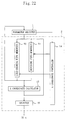
- Figure 22 illustrates a configuration for an X coordinate generator 2 for the line-drawing apparatus of the fifth embodiment.
- the same components as those of the X coordinate generator 2 of the first embodiment shown in Figure 2 are identified by the same reference numerals and the description thereof will be omitted herein.
- the X coordinate generator 2 of the fifth embodiment includes line-drawing FIFO memories 50 and dividing FIFO memories 51 .
- the line-drawing FIFO memories 50 include the first and second FIFO memories 11 and 12 shown in Figure 2 .
- the dividing FIFO memories 51 are connected in parallel to the line-drawing FIFO memories 50 and include memories with a function equivalent to that of the first and second FIFO memories 11 and 12 .
- the dividing FIFO memories 51 are also provided for the Y coordinate generator.
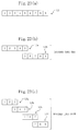
- Figure 23(a) illustrates a long line L1 to be drawn with a longer-side value of 9.
- Table 1 if the number of FIFO stages of each of the line-drawing FIFO memories 50 is four, then the longer-side value of the long line to be drawn is 5.
- the dividing FIFO memories 51 divide this long line L1 into two, thereby generating first and second short lines L2a and L2b as shown in Figure 23(b) .
- the first short line L2a starts at "1" and ends at "5"
- the second short line L2b starts at "5" and ends at "9".
- the dividing FIFO memories 51 divide the long line L1 into four, thereby generating first, second, third and fourth short lines L3a , L3b , L3c and L3d as shown in Figure 23(c) .
- the first short line L3a starts at "1" and ends at "3”
- the second short line L3b starts at "3" and ends at "5"
- the third short line L3c starts at "5" and ends at "7”
- the fourth short line L3d starts at "7" and ends at "9".
- Table 3 is an example of a more practical division number determination table: Longer-side value Division Number Number of times of Divide-by-two operation 3 through 33 1 0 34 through 65 2 1 66 through 129 4 3 130 through 257 8 7
- Figure 24 illustrates a configuration for a number-of-times comparator 25b including the division number determination table.
- the same components as those illustrated in Figure 6 are identified by the same reference numerals.
- the number-of-times comparator 25b of the fifth embodiment includes line-drawing ROM table 251A and dividing ROM table 251B .
- the line-drawing ROM table 251A is used for determining the number of times the line-drawing operation should be performed to draw short lines.
- the dividing ROM table 251B is used for determining the number of times the divide-by-two operation should be performed to divide the long line into short lines.
- a long line is repeatedly divided in advance into short lines by the same method as that used to draw a short line until each of the short lines can be drawn. And then these short lines divided are drawn one after another. Accordingly, even a long line with a longer-side value exceeding that determined by the number of FIFO stages of the dividing FIFO memories 51 can be drawn without using the linear parameters.
- the long line L1 is divided at its midpoint as is done in each embodiment of the present invention.
- multiple line-drawing apparatuses of the first embodiment may be prepared. In that case, after a long line to be drawn has been divided into a plurality of short lines that can be drawn by these apparatuses, those short lines may be drawn by the same number of line-drawing apparatuses in parallel. In this manner, the long line can be drawn in a much shorter time.
- the conventional method of drawing a line using its linear parameter may be additionally adopted as in the fourth embodiment.
Landscapes
- Physics & Mathematics (AREA)
- General Physics & Mathematics (AREA)
- Engineering & Computer Science (AREA)
- Theoretical Computer Science (AREA)
- Image Generation (AREA)
- Digital Computer Display Output (AREA)
Abstract
Description
| Index (Id) | Number of FIFO Stages (2id+1) | Longer-side Value (n=2(id+1)+1 | Number of Times of Operation (n-2) |
| 0 | 2 | 3 | 1 |
| 1 | 4 | 5 | 3 |
| 2 | 8 | 9 | 7 |
| 3 | 16 | 17 | 15 |
| 4 | 32 | 33 | 31 |
| 5 | 64 | 65 | 63 |
| Longer-Side Value | Number of times of Operation |
| 1(0001) | 1 |
| 2(0010) | 1 |
| 3(0011) | 1 |
| 4(0100) | 3 |
| 5(0101) | 3 |
| 6(0110) | 7 |
| 7(0111) | 7 |
| 8(1000) | 7 |
| 9(1001) | 7 |
| Longer-side value | Division Number | Number of times of Divide-by-two |
| 3 through 33 | 1 | 0 |
| 34 through 65 | 2 | 1 |
| 66 through 129 | 4 | 3 |
| 130 through 257 | 8 | 7 |
Claims (13)
- An apparatus for drawing a line connecting a start point to an end point, the start and end points being represented by mutually different sets of coordinates, the apparatus comprising:midpoint coordinate generating means for generating coordinates for first, second and third midpoints, the first midpoint being located in the middle of a line segment connecting the start and end points together, the second midpoint being located in the middle of a line segment connecting the start point and the first midpoint together, the third midpoint being located in the middle of a line segment connecting the end point and the first midpoint together; anddisplay means for presenting the start point, the first, second and third midpoints and the end point thereon.
- The apparatus of Claim 1, wherein the midpoint coordinate generating means further generates coordinates for other midpoints, each of the other midpoints being located in the middle of a line segment ending at two adjacent ones of the points.
- The apparatus of Claim 1, wherein the line connecting the start and end points together is divided into a number 2n of line segments, where n is an integer equal to or greater than zero, and
wherein each said line segment is further divided by two with the line segment regarded as ending at a new pair of start and end points. - The apparatus of Claim 3, wherein at least one midpoint is obtained by dividing the line connecting the start and end points together into a number 2n of line segments, where n is an integer greater than zero, and
wherein each said midpoint obtained is located in the middle of a line segment connecting two of the other points, where one of the two points is located closer to the start point while the other is located closer to the end point. - An apparatus for drawing a line connecting a start point to an end point, the start and end points both being presented on display means and being represented by mutually different sets of coordinates, the apparatus comprising:first and second data storage means, each said storage means accepting a plurality of input coordinate data and sequentially outputting one item of these data after another on a first in, first out basis;adding means for receiving and adding together the respective coordinate data output from the first and second data storage means and outputting added data; anddivide-by-two means for dividing the added data by two and outputting divided data,
wherein the coordinate data output from the first and second data storage means are input to the first data storage means, and
wherein the divided data is input from the divide-by-two means to the second storage means, and
wherein the line connecting the start and end points together is drawn on the display means in accordance with the divided data output from the divide-by-two means. - The apparatus of Claim 5, wherein the divide-by-two means is a shifter that is so interconnected as to shift the added data to the right by one bit.
- The apparatus of Claim 5, further comprising iteration control means for regulating the number of times the output data is fed back to the first and second storage means,
wherein the iteration control means includes:a longer side calculator/selector for calculating respective absolute values of a difference between X coordinates and a difference between Y coordinates of the start and end points and for outputting one of these two differences that has the greater absolute value; anda number-of-times comparator for determining, by the absolute value, the number of times the output should be fed back. - The apparatus of Claim 5, further comprising:first and second color data storage means, each said color data storage means accepting a plurality of input color data and sequentially outputting one of the data after another on a first in, first out basis;color data adding means for receiving and adding together the respective color data output from the first and second color data storage means and outputting added color data; andcolor data divide-by-two means for dividing the added color data by two and outputting divided color data,
wherein the color data, which are output from the first and second color data storage means and correspond to the start and end points, respectively, are input to the first color data storage means, and
wherein the divided color data, output from the color data divide-by-two means, is input to the second color data storage means, and
wherein the color of the line connecting the start and end points together is determined in accordance with the divided color data. - The apparatus of Claim 5, further comprising:first and second brightness data storage means, each said brightness data storage means accepting a plurality of input brightness data and sequentially outputting one of the data after another on a first in, first out basis;brightness data adding means for receiving and adding together the respective brightness data output from the first and second brightness data storage means and outputting added brightness data; andbrightness data divide-by-two means for dividing the added brightness data by two and outputting divided brightness data,
wherein the brightness data, which are output from the first and second brightness data storage means and correspond to the start and end points, respectively, are input to the first brightness data storage means, and
wherein the divided brightness data, output from the brightness data divide-by-two means, is input to the second brightness data storage means, and
wherein the brightness of the line connecting the start and end points together is determined in accordance with the divided brightness data. - The apparatus of Claim 5, further comprising:linear parameter calculating means for calculating and outputting a linear parameter representing a slope of the line connecting the start and end points together;first selecting means for receiving the linear parameter and the output data of the first data storage means and selectively outputting either the parameter or the output data of the first data storage means to the adding means; andsecond selecting means for receiving the divided data and the output data of the second data storage means and selectively outputting either the divided data or the output data of the second data storage means to the adding means.
- An apparatus for drawing a line connecting a start point to an end point, the start and end points both being presented on display means and being represented by mutually different sets of coordinates, the apparatus comprising:data storage means with data storage areas on which multiple coordinate data are storable, the coordinate data including first and second coordinate data of the line connecting the start and end points together;adding means for adding together the first and second coordinate data and outputting added data; anddivide-by-two means for dividing the added data by two and outputting divided data,
wherein the divided data is stored as third coordinate data on a predetermined one of the data storage areas. - The apparatus of Claim 11, wherein the adding and divide-by- two means repeatedly perform the addition and the divide-by-two operation for multiple line segments a number of times determined by the number of the data storage areas, each said line segment ending at two adjacent ones of midpoints that correspond to the respective coordinate data, results of the addition and the divide-by-two operation being stored on respectively predetermined ones of the data storage areas.
- A method for drawing a line connecting a start point to an end point using a line-drawing apparatus, the apparatus including: display means; first and second data storage means of a first in, first out type; adding means for receiving outputs of the first and second data storage means; and divide-by-two means for dividing an output of the adding means by two, the start and end points both being presented on the display means and being represented by mutually different sets of coordinates,the method comprising the steps of:a) outputting start and end point coordinate data, which represent the start and end points, respectively, to the display means;b) storing the start and end point coordinate data in the first and second data storage means, respectively;c) outputting the start point coordinate data from the first data storage means to the adding means and storing the start point coordinate data back to the first storage means concurrently;d) outputting the end point coordinate data from the second data storage means to the adding means and storing the end point coordinate data on the first storage means concurrently;e) outputting a sum of the start and end point coordinate data from the adding means to the divide-by-two means; andf) providing output data of the divide-by-two means to the display means and storing the output data of the divide-by-two means on the second data storage means concurrently such that the output data of the divide-by-two means corresponds to the start and end point coordinate data stored in the steps c) and d).
Applications Claiming Priority (2)
| Application Number | Priority Date | Filing Date | Title |
|---|---|---|---|
| JP28403199 | 1999-10-05 | ||
| JP28403199 | 1999-10-05 |
Publications (2)
| Publication Number | Publication Date |
|---|---|
| EP1091321A2 true EP1091321A2 (en) | 2001-04-11 |
| EP1091321A3 EP1091321A3 (en) | 2002-09-25 |
Family
ID=17673417
Family Applications (1)
| Application Number | Title | Priority Date | Filing Date |
|---|---|---|---|
| EP00121797A Withdrawn EP1091321A3 (en) | 1999-10-05 | 2000-10-05 | Apparatus and method for drawing lines on a digital display |
Country Status (2)
| Country | Link |
|---|---|
| US (1) | US6859205B1 (en) |
| EP (1) | EP1091321A3 (en) |
Families Citing this family (3)
| Publication number | Priority date | Publication date | Assignee | Title |
|---|---|---|---|---|
| JP2008009719A (en) * | 2006-06-29 | 2008-01-17 | Fujitsu Ltd | Line drawing method, line drawing program, and line drawing apparatus |
| CN101334985B (en) * | 2007-06-27 | 2012-02-01 | 深圳迈瑞生物医疗电子股份有限公司 | Wave data displaying apparatus and method |
| US9064459B2 (en) * | 2007-06-29 | 2015-06-23 | Samsung Electronics Co., Ltd. | Display apparatus and brightness adjusting method thereof |
Family Cites Families (9)
| Publication number | Priority date | Publication date | Assignee | Title |
|---|---|---|---|---|
| EP0247711A3 (en) | 1986-05-30 | 1989-08-09 | Prime Computer, Inc. | Line display apparatus and method |
| US5167015A (en) | 1988-06-13 | 1992-11-24 | Industrial Technology Research Institute | Line drawing method and apparatus |
| US5214754A (en) | 1988-06-29 | 1993-05-25 | Fujitsu Limited | Method and apparatus for approximating polygonal line to curve |
| JPH0561979A (en) | 1991-08-30 | 1993-03-12 | Mitsubishi Heavy Ind Ltd | Fast plotting system in parallel processing |
| JPH05346936A (en) | 1992-06-15 | 1993-12-27 | Daikin Ind Ltd | Linear interpolation method and apparatus thereof |
| US5594848A (en) * | 1993-02-16 | 1997-01-14 | Compaq Computer Corporation | Method and apparatus for efficiently determining line segments within a window using iterative halving |
| JP2778525B2 (en) | 1995-05-31 | 1998-07-23 | 日本電気株式会社 | Polygon figure shaping device |
| US5969699A (en) * | 1996-10-08 | 1999-10-19 | Kaiser Aerospace & Electronics Company | Stroke-to-stroke |
| US5841442A (en) | 1996-12-30 | 1998-11-24 | Cirrus Logic, Inc. | Method for computing parameters used in a non-homogeneous second order perspective texture mapping process using interpolation |
-
2000
- 2000-10-03 US US09/677,821 patent/US6859205B1/en not_active Expired - Fee Related
- 2000-10-05 EP EP00121797A patent/EP1091321A3/en not_active Withdrawn
Also Published As
| Publication number | Publication date |
|---|---|
| EP1091321A3 (en) | 2002-09-25 |
| US6859205B1 (en) | 2005-02-22 |
Similar Documents
| Publication | Publication Date | Title |
|---|---|---|
| US8194098B2 (en) | Apparatus, method, and product for downscaling an image | |
| US6246421B1 (en) | Apparatus and method for parallel rendering of image pixels | |
| US6181353B1 (en) | On-screen display device using horizontal scan line memories | |
| EP0336776A2 (en) | Image magnification | |
| CA2743039A1 (en) | Bezier curve drawing device, bezier curve drawing method, and recording medium | |
| US20050068338A1 (en) | Method and system for scaling images | |
| US5604852A (en) | Method and apparatus for displaying a parametric curve on a video display | |
| US4608660A (en) | Data processing system with condition data setting function | |
| JPH11283015A (en) | Picture color mixing processor | |
| EP0301253B1 (en) | Line generation in a display system | |
| JPH0927039A (en) | Method and apparatus for calculating texel values for displaying texture on an object | |
| US6859205B1 (en) | Apparatus and method for drawing lines | |
| EP0574245A2 (en) | Method and apparatus for variable expansion and variable shrinkage of an image | |
| GB2226481A (en) | Method and apparatus for decomposing a quadrilateral figure for display and manipulation by a computer system | |
| US5815163A (en) | Method and apparatus to draw line slices during calculation | |
| US20050225802A1 (en) | Image processing apparatus and method and program of the same | |
| US6005988A (en) | Method and apparatus for rapid digital image resizing | |
| US5627956A (en) | Run slice line draw engine with stretching capabilities | |
| JP3593016B2 (en) | Straight line drawing device, straight line drawing method, and coordinate generation device | |
| US5617524A (en) | Run slice line draw engine with shading capabilities | |
| US4945497A (en) | Method and apparatus for translating rectilinear information into scan line information for display by a computer system | |
| US5611029A (en) | Run slice line draw engine with non-linear shading capabilities | |
| US5714986A (en) | Run slice line draw engine with enhanced line configurations | |
| US5657435A (en) | Run slice line draw engine with non-linear scaling capabilities | |
| US5600769A (en) | Run slice line draw engine with enhanced clipping techniques |
Legal Events
| Date | Code | Title | Description |
|---|---|---|---|
| PUAI | Public reference made under article 153(3) epc to a published international application that has entered the european phase |
Free format text: ORIGINAL CODE: 0009012 |
|
| AK | Designated contracting states |
Kind code of ref document: A2 Designated state(s): AT BE CH CY DE DK ES FI FR GB GR IE IT LI LU MC NL PT SE |
|
| AX | Request for extension of the european patent |
Free format text: AL;LT;LV;MK;RO;SI |
|
| PUAL | Search report despatched |
Free format text: ORIGINAL CODE: 0009013 |
|
| AK | Designated contracting states |
Kind code of ref document: A3 Designated state(s): AT BE CH CY DE DK ES FI FR GB GR IE IT LI LU MC NL PT SE |
|
| AX | Request for extension of the european patent |
Free format text: AL;LT;LV;MK;RO;SI |
|
| 17P | Request for examination filed |
Effective date: 20030313 |
|
| AKX | Designation fees paid |
Designated state(s): DE FR GB |
|
| 17Q | First examination report despatched |
Effective date: 20030603 |
|
| RAP1 | Party data changed (applicant data changed or rights of an application transferred) |
Owner name: PANASONIC CORPORATION |
|
| STAA | Information on the status of an ep patent application or granted ep patent |
Free format text: STATUS: THE APPLICATION IS DEEMED TO BE WITHDRAWN |
|
| 18D | Application deemed to be withdrawn |
Effective date: 20100501 |