EP1091156A2 - Improvements in or relating to fluid seals - Google Patents
Improvements in or relating to fluid seals Download PDFInfo
- Publication number
- EP1091156A2 EP1091156A2 EP00308711A EP00308711A EP1091156A2 EP 1091156 A2 EP1091156 A2 EP 1091156A2 EP 00308711 A EP00308711 A EP 00308711A EP 00308711 A EP00308711 A EP 00308711A EP 1091156 A2 EP1091156 A2 EP 1091156A2
- Authority
- EP
- European Patent Office
- Prior art keywords
- seal
- filter
- hole
- fluid
- assembly
- Prior art date
- Legal status (The legal status is an assumption and is not a legal conclusion. Google has not performed a legal analysis and makes no representation as to the accuracy of the status listed.)
- Withdrawn
Links
Images


Classifications
-
- F—MECHANICAL ENGINEERING; LIGHTING; HEATING; WEAPONS; BLASTING
- F16—ENGINEERING ELEMENTS AND UNITS; GENERAL MEASURES FOR PRODUCING AND MAINTAINING EFFECTIVE FUNCTIONING OF MACHINES OR INSTALLATIONS; THERMAL INSULATION IN GENERAL
- F16L—PIPES; JOINTS OR FITTINGS FOR PIPES; SUPPORTS FOR PIPES, CABLES OR PROTECTIVE TUBING; MEANS FOR THERMAL INSULATION IN GENERAL
- F16L19/00—Joints in which sealing surfaces are pressed together by means of a member, e.g. a swivel nut, screwed on or into one of the joint parts
- F16L19/02—Pipe ends provided with collars or flanges, integral with the pipe or not, pressed together by a screwed member
- F16L19/0212—Pipe ends provided with collars or flanges, integral with the pipe or not, pressed together by a screwed member using specially adapted sealing means
-
- F—MECHANICAL ENGINEERING; LIGHTING; HEATING; WEAPONS; BLASTING
- F16—ENGINEERING ELEMENTS AND UNITS; GENERAL MEASURES FOR PRODUCING AND MAINTAINING EFFECTIVE FUNCTIONING OF MACHINES OR INSTALLATIONS; THERMAL INSULATION IN GENERAL
- F16L—PIPES; JOINTS OR FITTINGS FOR PIPES; SUPPORTS FOR PIPES, CABLES OR PROTECTIVE TUBING; MEANS FOR THERMAL INSULATION IN GENERAL
- F16L23/00—Flanged joints
- F16L23/16—Flanged joints characterised by the sealing means
- F16L23/18—Flanged joints characterised by the sealing means the sealing means being rings
-
- Y—GENERAL TAGGING OF NEW TECHNOLOGICAL DEVELOPMENTS; GENERAL TAGGING OF CROSS-SECTIONAL TECHNOLOGIES SPANNING OVER SEVERAL SECTIONS OF THE IPC; TECHNICAL SUBJECTS COVERED BY FORMER USPC CROSS-REFERENCE ART COLLECTIONS [XRACs] AND DIGESTS
- Y10—TECHNICAL SUBJECTS COVERED BY FORMER USPC
- Y10S—TECHNICAL SUBJECTS COVERED BY FORMER USPC CROSS-REFERENCE ART COLLECTIONS [XRACs] AND DIGESTS
- Y10S277/00—Seal for a joint or juncture
- Y10S277/918—Seal combined with filter or fluid separator
Abstract
Description
- This invention concerns improvements in or relating to fluid seals. The invention has particular, but not exclusive application to fluid seals for sealing joints between two components connected together in a fluid line, for example between two pipes, or between a pipe and another fitting or between two fittings such as a hydraulic block to which one or more parts may be attached, for example a pump or valve application.
- It is already well known in the water and automotive industries to provide sealing rings for sealing joints between two components in a fluid line. The sealing rings may be made of rubber or plastics compatible with the fluid to be transmitted in the fluid line, for example water, oil, petrol, solvents.
- For many applications, it is desirable to remove any solid particles present in the fluid to prevent damage to equipment connected to the fluid line. For this purpose, it is common to fit a filter in the fluid line, for example a metal or plastics mesh screen having a mesh rating to remove solid particles above a given size.
- For convenience, the mesh screen may be fitted at a joint between two components in the fluid line. This can complicate the provision of an adequate seal. In addition, fitting separate seal and filter elements adds to material costs and installation costs. Also, there is a risk of joints being assembled without the filter resulting in damage to equipment connected in the fluid line.
- Accordingly, the present invention seeks to provide an arrangement whereby the seal and filter are combined in a single component for installation in a fluid line.
- It is a preferred object of the present invention to provide an arrangement in which a peripheral edge region of the filter is embedded in the seal, and the seal is compressible on either side of the filter between opposed surfaces of relatively axially movable components to effect a fluid tight seal between the components.
- It is another preferred object of the present invention to provide an arrangement in which compression of the seal is controlled so as to maintain integrity of the seal and filter.
- It is a further preferred object of the present invention to provide an assembly including an adaptor so constructed that fitment and installation of the seal and filter in a fluid line can be effected in a simple and effective manner which preferably also allows access to the filter for cleaning, repair or replacement during routine maintenance and/or in an emergency.
- It is yet another preferred object of the present invention to provide such assembly in which the seal and filter are located with the filter in a desired orientation, preferably transverse, to the fluid line in which the adaptor is installed.
- According to a first aspect, the present invention provides a solution to the problems and disadvantages aforementioned by providing an integral seal and filter assembly capable of sealing a joint between two components in a fluid line and filtering fluid in the fluid line. In this way, by combining the seal and filter in a single unitary construction the supply and installation of separate seal and filter elements is avoided.
- The combined seal and filter can be of any size and shape to suit a given application, for example circular, oval, rectangular, or other polygonal shape. As will be appreciated, by providing an integral seal and filter, the filter can be made to any shape and the seal configured to this shape by attaching to the filter. In this way, both simple and complex seal shapes can be produced and maintained for any desired application.
- Preferably, the seal is bonded to the peripheral edge of the filter. For example, the filter may comprise a mesh screen with the peripheral edge embedded in the seal. In this way, the material of the seal penetrates the interstices of the mesh so as to become mechanically bonded through the mesh.
- The mesh screen may be made of metal, for example stainless steel, aluminium or brass. Alternatively, the mesh screen may be made of plastics. The mesh can be of any size for the filter rating required for a particular application.
- The seal may be made of elastomer, for example rubber such as nitrile rubber, hydrogenated nitrile rubber, ethylene propylene diene monomer, fluorocarbons, polyacrylic, neoprene, fluorosilicon, or other suitable compounds for the intended application. Alternatively, the seal may be made of plastics. The seal material is chosen to be compatible with the fluid in the fluid line.
- Advantageously, the mesh is provided with a barrier spaced from the peripheral edge to restrict flow of the seal material from the peripheral edge region towards the centre region of the mesh. In this way, only the peripheral edge region is embedded in the seal material and the centre region is left free to provide the filtering function.
- The mesh may be woven and the barrier formed by crushing a narrow region of the mesh inwardly of the peripheral edge prior to or during moulding of the seal to form a crease separating the edge region of the mesh from the centre region to prevent the seal material penetrating the centre region of the filter. This is found to be particularly suitable for woven meshes having a mesh size of up to 200 microns.
- Alternatively, the mesh may be produced by photochemical machining an array of perforations in a pre-form and the barrier formed by masking the pre-form to produce a region free from perforations separating the edge region of the mesh from the centre region to prevent the seal material penetrating the centre region of the filter. This is found to be particularly suitable for photofabrication of meshes having a mesh size of more than 200 microns, especially 300 to 400 microns.
- Preferably, the seal is formed with a plurality of outwardly projecting lobes spaced apart around the outer edge of the seal and substantially co-planar with the seal and filter. The lobes facilitate moulding the seal onto the filter by allowing the seal material to pass from one side to the other around the outer edge of the filter within the mould. The lobes also act as spacers to centre the seal and filter assembly for installation in a fluid line, for example in a counterbore of a component forming part of the fluid line.
- Advantageously, the seal has a sealing portion of generally trapezoidal cross-section with a maximum axial dimension at the inner edge of the seal and sealing surfaces that extend from the inner edge and converge towards each other. In this way, the inner edge of the seal has a substantially planar sectional shape in the undeformed condition of the seal and a substantially concave sectional shape when compressed. As a result, compression of the seal can be accommodated without adversely affecting the integrity of the seal and filter.
- The filter provides a degree of reinforcement for the seal which is generally sufficient for most applications of the seal and filter assembly involving low fluid pressures but, at high fluid pressures, for example up to 200 bar, the seal and filter assembly is preferably provided with additional reinforcement. Such reinforcement conveniently takes the form of an outer support member, for example a plate, to which the seal is bonded to form a unitary construction.
- Advantageously, the plate has a hole with a counterbore providing a shoulder for locating the peripheral edge of the filter with the seal encapsulating the peripheral edge and bonded to the marginal edge of the hole.
- Preferably, the seal projects outwardly from the plate on both sides for sealing engagement with the components of the joint to be sealed. The plate may act as a spacer to limit the compression of the seal. The plate may be made of metal, for example zinc plated steel or stainless steel. Alternatively, the plate may be made of plastics, for example polycarbonate.
- According to a second aspect, the present invention provides a method of forming a seal and filter assembly comprising providing a filter and bonding a seal to the marginal edge of the filter.
- Preferably, the seal is confined to the marginal edge of the filter by providing the filter with a barrier prior to or during moulding of the seal onto the filter.
- Advantageously, the seal is bonded to the marginal edge of a hole in an outer support member which may act as a spacer to control compression of the seal.
- Preferably, the seal has a sealing portion of trapezoidal section inwardly of the hole with sealing surfaces projecting from the support member on each side and convergent from an inner edge of the seal towards the support member.
- According to a third aspect, the present invention provides a method of forming a fluid tight joint between first and second components in a fluid line comprising providing an integral seal and filter element, positioning the element with the seal between opposed faces of the first and components and the filter extending across the fluid line, and relatively moving the first and second components in an axial direction to compress the seal between the opposed faces on each side of the filter.
- The two components may be pipes having opposed end flanges with the seal arranged between the flanges so as to be compressed when the flanges are urged axially towards each other to provide a fluid tight joint for liquid and/or gas. One of the flanges may have a recess in the end face in which the seal is positioned to limit compression of the seal. Alternatively, one of the components may be a pipe and the other component a fitting to which the pipe is attached. Other arrangements are possible, for example a block for one or more fluid lines to which fittings are attached, for example a pump or valve, with the seal arranged between the block and the fitting.
- In a preferred arrangement, the components comprise first and second threadably engageable parts of an adaptor defining a passageway for flow of fluid through the adaptor wherein the seal is disposed between opposed abutment faces of the first and second parts, and the filter is located transverse to the passageway.
- According to a fourth aspect, the present invention provides an assembly for mounting in a fluid line, the assembly including an adaptor having first and second parts releasably connectable to define a passageway for flow of fluid therethrough, a filter, and a seal integral with a marginal edge of the filter, the seal being arranged to contact opposed abutment faces of the first and second parts on each side of the filter and being compressed therebetween when the first and second parts are connected to seal the filter in the adaptor with the filter extending across the passageway.
- Preferably, the first and second parts have co-operating screw threads arranged for relative axial movement of the first and second parts to urge the abutment faces axially towards each other to compress the seal therebetween in the assembled adaptor. In a preferred arrangement, the first and second parts are provided with complementary internal and external screw threads on a socket portion of a female fitting and a plug portion of a male fitting.
- Advantageously, one of the abutment faces is provided by the recess in which the filter and seal are located and retained in the assembled adaptor so that the filter is positioned transverse to the passageway. In this way, compression of the seal may be controlled by the depth of the recess.
- Preferably, the filter and seal are mounted in a support member, such as a plate, which is received in the recess and is preferably arranged to limit compression of the seal between the abutment faces when the parts are tightened during assembly of the adaptor. For example, the depth of the recess may be less than the thickness of the support member so that the support member projects from the recess and is clamped between the abutment faces in the assembled adaptor.
- Advantageously, the support member has a hole with a counterbore providing a shoulder for locating the peripheral edge of the filter with the seal encapsulating the peripheral edge and bonded to the marginal edge of the hole.
- Preferably, the support member has a plurality of notches formed in the marginal edge of the hole and projecting beyond the outer edge of the filter to allow the seal material to pass around the outer edge of the filter and form a plurality of lobes spaced part around the outer edge of the seal.
- Advantageously, the support member has generally parallel upper and lower surfaces and the seal has an inner portion that projects from the upper and lower surfaces of the support member and an outer portion substantially co-planar with or set back from the upper and lower surfaces of the support member. In a preferred construction, the inner portion is of generally trapezoidal section having a wider end at the inner edge and sealing surfaces converging to a narrower end at or adjacent to the support member.
- Other features, benefits and advantages of the invention will be apparent to those skilled in the art from the description hereinafter illustrating, without limitation or restriction, various aspects of the invention.
- Exemplary embodiments of the invention will now be described with reference to the accompanying drawings wherein:-
- Figure 1 is an end view of a combined seal and filter according to a first embodiment of the invention;
- Figure 2 is a section of a joint incorporating the seal and filter of Figure 1;
- Figure 3 is a section of an alternative joint incorporating the seal and filter of Figure 1;
- Figure 4 is an end view of a combined seal and filter according to a second embodiment of the invention;
- Figure 5 is a section on the line 5-5 of Figure 4;
- Figure 6 is an end view of the support member shown in Figures 4 and 5;
- Figure 7 is a section of a joint similar to Figure 2 incorporating the seal and filter of Figures 4 and 5;
- Figure 8 is a section of a joint similar to Figure 3 incorporating the seal and filter of Figures 4 and 5;
- Figure 9 is an exploded longitudinal sectional view of an adaptor assembly including the second embodiment of seal and filter shown in Figures 4 to 6;
- Figure 10 is a longitudinal sectional view of the assembled adaptor assembly of Figure 9;
- Figure 11 is an end view of the adaptor shown in Figures 9 and 10;
- Figure 12 is an end view of a combined seal and filter according to a third embodiment of the invention;
- Figure 13 is a section on the line 13-13 of Figure 12;
- Figure 14 is a section on the line 14-14 of Figure 12;
- Figure 15 is an end view of a twin seal and filter arrangement according to a fourth embodiment of the invention; and
- Figure 16 is a section on the line 16-16 of Figure 15.
-
- In the following description of exemplary embodiments of the invention, like reference numerals are used throughout to indicate the same or similar parts in each embodiment.
- Referring first to Figure 1, there is shown a first embodiment of combined seal 1 and
filter 2 comprising aseal ring 3 and awire mesh screen 4. - The
seal ring 3 is made of rubber or any other suitable elastomer for the intended application moulded directly onto the peripheral edge region of thescreen 4. In this embodiment, theseal ring 3 is an O-ring of circular cross-section but this is not essential and other cross-sections may be employed, for example oval, rectangular, trapezoidal. - The
screen 4 is made of metal, for example stainless steel or brass, and has a mesh size for the intended application. Thescreen 4 is embedded around the peripheral edge region in the elastomer of theseal ring 3 by locating in a mould cavity and injecting rubber into the cavity. In this embodiment, thefilter 2 is formed by blanking out themesh screen 4 from a flat sheet of woven mesh. - The mesh is crushed over a narrow area inside the peripheral edge region covered by the
seal ring 3 so as to form a crease line (not shown) blocking the interstices and preventing the elastomer flowing into the central region of thescreen 4 serving as thefilter 2. The crease line may be formed prior to or during moulding of theseal ring 3 onto thescreen 4. - The elastomer of the
seal ring 3 flows into and through the interstices of themesh 4 in the peripheral edge region so as to bond to the mesh forming a unitary construction in which the seal 1 andfilter 2 are integral. - As will be appreciated, the
seal ring 3 is reinforced and supported by the peripheral edge region of themesh screen 4 which is embedded in theseal ring 3. In this way, the sealing capability of theseal ring 3 is enhanced. - Referring now to Figure 2, there is shown a joint 5 between two
pipes 6,7 in a fluid line, for example a water supply line for drinking water, cooling systems etc. - Each
pipe 6,7 has anexternal flange 8,9 respectively. An end face of oneflange 8 is formed with anannular recess 10 in which the combined seal 1 andfilter 2 is located. The face of the other flange 9 is flat. The depth of therecess 10 is less than the diameter of theseal ring 3. As a result, theseal ring 3 projects from therecess 10 and is compressed when the end faces of theflanges 8,9 are drawn together by clamping means to provide a fluid-tight seal between theflanges 8,9. - The clamping means comprises a pair of
rings 11,12 that fit over thepipes 6,7 respectively and seat against theflanges 8, 9 respectively. One of the rings 11 has an external screw threadedportion 13 and theother ring 12 has an internal screw threadedportion 14. The screw-threadedportions outer ring 12 on the inner ring 11 urges thepipes 6,7 towards each other to compress theseal ring 3 to seal thejoint 5. The depth of therecess 10 limits the compression of theseal ring 3 and themesh screen 4 extends across the passageway through thepipes 6,7 so that solid particles contained in a fluid flowing through the passageway of a size that exceeds the mesh rating are removed. - Referring now to Figure 3, there is shown an alternative application of the combined seal 1 and
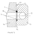
filter 2 for sealing avalve body 15 to ablock 16, for example in hydraulic units. Thebody 15 may be secured to theblock 16 by any suitable means such as threaded bolts (not shown) engaging tapped holes (not shown) in theblock 16 to connectrespective bores body 15 andblock 16. - As shown, the
block 16 has a planar mountingsurface 19 and thebody 15 has anattachment surface 20 with arecess 21 in which the combined seal 1 andfilter 2 is located. The depth of therecess 21 is such that theseal ring 3 is compressed in a controlled manner to seal the joint between thebody 15 andblock 16. Thefilter 2 extends across the passageway formed by thebores body 15 and block 16 so that solid particles contained in a fluid flowing through the passageway of a size that exceeds the mesh rating are removed. - As will be appreciated, combining the seal 1 and
filter 2 in a single component reduces from two to one the number of components to be purchased and installed with potential savings in both material costs and installation costs. Furthermore, removal of the combined seal 1 andfilter 2 for cleaning, repair and replacement is facilitated offering additional potential savings in maintenance costs. - The combined seal 1 and
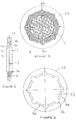
filter 2 above-described is suitable for applications in which the fluid pressure is less than 25 bar. At higher pressures, there is a risk of the seal 1 andfilter 2 deforming sufficiently for the seal 1 to extrude itself out of the gap in which it is located between the two components forming the joint to be sealed. Furthermore, as can be seen in Figures 2 and 3, theseal ring 3 is flattened under compression causing the elastomeric material to bulge at the centre where theseal ring 3 is attached to themesh 4. This may cause theseal ring 3 to tear away from themesh 4 compromising the integrity of the bond therebetween. - Referring now to Figures 4 to 6, there is shown a second embodiment of combined seal 1 and
filter 2 which is capable of withstanding higher fluid pressures and which can accommodate compression of the seal 1 without compromising the integrity of the bond therebetween. - In this embodiment, the seal 1 and
filter 2 is supported by means of an external support member comprising a flat,annular plate 22 to prevent the seal 1 extruding itself out of the gap between the two components of the joint. Theplate 22 is made of metal, for example stainless steel or brass, by pressing, stamping or punching from metal sheet of the appropriate thickness for the intended application. It will be understood however, that this is not essential and that theplate 22 may be made of other materials including plastics depending on the intended application. - The
plate 22 has acentral hole 23 with acounterbore 24 on one side and a plurality ofnotches 25 formed in the marginal edge. Thecounterbore 24 terminates in anabutment shoulder 26 and thenotches 25 extend outwards beyond thecounterbore 24 for a purpose described later herein. - The
filter 2 is made of metal by blanking out acircular mesh screen 4 from a sheet of woven mesh having the required mesh size for the intended application. Themesh screen 4 has a diameter sized to fit in thecounterbore 24 with the outer peripheral edge seated on theshoulder 26. - The seal 1 comprises a
seal ring 3 made of rubber or other elastomer suitable for the intended application that is moulded onto the peripheral edge region of themesh screen 4 within thehole 23 and bonds to thesupport plate 22 to form a unitary construction. - As in the first embodiment, a narrow area of the
mesh screen 4 spaced from the outer peripheral edge is crushed to form a crease line (not shown) blocking the interstices prior to or during moulding of theseal ring 3 to prevent the elastomer penetrating the central region of thescreen 4 forming thefilter 2. - The
notches 25 in the marginal edge of thehole 23 allow the elastomer to flow freely around the outer peripheral edge of themesh screen 4 to form theseal ring 3 on both sides of themesh screen 4. This is of particular benefit when the mesh size is small. - In this embodiment, there are eight
notches 25 uniformly spaced in the circumferential direction but it will be understood that the number and arrangement ofnotches 25 may be varied from that shown. An even number of notches, for example 2,4,6,8 etc, arranged in pairs is preferred but this is not essential and one or more notches may be employed. - The elastomer is allowed to cure in the mould and then the mould is opened to remove the
plate 22 with theseal ring 3 bonded to the marginal edge of thehole 23 and the outer peripheral edge ofmesh screen 4 embedded in theseal ring 3. Bonding of theseal ring 3 may be assisted by the application of chemical bonding agents to the surfaces of theplate 22 and/ormesh screen 4. - As shown, the
seal ring 3 has aninner portion 3a of generally trapezoidal cross-section with sealingportions 3b projecting axially outwardly from theplate 22 on each side. Theseal ring 3 has a maximum axial dimension at the innerperipheral edge 3c and the sealingportions 3b converge from the innerperipheral edge 3c and merge with anouter portion 3d which is substantially coplanar with theplate 22. - Figures 7 and 8 show the application of the reinforced seal 1 and
filter 2 of Figures 4 to 6 for sealing the joints between twopipes 6,7 (Figure 7) and between avalve body 15 and a block 16 (Figure 8) similar to the arrangements shown in Figures 2 and 3. - As shown in Figure 7, the seal 1 and
plate 22 are positioned between planar end faces of theflanges 8,9 and theplate 22 acts as a spacer to limit compression of the sealingportions 3b of the seal 1 to seal the joint between thepipes 6,7 when the clamping rings 11,12 are tightened to urge theflanges 8,9 towards each other. - The diameter of the
plate 22 is similar to the diameter of theflanges 8,9 so that the seal 1 andfilter 2 is centred between theflanges 8,9 by the inner clamping ring 11. Alternatively, theplate 22 could be of smaller diameter received in a recess in an end face of one of theflanges 8,9. - As shown in Figure 8, the
valve body 15 has arecess 21 sized to receive theplate 22 and of a depth substantially the same as the thickness of theplate 22 so that the sealingportions 3b of the seal 1 are compressed to seal the joint when thebody 15 is secured to theblock 16. - As will be appreciated, securing the
seal ring 3 to theplate 22 reinforces theseal ring 3 thereby enabling the seal 1 to withstand substantially higher pressures without extruding out of the area between the two components of the joint to be sealed. - Furthermore, as can be seen from Figures 7 and 8, the trapezoidal shape of the
inner portion 3a of the seal with maximum axial dimension at theinner edge 3c is such that, under compression, the elastomeric material of the sealingportions 3b is deflected inwardly causing theinner edge 3c of theseal ring 3 to adopt a concave profile. This movement of the elastomeric material occurs mainly at the tip regions of the sealingportions 3b with the result that there is no appreciable movement of the elastomeric material where theseal ring 3 is connected to themesh screen 4. As a consequence, it has been found that the integrity of the bond between theseal ring 3 andmesh screen 4 is substantially unaffected by compression of the seal 1. - Referring now to Figures 9 to 11, the combined seal 1 and
filter 2 of Figures 4 to 6 is shown in an assembly including an adaptor 27 for mounting the seal 1 andfilter 2 in a fluid line. The adaptor 27 comprises first andsecond parts 28,29 arranged to be threadably engaged to locate and retain the seal 1 andfilter 2 therebetween. - The
first part 28 has ahexagonal body portion 30 at one end for engagement by a spanner or like tool to rotate thebody portion 30 during assembly and anannular spigot portion 31 at the other end. - The
spigot portion 31 has anexternal screw thread 32 for threaded engagement with a complementary threaded internal bore (not shown) of the fluid line on which the adaptor 27 is installed. Alternatively, thespigot portion 31 may have an internal screw thread for engagement with an external screw thread of the fluid line. Thescrew thread 32 terminates on anexternal shoulder 33. - For some applications, the
shoulder 33 may provide a stop face to limit threaded engagement of thespigot portion 31 in the bore of the fluid line. In this case, theshoulder 33 may be provided with a seal (not shown). - The
spigot portion 31 is formed with acylindrical bore 34 corresponding to the bore of the fluid line and opening to anenlarged counterbore 35 defining asocket 36 in the body portion 29. - The
counterbore 35 is formed with aninternal screw thread 37 terminating in an internal shoulder providing anabutment face 38 for the sealingportion 3b of theseal 3 on one side of thefilter 2. - The second part 29 has a
hexagonal body portion 39 intermediate the ends for engagement by a spanner or like tool to rotate thebody portion 39 during assembly. - An
annular spigot portion 40 similar to thespigot portion 31 of thefirst part 28 is provided at one end and has anexternal screw thread 41 for threaded engagement with a complementary threaded bore (not shown) of the fluid line in which the adaptor 27 is installed. Alternatively, thespigot portion 40 may have an internal screw thread for engagement with an external screw thread of the fluid line. Thescrew thread 41 terminates in anexternal shoulder 42. In some applications, theshoulder 42 may provide a stop face to limit threaded engagement of thespigot portion 40 in the bore of the fluid line. In this case, theshoulder 42 may be provided with a seal (not shown). - A further
annular spigot portion 43 is provided at the other end defining amale plug 44 with an external screw thread 45 complementary to theinternal screw thread 37 of thecounterbore 35 defining thefemale socket 36 in thefirst part 28. - The second part 29 has a cylindrical through
bore 46 matching thebore 34 in thefirst part 28 and corresponding to the bore of the fluid line. Thebores - The
spigot portion 43 is formed with anannular counterbore 47 in the end face sized to receive thesupport member 22 to locate the seal 1 andfilter 2 transverse to the passageway. Thecounterbore 47 provides anabutment face 48 for the sealingportion 3b of theseal 3 on the other side of thefilter 2. - The diameter of the
counterbore 47 is slightly larger than the diameter of thesupport member 22 and the depth of thecounterbore 47 is slightly smaller than the thickness of thesupport member 22. In this way, thesupport member 22 is a close fit in thecounterbore 47 and projects from thecounterbore 47. - In use of the adaptor 27 to install the combined seal 1 and
filter 2 in a fluid line, thesupport member 22 is located in thecounterbore 47 at the end of thespigot portion 43 of the second part 29. The sealingportion 3b of theseal ring 3 on one side of themesh 4 contacts theabutment face 48 and thesupport member 22 projects from thecounterbore 47. - The
external thread 44 of thespigot portion 43 is then screwed into engagement with theinternal thread 37 of thecounterbore 35 in thefirst part 28. On initial tightening, theparts 28,29 are brought together axially so that the sealingportion 3b of theseal ring 3 on the other side of themesh 4 contacts theopposed abutment face 38 of thefirst part 28. - On further tightening, the
seal portions 3b are compressed due to the axial forces applied and thesupport member 22 is urged into thecounterbore 47 until theseal ring 3 is substantially flush with thesupport member 22. - In this condition, the
support member 22 projects slightly from thecounterbore 47 and is firmly clamped between the abutment faces 38,48 with the sealingportions 3b compressed against the abutment faces 38,48 to seal completely thefilter 2 in the adaptor 27. In this way, thefilter 2 is positioned transverse to the fluid passageway and is sealed on both sides to prevent leakage of fluid. - As will now be understood, the adaptor 27 ensures accurate location and facilitates installation of the
filter 2 in a fluid line transverse to the direction of fluid flow in a simple and effective manner that also facilitates access to thefilter 2 for cleaning, repair or replacement during routine maintenance and/or in an emergency. - In the above-described embodiment, the
support member 22 limits compression of the seal 1 in the assembled adaptor 27. It will be understood, however, that thesupport member 22 may be omitted and thefilter 2 with integral seal 1 mounted in thecounterbore 47 so that compression of the seal 1 is controlled by engagement of theparts 28,29. - Referring now to Figures 12 to 14, there is shown a third embodiment of combined seal 1 and
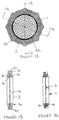
filter 2 similar to that shown in Figures 4 to 6 but with theouter support plate 22 omitted. The crease line for preventing penetration of the seal material to the centre region of themesh 4 is indicated byreference numeral 49. - This embodiment may be produced by moulding the seal 1 onto the
filter 2 in a mould containing thesupport plate 22 without any bonding agent being applied so that the seal 1 does not bond thesupport plate 22. As a result, the combined seal 1 andfilter 2 can be separated from thesupport plate 22 on completion of moulding. In this way, the same mould can be used to make the combined seal 1 andfilter 2 with or without the additional reinforcement provided by thesupport plate 22 depending on the intended application of the seal 1 andfilter 2. - As will be appreciated, when the seal 1 and
filter 2 are separated from thesupport plate 22, thenotches 25 provided in thesupport plate 22 produce a series of outwardly projectinglobes 50 uniformly spaced apart around the outer peripheral edge of the seal 1. Theselobes 50 assist in locating and centering the seal 1 andfilter 2 when installed in a fluid line, particularly when the seal 1 andfilter 2 are received in a counterbore having a diameter corresponding to the maximum diameter of the seal 1. Thus, variations in the dimensions of the counterbore such as may occur through manufacturing tolerances are accommodated by deformation of thelobes 50 in a manner that would not be possible if thelobes 50 were omitted. As will be appreciated, the number and position oflobes 50 may be varied from that shown although a symmetrical arrangement is generally preferred for centering the seal 1 andfilter 2. - Referring now to Figures 15 and 16, a twin seal 1 and
filter 2 arrangement is shown mounted in acommon support plate 22 for sealing two joints. As shown, one seal 1 andfilter 2 is of L-shape and the other is of rectangular shape with theplate 22 havingholes 23 of matching shape. The materials and method of forming each seal 1 andfilter 2 are similar to the second embodiment with eachseal ring 3 having aninner portion 3a of trapezoidal shape. Other shapes and configurations of seal 1 andfilter 2 and/orplate 22 may be employed to suit the joint to be sealed. Furthermore, it will readily be appreciated that by providing more than one seal 1 andfilter 2 in acommon plate 22, several joints can be sealed using a single component thereby facilitating installation, for example when connecting a number of fittings to a hydraulic block. - It will be understood that the invention is not limited to the embodiments above-described. For example, the seal 1 may be made of any suitable elastomer or resilient plastics capable of sealing when compressed. The
seal ring 3 may be of circular or non-circular cross-section. A section which reduces the stress on the bond between the seal 1 andfilter 2 when the seal 1 is compressed is generally preferred such as the trapezoidal section shown in some of the exemplary embodiments. Thefilter 2 may be made of metal or plastics and the centre region may be flat or dome-shaped to increase the area of the filter. - The combined seal 1 and
filter 2 may be of annular shape or any other suitable shape, for example oval, elliptical, rectangular, L-shape, T-shape or the like depending on the cross-section of the passageway to be sealed. - Where provided, the
support plate 22 may be made of metal or plastics and may be flat or any other suitable shape for locating between the opposed faces of the components forming the joint to be sealed. Thesupport plate 22 may be of annular shape or any other suitable shape. Thesupport plate 22 may be provided with means to indicate the orientation for installation of the seal 1 andfilter 2 in a fluid line. The indicator means may be a mark, letter, numeral or other suitable indicia for establishing the correct way to fit thesupport plate 2. More than one seal 1 andfilter 2 may be provided in thesame support plate 22 depending on the number and arrangement of the joints to be sealed. Where thesupport plate 22 is omitted, the seal 1 may be formed at the outer edge with one or more outwardly projectinglobes 50 or similar formation(s). Other modifications will be apparent to these of ordinary skill in the art. - Finally, it will be understood that the invention includes any feature or combination of features described herein and the scope of the invention is to be construed accordingly.
Claims (13)
- An integral seal and filter assembly for a fluid line comprising a seal bonded to a peripheral edge region of a filter, the seal having resilient sealing portions on each side of the filter which, in use, are compressible between opposed faces of relatively axially movable components to effect a seal therebetween with the filter extending across a fluid passageway through the components.
- The assembly according to claim 1 characterised in that, the filter has a barrier separating the peripheral edge region from a centre region for confining the seal to the peripheral edge region.
- An assembly according to claim 2 characterised in that the filter comprises a mesh screen and the barrier comprises a crease formed by crushing a narrow region of the mesh inwardly of the peripheral edge region.
- An assembly according to claim 2 characterised in that the filter comprises a mesh screen having an array of perforations formed by photochemical machining a preform and the barrier comprises a region free from perforations formed by masking the preform during the machining operation.
- An assembly according to any one of the preceding claims characterised in that the seal is of polygonal cross-section, preferably having a generally trapezoidal section with sealing surfaces on each side of the filter that converge towards each other from an inner edge of the seal.
- An assembly according to claim 5 characterised in that the inner edge is substantially flat in an uncompressed condition of the seal and is substantially concave in a compressed condition.
- An assembly according to any one of the preceding claims characterised in that an outer support member is provided with a hole locating the seal and filter, and the seal projects axially outwardly from the plate on both sides and is bonded to a marginal edge of the hole.
- A method of forming an integral seal and filter assembly comprising providing a filter and bonding a seal to a marginal edge portion of the filter so that the seal provides sealing portions on each side of the filter that are compressible to effect a seal between relatively axially movable components.
- The method according to claim 8 characterised in that, an outer support member is provided having a hole for reception of the seal and filter assembly, and the seal is bonded to a marginal edge of the hole and has a sealing portion of trapezoidal section inwardly of the hole with sealing surfaces projecting from the support member on each side and convergent from an inner edge of the seal towards the support member.
- A method of forming a fluid tight joint between first and second components in a fluid line comprising providing an integral seal and filter element, positioning the element with the seal between opposed faces of the first and second components and the filter extending across the fluid line, and relatively moving the first and second components in an axial direction to compress the seal between the opposed faces on each side of the filter.
- An assembly for mounting in a fluid line, the assembly including an adaptor having first and second parts releasably connectable to define a passageway for flow of fluid therethrough, a filter, and a seal integral with a marginal edge of the filter, the seal being arranged to contact opposed abutment faces of the first and second parts on each side of the filter and being compressed therebetween when the first and second parts are connected to seal the filter in the adaptor with the filter extending across the passageway.
- The assembly according to claim 11 characterised in that, the first and second parts have co-operating screw threads arranged for relative axial movement of the first and second parts to urge the abutment faces axially towards each other to compress the seal therebetween during assembly of the adaptor.
- The assembly according to claim 11 or claim 12 characterised in that, the seal is bonded to a marginal edge of a hole in a support plate, the hole being formed with a counterbore providing a seating for the marginal edge of the filter, and the seal having a sealing portion inwardly of the marginal edge of the hole and projecting axially from the hole on each side of the support plate, the sealing portion being of generally trapezoidal section with sealing surfaces on side of the support plate that are convergent from an inner edge region of the seal towards the support member.
Applications Claiming Priority (4)
| Application Number | Priority Date | Filing Date | Title |
|---|---|---|---|
| GB9923437 | 1999-10-05 | ||
| GBGB9923437.9A GB9923437D0 (en) | 1999-10-05 | 1999-10-05 | Improvements in or relating to fluids seals |
| GB0017455 | 2000-07-18 | ||
| GB0017455A GB0017455D0 (en) | 2000-07-18 | 2000-07-18 | IMprovements in or relating to fluid filters |
Publications (2)
| Publication Number | Publication Date |
|---|---|
| EP1091156A2 true EP1091156A2 (en) | 2001-04-11 |
| EP1091156A3 EP1091156A3 (en) | 2002-05-29 |
Family
ID=26244671
Family Applications (1)
| Application Number | Title | Priority Date | Filing Date |
|---|---|---|---|
| EP00308711A Withdrawn EP1091156A3 (en) | 1999-10-05 | 2000-10-04 | Improvements in or relating to fluid seals |
Country Status (3)
| Country | Link |
|---|---|
| US (1) | US6547255B1 (en) |
| EP (1) | EP1091156A3 (en) |
| GB (1) | GB2356581B (en) |
Cited By (9)
| Publication number | Priority date | Publication date | Assignee | Title |
|---|---|---|---|---|
| EP1548291A2 (en) * | 2003-12-22 | 2005-06-29 | Volvo Construction Equipment Holding Sweden AB | Coin-filter mounting structure |
| FR2872251A1 (en) * | 2004-06-23 | 2005-12-30 | F P Automatismes Sarl | Hydraulic fluid line for connecting pipe in hydraulic circuit of hydraulic machine e.g. positioning carriage, has filtering pellet retained by locking sleeve in appropriate position for being traversed by fluid circulating in drilling |
| JP2007064486A (en) * | 2005-08-31 | 2007-03-15 | Skf Ab | Sealing structure |
| CN101994885A (en) * | 2009-08-11 | 2011-03-30 | 维克托里克公司 | Seal with rigid stop ring |
| CN105156789A (en) * | 2015-09-24 | 2015-12-16 | 江苏广通管业制造有限公司 | Flange gasket |
| CN106224670A (en) * | 2016-10-08 | 2016-12-14 | 湖北三江航天红林探控有限公司 | A kind of shock resistance anti-loosing type high-temperature sealing device |
| DE102018219992A1 (en) * | 2018-11-22 | 2020-05-28 | Zf Friedrichshafen Ag | Device for separating dirt particles from the flow of several hydraulic transfer points between a first component and at least a second component |
| CN111841091A (en) * | 2020-06-16 | 2020-10-30 | 中交第三公路工程局有限公司 | Sludge discharge facility |
| CN113074284A (en) * | 2021-03-02 | 2021-07-06 | 侬昌跃 | Clean gas of coal system is with transmission butt joint leak protection device |
Families Citing this family (47)
| Publication number | Priority date | Publication date | Assignee | Title |
|---|---|---|---|---|
| BR0202511A (en) * | 2002-07-03 | 2004-05-11 | Manegro Administracao E Partic | Pipe and equipment flange gasket, gasket manufacturing process, and gasket for gasket |
| WO2005001315A2 (en) * | 2003-06-25 | 2005-01-06 | Garlock Sealing Technologies, Llc | Rebuildable composite seal |
| US20070000834A1 (en) * | 2005-07-01 | 2007-01-04 | Poston Daniel R | Oil canning of mesh screen for filter |
| DE602007004546D1 (en) | 2006-09-28 | 2010-03-18 | Tyco Healthcare | Portable wound therapy system |
| US20080128993A1 (en) * | 2006-11-30 | 2008-06-05 | Freudenberg-Nok General Partnership | Bonded Filter Gasket With Raised Sealing Beads |
| US20080217360A1 (en) * | 2007-03-05 | 2008-09-11 | Illinois Tool Works Inc. | Hot melt adhesive dispensing valve or module assembly having a module filter disposed therewithin |
| GB0712763D0 (en) | 2007-07-02 | 2007-08-08 | Smith & Nephew | Apparatus |
| GB0803564D0 (en) | 2008-02-27 | 2008-04-02 | Smith & Nephew | Fluid collection |
| US8298200B2 (en) | 2009-06-01 | 2012-10-30 | Tyco Healthcare Group Lp | System for providing continual drainage in negative pressure wound therapy |
| US8021347B2 (en) | 2008-07-21 | 2011-09-20 | Tyco Healthcare Group Lp | Thin film wound dressing |
| US20090236805A1 (en) * | 2008-03-21 | 2009-09-24 | Rubber Fab Gasket And Molding, Inc.. | Gauge guard for sanitary piping system |
| US10912869B2 (en) | 2008-05-21 | 2021-02-09 | Smith & Nephew, Inc. | Wound therapy system with related methods therefor |
| US8414519B2 (en) | 2008-05-21 | 2013-04-09 | Covidien Lp | Wound therapy system with portable container apparatus |
| US8177763B2 (en) * | 2008-09-05 | 2012-05-15 | Tyco Healthcare Group Lp | Canister membrane for wound therapy system |
| AU2009268997B2 (en) * | 2008-07-08 | 2015-04-02 | Smith & Nephew Inc. | Portable negative pressure wound therapy device |
| WO2010017437A1 (en) | 2008-08-08 | 2010-02-11 | Tyco Healthcare Group Lp | Wound dressing of continuous fibers |
| US8827983B2 (en) | 2008-08-21 | 2014-09-09 | Smith & Nephew, Inc. | Sensor with electrical contact protection for use in fluid collection canister and negative pressure wound therapy systems including same |
| US20100191198A1 (en) * | 2009-01-26 | 2010-07-29 | Tyco Healthcare Group Lp | Wound Filler Material with Improved Nonadherency Properties |
| US20100204752A1 (en) * | 2009-02-10 | 2010-08-12 | Tyco Healthcare Group Lp | Negative Pressure and Electrostimulation Therapy Apparatus |
| KR101019714B1 (en) * | 2009-04-01 | 2011-03-07 | 쓰리디이미징앤시뮬레이션즈(주) | Apparatus for acquiring digital X-ray image |
| US20110196321A1 (en) | 2009-06-10 | 2011-08-11 | Tyco Healthcare Group Lp | Fluid Collection Canister Including Canister Top with Filter Membrane and Negative Pressure Wound Therapy Systems Including Same |
| US20100318043A1 (en) * | 2009-06-10 | 2010-12-16 | Tyco Healthcare Group Lp | Negative Pressure Wound Therapy Systems Capable of Vacuum Measurement Independent of Orientation |
| US20100318071A1 (en) * | 2009-06-10 | 2010-12-16 | Tyco Healthcare Group Lp | Fluid Collection Canister Including Canister Top with Filter Membrane and Negative Pressure Wound Therapy Systems Including Same |
| US20100324516A1 (en) * | 2009-06-18 | 2010-12-23 | Tyco Healthcare Group Lp | Apparatus for Vacuum Bridging and/or Exudate Collection |
| US20110106027A1 (en) * | 2009-11-05 | 2011-05-05 | Tyco Healthcare Group Lp | Chemically Coated Screen for Use with Hydrophobic Filters |
| FR2964328B1 (en) * | 2010-09-03 | 2012-10-05 | Alfa Laval Moatti | METHOD FOR MANUFACTURING A FILTER ELEMENT |
| US9302034B2 (en) | 2011-04-04 | 2016-04-05 | Smith & Nephew, Inc. | Negative pressure wound therapy dressing |
| JP5875306B2 (en) * | 2011-09-22 | 2016-03-02 | 東京エレクトロン株式会社 | Pipe fitting |
| US8961225B2 (en) | 2012-03-16 | 2015-02-24 | Bren-Tronics, Inc. | Flexible water-tight seal for a movable component |
| JP5988822B2 (en) * | 2012-10-19 | 2016-09-07 | 株式会社フジキン | Pipe fitting |
| US9228683B2 (en) * | 2013-12-22 | 2016-01-05 | Saint-Gobain Performance Plastics Corporation | Flanged tube apparatus |
| USD886253S1 (en) | 2018-03-15 | 2020-06-02 | Garlock Pipeline Technologies, Llc | Gasket |
| US10920914B2 (en) * | 2014-01-29 | 2021-02-16 | Garlock Pipeline Technologies, Inc. | Sealing system having interlocking inner diameter seal element to resist pressure changes |
| FR3022799B1 (en) * | 2014-06-25 | 2017-12-29 | Airbus Operations Sas | AIR FILTER FOR COLLECTING DEBRIS IN A VENTILATION PIPING OF AN AIRCRAFT |
| US10054249B2 (en) * | 2014-07-24 | 2018-08-21 | Ags Company Automotive Solutions Llc | Universal tube fitting adaptable for different sized tubes |
| US10744239B2 (en) | 2014-07-31 | 2020-08-18 | Smith & Nephew, Inc. | Leak detection in negative pressure wound therapy system |
| EP3198174B1 (en) * | 2014-09-23 | 2020-04-22 | Fr. Jacob Söhne GmbH & Co. KG | Folded sealing ring |
| US10738921B2 (en) * | 2016-08-25 | 2020-08-11 | Marc Rowley | Non-metallic high pressure high temperature high chemical compatibility flange isolation gasket |
| US20180094756A1 (en) | 2016-10-05 | 2018-04-05 | Garlock Pipeline Technologies, Inc. | Gasket with electrical isolating coatings |
| US11898637B2 (en) | 2016-10-05 | 2024-02-13 | Gpt Industries, Llc | Gasket with electrical isolating coatings |
| CN106838504B (en) * | 2017-02-17 | 2018-10-19 | 平罗县龙江液化气有限责任公司 | A kind of conveyance conduit of liquefied natural gas |
| US10655679B2 (en) * | 2017-04-07 | 2020-05-19 | United Technologies Corporation | Oil control for seal plates |
| EP3612242A1 (en) | 2017-04-19 | 2020-02-26 | Smith & Nephew, Inc | Negative pressure wound therapy canisters |
| JP6356893B1 (en) * | 2017-10-02 | 2018-07-11 | 井上スダレ株式会社 | Pipe joint structure |
| US10624794B2 (en) | 2018-02-12 | 2020-04-21 | Healyx Labs, Inc. | Negative pressure wound therapy systems, devices, and methods |
| US20220235891A1 (en) * | 2021-01-25 | 2022-07-28 | Hutchinson Fluid Management Systems, Inc. | Dual plane seal air conditioner connector |
| US11655921B2 (en) * | 2021-03-11 | 2023-05-23 | Pratt & Whitney Canada Corp. | Multi-seal coupling for a hydrogen fuel system of a gas turbine engine |
Family Cites Families (22)
| Publication number | Priority date | Publication date | Assignee | Title |
|---|---|---|---|---|
| US282093A (en) * | 1883-07-31 | Milk-skimmer | ||
| US1236100A (en) * | 1917-03-21 | 1917-08-07 | Franklin Gas Turbine Company | Gasket-screen. |
| US1329398A (en) * | 1919-01-27 | 1920-02-03 | David M Hutchinson | Washer for hose-couplings |
| US2015087A (en) * | 1932-11-03 | 1935-09-24 | Rafton Engineering Corp | Wire cloth supporting and attaching means |
| US2153664A (en) * | 1937-03-08 | 1939-04-11 | Dayton Rubber Mfg Co | Strainer |
| US2288532A (en) * | 1939-09-12 | 1942-06-30 | Budd L Knapp | Filter device |
| FR1275059A (en) * | 1960-09-24 | 1961-11-03 | Device for immobilizing an attached part in a hollow body | |
| DE1222892B (en) * | 1961-08-10 | 1966-08-18 | Basf Ag | Filter nozzle made of plastic that can be processed by injection molding |
| US3206216A (en) * | 1962-05-23 | 1965-09-14 | Westinghouse Electric Corp | Fluid pressure seal assemblage |
| US3421631A (en) * | 1965-10-22 | 1969-01-14 | Charles K Hirsch | Strainer gasket for sanitary piping systems |
| US3622008A (en) * | 1969-12-22 | 1971-11-23 | Flexitallic Gasket Co Inc | Compression gasket and screen assembly |
| GB1303302A (en) * | 1970-02-13 | 1973-01-17 | ||
| US3707832A (en) * | 1970-08-12 | 1973-01-02 | Scient Glass Blowing Co | Filter and filter support apparatus |
| BE795108A (en) * | 1972-03-23 | 1973-05-29 | Flexitallic Gasket Co Inc | METHOD AND APPARATUS SUCH AS AN AUTOMATIC DRAINER, FOR EVACUATING CONDENSATE FROM HIGH PRESSURE STEAM PIPES |
| AT365090B (en) * | 1980-04-16 | 1981-12-10 | Inkomag | FILTRATION DEVICE |
| US4664800A (en) * | 1985-03-18 | 1987-05-12 | Burron Medical Inc. | Micron chamber I.V. with support ring |
| US5456475A (en) * | 1988-04-28 | 1995-10-10 | Skf Usa Inc. | Protected seal assembly and protective filter unit therefor |
| CA1312831C (en) | 1988-09-22 | 1993-01-19 | Pierre P. Meunier | Compression seal canister |
| DE4325235C2 (en) * | 1993-07-28 | 1995-08-31 | Junker Filter Gmbh | Filter element for a chamber, membrane filter or the like and method for its production |
| FR2711764A1 (en) * | 1993-10-26 | 1995-05-05 | Cpmh Mecanique | Screens for protecting pipes and accessories when making a pipework installation live |
| JP4031843B2 (en) * | 1995-08-22 | 2008-01-09 | ローベルト ボツシユ ゲゼルシヤフト ミツト ベシユレンクテル ハフツング | Seal element for hydraulic unit and method of manufacturing seal element |
| US5758882A (en) * | 1997-01-24 | 1998-06-02 | Pipeline Seal & Insulator, Inc. | Screened gasket for high pressure fluid transmission applications |
-
2000
- 2000-10-04 EP EP00308711A patent/EP1091156A3/en not_active Withdrawn
- 2000-10-05 GB GB0024359A patent/GB2356581B/en not_active Expired - Fee Related
- 2000-10-05 US US09/680,002 patent/US6547255B1/en not_active Expired - Fee Related
Non-Patent Citations (1)
| Title |
|---|
| None |
Cited By (16)
| Publication number | Priority date | Publication date | Assignee | Title |
|---|---|---|---|---|
| EP1548291A2 (en) * | 2003-12-22 | 2005-06-29 | Volvo Construction Equipment Holding Sweden AB | Coin-filter mounting structure |
| EP1548291A3 (en) * | 2003-12-22 | 2005-10-05 | Volvo Construction Equipment Holding Sweden AB | Coin-filter mounting structure |
| US7141165B2 (en) | 2003-12-22 | 2006-11-28 | Volvo Construction Equipment Holding Sweden Ab | Coin-filter mounting structure |
| FR2872251A1 (en) * | 2004-06-23 | 2005-12-30 | F P Automatismes Sarl | Hydraulic fluid line for connecting pipe in hydraulic circuit of hydraulic machine e.g. positioning carriage, has filtering pellet retained by locking sleeve in appropriate position for being traversed by fluid circulating in drilling |
| JP2007064486A (en) * | 2005-08-31 | 2007-03-15 | Skf Ab | Sealing structure |
| EP1760370A3 (en) * | 2005-08-31 | 2007-08-22 | Ab Skf | Sealing |
| DE102005041553B4 (en) * | 2005-08-31 | 2016-03-24 | Ab Skf | seal |
| US8052151B2 (en) | 2005-08-31 | 2011-11-08 | Ab Skf | Sealing arrangement |
| EP2284423B1 (en) * | 2009-08-11 | 2012-08-29 | Victaulic Company | Seal with rigid stop ring |
| CN101994885A (en) * | 2009-08-11 | 2011-03-30 | 维克托里克公司 | Seal with rigid stop ring |
| CN105156789A (en) * | 2015-09-24 | 2015-12-16 | 江苏广通管业制造有限公司 | Flange gasket |
| CN105156789B (en) * | 2015-09-24 | 2017-06-30 | 佛山市源仕液压密封科技有限公司 | A kind of flange gasket |
| CN106224670A (en) * | 2016-10-08 | 2016-12-14 | 湖北三江航天红林探控有限公司 | A kind of shock resistance anti-loosing type high-temperature sealing device |
| DE102018219992A1 (en) * | 2018-11-22 | 2020-05-28 | Zf Friedrichshafen Ag | Device for separating dirt particles from the flow of several hydraulic transfer points between a first component and at least a second component |
| CN111841091A (en) * | 2020-06-16 | 2020-10-30 | 中交第三公路工程局有限公司 | Sludge discharge facility |
| CN113074284A (en) * | 2021-03-02 | 2021-07-06 | 侬昌跃 | Clean gas of coal system is with transmission butt joint leak protection device |
Also Published As
| Publication number | Publication date |
|---|---|
| GB0024359D0 (en) | 2000-11-22 |
| GB2356581A (en) | 2001-05-30 |
| EP1091156A3 (en) | 2002-05-29 |
| GB2356581B (en) | 2003-08-20 |
| US6547255B1 (en) | 2003-04-15 |
Similar Documents
| Publication | Publication Date | Title |
|---|---|---|
| US6547255B1 (en) | Fluid seals | |
| US5533764A (en) | Transverse hydraulic coupling with lipped port | |
| US6695357B2 (en) | Threaded pipe connection having a retainer gasket with pressure relief vents | |
| US5011162A (en) | Bi-lobed sealing element and retainer | |
| CA2730006C (en) | Extrusion resistant gasket face seal | |
| US6325090B1 (en) | Backflow preventer assembly | |
| US3844531A (en) | Slide valve | |
| US4934742A (en) | Hydraulic coupling | |
| EP2905515A1 (en) | Gasket | |
| GB2142416A (en) | Valve seat for fluid flow control valve | |
| EP0389250A1 (en) | Cantilever lip conduit coupling member and assembly | |
| EP1180631A2 (en) | Hose end fitting | |
| US6669205B2 (en) | Retainer gasket with pressure relief vents | |
| CA2513827C (en) | Straight thread adjustable port end | |
| EP1982101A2 (en) | Sealed flange joint for high pressure and high purity gas channels | |
| US5000488A (en) | Adapter fittings and connectors | |
| CA2916041A1 (en) | Seal ring structure for high-pressure pipe joint | |
| CA2179534A1 (en) | Hot-tapping sleeve | |
| CA2520964C (en) | O-ring forming sealing washer | |
| US7527299B1 (en) | Container discharge and fill port fitting | |
| US3272534A (en) | Flexible band coupling with tapped insert | |
| JPH04214972A (en) | Seal for connecting tube to housing member and forming method thereof | |
| GB2083556A (en) | Pressure vessel assemblies | |
| CN1607326A (en) | Oil filter gasket with flap | |
| US5115550A (en) | Adjustable O-ring port fitting for a hydraulic coupling |
Legal Events
| Date | Code | Title | Description |
|---|---|---|---|
| PUAI | Public reference made under article 153(3) epc to a published international application that has entered the european phase |
Free format text: ORIGINAL CODE: 0009012 |
|
| AK | Designated contracting states |
Kind code of ref document: A2 Designated state(s): AT BE CH CY DE DK ES FI FR GB GR IE IT LI LU MC NL PT SE |
|
| AX | Request for extension of the european patent |
Free format text: AL;LT;LV;MK;RO;SI |
|
| PUAL | Search report despatched |
Free format text: ORIGINAL CODE: 0009013 |
|
| AK | Designated contracting states |
Kind code of ref document: A3 Designated state(s): AT BE CH CY DE DK ES FI FR GB GR IE IT LI LU MC NL PT SE |
|
| AX | Request for extension of the european patent |
Free format text: AL;LT;LV;MK;RO;SI |
|
| 17P | Request for examination filed |
Effective date: 20021125 |
|
| AKX | Designation fees paid |
Designated state(s): AT BE CH CY DE DK ES FI FR GB GR IE IT LI LU MC NL PT SE |
|
| 17Q | First examination report despatched |
Effective date: 20040929 |
|
| GRAP | Despatch of communication of intention to grant a patent |
Free format text: ORIGINAL CODE: EPIDOSNIGR1 |
|
| RTI1 | Title (correction) |
Free format text: INTEGRAL SEAL AND FILTER ASSEMBLY |
|
| STAA | Information on the status of an ep patent application or granted ep patent |
Free format text: STATUS: THE APPLICATION IS DEEMED TO BE WITHDRAWN |
|
| 18D | Application deemed to be withdrawn |
Effective date: 20050923 |