EP1091032A2 - A let-off control device for a weaving machine - Google Patents

A let-off control device for a weaving machine Download PDF

Info

Publication number
EP1091032A2
EP1091032A2 EP00120680A EP00120680A EP1091032A2 EP 1091032 A2 EP1091032 A2 EP 1091032A2 EP 00120680 A EP00120680 A EP 00120680A EP 00120680 A EP00120680 A EP 00120680A EP 1091032 A2 EP1091032 A2 EP 1091032A2
Authority
EP
European Patent Office
Prior art keywords
tension
controller
calculator
weaving machine
control device
Prior art date
Legal status (The legal status is an assumption and is not a legal conclusion. Google has not performed a legal analysis and makes no representation as to the accuracy of the status listed.)
Withdrawn
Application number
EP00120680A
Other languages
German (de)
French (fr)
Other versions
EP1091032A3 (en
Inventor
Tsutomu Tsudakoma Kogyo Kabushiki Kaisha Sainen
Current Assignee (The listed assignees may be inaccurate. Google has not performed a legal analysis and makes no representation or warranty as to the accuracy of the list.)
Tsudakoma Corp
Original Assignee
Tsudakoma Industrial Co Ltd
Priority date (The priority date is an assumption and is not a legal conclusion. Google has not performed a legal analysis and makes no representation as to the accuracy of the date listed.)
Filing date
Publication date
Application filed by Tsudakoma Industrial Co Ltd filed Critical Tsudakoma Industrial Co Ltd
Publication of EP1091032A2 publication Critical patent/EP1091032A2/en
Publication of EP1091032A3 publication Critical patent/EP1091032A3/en
Withdrawn legal-status Critical Current

Links

Images

Classifications

    • DTEXTILES; PAPER
    • D03WEAVING
    • D03DWOVEN FABRICS; METHODS OF WEAVING; LOOMS
    • D03D49/00Details or constructional features not specially adapted for looms of a particular type
    • D03D49/04Control of the tension in warp or cloth
    • D03D49/06Warp let-off mechanisms

Definitions

  • This invention relates to a let-off control device for a weaving machine capable of achieving desirable controllability in a stable fashion regardless of variations in rotational speed of the weaving machine.
  • a let-off control device of a weaving machine controls a warp beam via a let-off motor in such a way that a specific warp tension is maintained.
  • a conventionally known problem of the let-off control device is that if a simple feedback control system is configured and a large integration time constant is inserted in a warp tension detecting system, overall response significantly deteriorates, making it difficult to achieve a specific degree of controllability. This is because the warp tension considerably fluctuates during each rotation of a main shaft of the weaving machine due to a various operations of the weaving machine such as a warp shedding motion during which a peak warp tension could rise up to as much as twice of the average warp tension.
  • Japanese Unexamined Patent Publication No. 59-157354 proposes a let-off control device of a weaving machine to overcome the aforementioned problem.
  • This let-off control device calculates a basic speed of a let-off motor based on the rotational speed of the weaving machine and warp winding diameter on its warp beam, detects warp tension at a specific angle of rotation (hereinafter referred to as the crank angle) of a main shaft during its each successive turn, calculates the amount of speed correction for the let-off motor based on an moving average of the warp tension, and controls the speed of the let-off motor based on the basic speed corrected by the calculated amount of speed correction.
  • the crank angle a specific angle of rotation
  • a controller for calculating the amount of speed correction has control elements for performing proportional, integral and differential (control) actions and calculates the amount of speed correction each time the moving average of the warp tension is calculated. Therefore, it is not necessary to insert a large integration time constant in a warp tension detecting system and it is possible to achieve desirable controllability by using correction control by a feedback control system based on the moving average of the warp tension in addition to a feed-forward control system based on the basic speed.
  • a time delay (a lag element; a time delay), i.e., from the time detecting a warp tension to the time the corrected speed is output, can be maintained at substantially a constant value.
  • a time delay i.e., from the time detecting a warp tension to the time the corrected speed is output
  • the aforementioned let-off control device employing said PID controller readjustment of a control gain, in particular a proportional gain, for the PID controller is necessitated.
  • the proportional gain (gain value) having suitably adjusted for a low speed weaving operation
  • the adjusted time delay factor would be too long for the high speed operation.
  • the proportional gain set for the low speed weaving operation will be too large for the proportional gain needed for the effective control in the high speed weaving operation.
  • the control gain i.e., not only a proportional gain but also an integral gain and a differential gain, is changed in accordance with the speed of the weaving operation, the effective control of the weaving operation cannot be performed.
  • the controller calculating the amount of speed correction calculates the amount of speed correction each time the moving average of the warp tension is calculated, that is, the amount of speed correction is calculated every rotation of the main shaft of the weaving machine.
  • the prior art technology has a problem that it is difficult to maintain desirable controllability. Because when the rotational speed of the weaving machine changes due to the particular weaving operation, leading to the change in sampling time (frequency), what was previously optimum control gain adjusted prior to the change in rotational speed is no longer the optimum gain for the weaving operation after the change in rotational speed. It is, thus, highly likely that those previously adjusted gain values (for the control gain) are in excess or in lack with respect to the optimum values for the new weaving operation at new rotational speed. Accordingly, with the aforementioned prior art technology, unless the control gain is readjusted at the time of change in rotational speed of the weaving machine, it becomes difficult to maintain the desirable controllability.
  • a second object of the invention is to provide a let-off control device for a weaving machine which can automatically set optimum control parameters for a controller for calculating the amount of speed correction with an additional provision of an automatic tuning circuit, and thereby achieve desirable controllability with ease.
  • a let-off control device of the invention for a weaving machine comprises a basic speed calculator for calculating a basic speed of a let-off motor, an average tension calculator for calculating a moving average of warp tension detected at a specific crank angle in one or more picks, a controller for calculating a speed correction value for the let-off motor based on deviation of average tension fed from the average tension calculator with respect to a target tension, and a control amplifier for controlling the speed of the let-off motor based on the basic speed fed from the basic speed calculator and the speed correction value fed from the controller, wherein the controller operates in synchronism with an operating cycle which is independent from an operating cycle of the average tension calculator.
  • the average tension calculator obtains the average tension by calculating the moving average of the warp tension at the specific crank angle during multiple picks. Specifically, the average tension calculator detects the warp tension at the specific crank angle in each successive rotation of a main shaft of the weaving machine and determines the average tension by calculating the moving average of the warp tension thus detected during the most recent rotations of the main shaft. Accordingly, the operating cycle of the average tension calculator is completely synchronized with the rotations of the main shaft.
  • the controller since the controller operates in synchronism with the operating cycle which is independent from the operating cycle of the average tension calculator, there is no likelihood that sampling time varies and thereby substantial control parameter loses its optimum state even when the rotational speed of the weaving machine changes.
  • the controller operates according to a clock signal independent of the rotational speed of the weaving machine and may include control elements for performing proportional, integral and differential (control) actions, or those for performing proportional and integral (control) actions only.
  • the controller operates in synchronism with the operating cycle which is shorter than the operating cycle of the average tension calculator.
  • the let-off control device may further comprise a correction calculator for adjusting the speed correction value fed from the controller based on the winding diameter of warp on a let-off beam.
  • the speed correction value fed from the controller is adjusted by the correction calculator based on the winding diameter of warp on the let-off beam, it becomes possible to achieve good controllability. This is because, although a transfer function of a mechanical system from the let-off motor to the warp tension varies when the winding diameter of the warp on the let-off beam decreases due to the consumption of the warp for instance, the correction calculator can properly compensate for such variations.
  • the let-off control device may further comprise a switching circuit which disables the controller when a tuning command is issues, and an automatic tuning circuit which updates a control parameter of the controller by producing the tuning command.
  • the controller can be disabled by the switching circuit and, then, the automatic tuning circuit can automatically set the control parameter of the controller by producing the tuning command.
  • the automatic tuning circuit can transmit an appropriate driving signal to the let-off motor, find the transfer function of the mechanical system from the let-off motor to the warp tension by monitoring variations with time of the warp tension caused by the driving signal, determine the optimum control parameter for the transfer function, and automatically set it in the controller.
  • the switcher switching circuit
  • the tuning command should be generated by manual operation or by appropriate automatic means.
  • the automatic tuning circuit may include a proportional controller which generates a driving signal to be delivered to the let-off motor based on the deviation of the warp tension with respect to the target tension, and a tension data detector which detects variations in the warp tension caused by the driving signal fed from the proportional controller.
  • the automatic tuning circuit may include a signal generator which generates a driving signal to be delivered to the let-off motor, and a regression analyzer which performs regression analysis of variations in the warp tension caused by the driving signal fed from the signal generator.
  • the automatic tuning circuit finds and analyzes a step response of a feedback control system formed of the proportional controller and a controlled system by means of the tension data detector, and thus determines the transfer function of the controlled system, and find the optimum control parameter.
  • the automatic tuning circuit can perform regression analysis of the variations in the warp tension by means of the regression analyzer after the signal generator has transmitted the driving signal to the let-off motor, determine the transfer function of the controlled system using results of the analysis, and find the optimum control parameter.
  • the driving signal output from the signal generator to the let-off motor may be of a fixed level maintained for a specific time period so that appropriate variations with time of the warp tension would be obtained.
  • the let-off control device may further comprise a compensating circuit for improving response to the target tension.
  • the compensating circuit would help improve response to the target tension. It forms a control system having two degrees of freedom together with the controller and would optimize response of the controller not only to external disturbances but also to variations in the warp tension.
  • a let-off control device 10 of a weaving machine comprises as its principal elements a basic speed calculator 11, a controller 14, a control amplifier 17 and an average tension calculator 18. An output of the control device 10 is connected to a let-off motor M.
  • the let-off motor M is connected to a warp beam WB via a reduction gear unit GD.
  • Warp threads W fed from the warp beam WB are pulled out over a tension roller TR and separated into two sets of warp threads, upper warp threads W1 and lower warp threads W2, by a heddle which is not illustrated.
  • the tension roller TR is associated with a detector LD, such as a load cell, which detects warp tension Y exerted on the tension roller TR on a real-time basis.
  • the warp beam WB is associated with a winding diameter sensor DS which detects winding diameter D of (the warp W on) the warp beam WB.
  • Weft density A of an in-process fabric, gear ratio m of the reduction gear unit GD, rotational speed N of the weaving machine and the winding diameter D fed from the winding diameter sensor DS are entered to the basic speed calculator 11, where the weft density A and the gear ratio m are set on an unillustrated setter while the rotational speed N of the weaving machine is output from an unillustrated rotational speed detector.
  • An output of a target tension setter 12 is connected to the controller 14 via an summing point 13. Also, an output of the controller 14 is connected to the let-off motor M via a correction calculator 15, an summing point 16 and the control amplifier 17. Outputs of the average tension calculator 18 and the basic speed calculator 11 are connected to a subtracting terminal of the summing point 13 and to an adding terminal of the summing point 16, respectively. An output of a tachometer generator TG which is directly connected to the let-off motor M is fed back to the control amplifier 17. Further, a clock signal Sc is input from an unillustrated clock generator to the controller 14, and data on the winding diameter D output from the winding diameter sensor DS branches off and is entered to the correction calculator 15.
  • a main shaft MS of the weaving machine is associated with a dog MS1, and a proximity switch DT is disposed face to face with the dog MS1.
  • An output of the proximity switch DT is connected to the average tension calculator 18, to which the warp tension Y is entered from the detector LD.
  • the controller 14 has control elements for performing proportional, integral and differential (control) actions, for instance. It operates in synchronism with a specific operating cycle according to the clock signal Sc and thereby calculates speed correction value Vc based on the deviation ⁇ Ya.
  • the controller 14 performs sampling control operation according to the clock signal Sc, wherein control parameters of the individual control elements, such as proportional gain, integration time constant (integral gain) and differentiation time constant (differential gain), are optimally set with respect to maximum winding diameter Do of the warp W on the warp beam WB.
  • a signal corresponding to a summation, "Vo + Vc1 (a summation of a basic speed Vo fed from the basic speed calculator 11 and a speed correction value Vc1 fed from the correction calculator 15)" is input to a summing point 16 and then a signal corresponding to the summation value is output to the control amplifier 17.
  • the tachometer generator TG detects rotational speed Vm of the let-off motor M and feeds it back to the control amplifier 17, thereby constituting a speed minor loop.
  • the average tension calculator 18 is caused to operate once every rotation of the main shaft MS through the dog MS1 and the proximity switch DT.
  • the controller 14 operates in synchronism with the operating cycle determined by the clock signal Sc which is generated at fixed rate, independently of the operating cycle of the average tension calculator 18. Therefore, there is not any likelihood that the substantial control parameters will fluctuate due to variations in the rotational speed N of the weaving machine.
  • pulse frequency of the clock signal Sc be determined such that the operating cycle of the controller 14 becomes smaller than the operating cycle of the average tension calculator 18 which is determined by the rotational speed N of the weaving machine.
  • the control device 10 of FIG. 1 may further comprises a switching circuit 19 and an automatic tuning circuit 20 as shown in FIGS. 2 and 3.
  • the switching circuit 19 is inserted between the correction calculator 15 and the summing point 16.
  • a tuning command St is entered from an unillustrated weaving machine control circuit. This tuning command St is further delivered to the automatic tuning circuit 20 and to the correction calculator 15 and the switching circuit 19 through the automatic tuning circuit 20.
  • the aforementioned warp tension Y and simulated target tension Ys fed from an unillustrated step signal generator are entered to a proportional controller 21 of the automatic tuning circuit 20, and an output signal of the proportional controller 21 is entered to another adding terminal of the summing point 16 as a driving signal Sd.
  • the warp tension Y branches off and is entered to a tension data detector 22 of the automatic tuning circuit 20 as well, and an output of the tension data detector 22 is connected to the controller 14 of the control device 10 via a transfer function calculator 23 and a parameter setter 24.
  • the tuning command St branches off and is entered to the proportional controller 21 and the tension data detector 22 as well.
  • the switching circuit 19 disconnects the summing point 16 from the correction calculator 15 and substantially disables the controller 14 as a consequence.
  • the proportional controller 21 of this embodiment forms a direct feedback control system for a controlled system from the let-off motor M to the warp tension Y as shown in FIG. 4, in which g represents proportional gain, F(s) represents a transfer function of the controlled system, and s represents a Laplacian operator.
  • the proportional gain g of the proportional controller 21 is properly set such that the warp tension Y exhibits an apparent peak value Ym and the peak value Ym would not diverge.
  • transfer function F2(s), which excludes the integral element, of a mechanical system is calculated from the number of rotations of the warp beam WB as follows:
  • Transfer function Fo(s) of the actual controlled system can be expressed as a first-order lag of a time constant T associated with the delay time T1 as follows:
  • Fo(s) Ko e -sT1 (1/(1 + Ts))
  • (7a) to (7c) are for optimizing response to external disturbances while (8a) to (8c) are for optimizing response to a target value.
  • the tension data detector 22 collects data on variations with time of the warp tension Y caused by the driving signal Sd throughout the time period t ⁇ 0 and outputs the delay time T1, the peak value Ym of the warp tension Y and the final value Y2 to the transfer function calculator 23.
  • the transfer function calculator 23 can determine the transfer function F(s) using equations (1) to (4) and further determine the transfer function Fo(s) using equations (5) and (6).
  • the parameter setter 24 can calculate the optimum control parameter PD for the transfer function Fo(s) using equations (7a) to (7c) or (8a) to (8c) and update set it to the controller 14.
  • the controller 14 is then caused to resume its operation by resetting the tuning command St and thereby closing the switching circuit 19.
  • the delay time T1 output from the tension data detector 22 is delivered up to the parameter setter 24.
  • the automatic tuning circuit 20 may include a signal generator 25 and a regression analyzer 26 instead of the proportional controller 21 and the tension data detector 22 as shown in FIG. 6.
  • the warp tension Y is entered to the regression analyzer 26 and an output of the signal generator 25 is delivered to the summing point 16 as a driving signal Sd for the let-off motor M.
  • the output of the signal generator 25 branches off and is entered to the transfer function calculator 23 as well.
  • the tuning command St branches off and is entered to the regression analyzer 26 and the signal generator 25, and an output of the regression analyzer 26 is delivered up to the transfer function calculator 23.
  • the transfer function Fo(s) of the actual controlled system containing the delay time T1 can be determined from equations (5) and (6) and, then, the optimum control parameter PD of the controller 14 for the transfer function Fo(s) can be calculated from equations (7a) to (7c) or (8a) to (8c).
  • a solid line shows an example of an actual time-varying curve of the warp tension Y and a broken line shows an example of plotting obtained from equation (9) by regression analysis of the time-varying curve.
  • the level V1 of the driving signal Sd and signal length ⁇ are properly set such that the let-off motor M turns the warp beam WB in its forward running direction and the warp tension Y smoothly varies from the initial value Y3 to the final value Y4 which is not equal to 0.
  • the transfer function calculator 23 can determine the parameter ⁇ using the parameters ⁇ and B fed from the regression analyzer 26 and the level V1 of the driving signal Sd fed from the signal generator 25 and then determine the transfer function Fo(s) of the actual controlled system containing the delay time T1 from equations (5) and (6), wherein the delay time T1 can be obtained from the regression analyzer 26 as part of the data on variations with time of the warp tension Y (FIG. 7). Therefore, the parameter setter 24 may calculate the optimum control parameter PD of the controller 14 and set it to the controller 14, and the controller 14 may resume its operation when the switching circuit 19 is closed by resetting the tuning command St in exactly the same way as described above.
  • the tuning command St is generated by manual operation at the time of, such as, replacement of the warp beam, in the foregoing discussion, it may be produced by appropriate automatic means. For example, provision may be made to monitor one or more parameters, such as the winding diameter D of the warp W on the warp beam WB or the deviation ⁇ Ya of the warp tension Y, which could influence let-off control operation, and when any of these parameters considerably varies with time, the tuning command St may be produced automatically generated based on a judgment that tuning operation needs to be performed again.
  • a compensating circuit 31 may be inserted between the target tension setter 12 and the summing point 13 as shown in FIG. 8.
  • the compensating circuit 31 forms a control system having two degrees of freedom together with the controller 14.
  • the compensating circuit 31 can improve response to the target tension Yo by incorporating control elements for performing proportional and differential (control) actions with the same proportional gain Kp and differentiation time constant Td as those of the controller 14 and also optimize response to a target value.

Landscapes

  • Engineering & Computer Science (AREA)
  • Textile Engineering (AREA)
  • Looms (AREA)

Abstract

A let-off control device for a weaving machine comprises a basic speed calculator (11), an average tension calculator (18), controller (14) and a control amplifier (17) to drive a let-off motor (M). The controller (14) operates in synchronism with an operating cycle determined by a clock signal (Sc), independently of operating cycle of the average tension calculator (18), with no likelihood that substantial control parameters will fluctuate due to variations in the operation speed of the weaving machine.

Description

BACKGROUND OF THE INVENTION Field of the Invention
This invention relates to a let-off control device for a weaving machine capable of achieving desirable controllability in a stable fashion regardless of variations in rotational speed of the weaving machine.
Description of the Prior Art
A let-off control device of a weaving machine controls a warp beam via a let-off motor in such a way that a specific warp tension is maintained. A conventionally known problem of the let-off control device is that if a simple feedback control system is configured and a large integration time constant is inserted in a warp tension detecting system, overall response significantly deteriorates, making it difficult to achieve a specific degree of controllability. This is because the warp tension considerably fluctuates during each rotation of a main shaft of the weaving machine due to a various operations of the weaving machine such as a warp shedding motion during which a peak warp tension could rise up to as much as twice of the average warp tension.
Japanese Unexamined Patent Publication No. 59-157354 proposes a let-off control device of a weaving machine to overcome the aforementioned problem. This let-off control device calculates a basic speed of a let-off motor based on the rotational speed of the weaving machine and warp winding diameter on its warp beam, detects warp tension at a specific angle of rotation (hereinafter referred to as the crank angle) of a main shaft during its each successive turn, calculates the amount of speed correction for the let-off motor based on an moving average of the warp tension, and controls the speed of the let-off motor based on the basic speed corrected by the calculated amount of speed correction. A controller for calculating the amount of speed correction has control elements for performing proportional, integral and differential (control) actions and calculates the amount of speed correction each time the moving average of the warp tension is calculated. Therefore, it is not necessary to insert a large integration time constant in a warp tension detecting system and it is possible to achieve desirable controllability by using correction control by a feedback control system based on the moving average of the warp tension in addition to a feed-forward control system based on the basic speed.
With the aforementioned let-off control device, so long as the weaving machine operation speed is maintained at substantially a constant value, a time delay (a lag element; a time delay), i.e., from the time detecting a warp tension to the time the corrected speed is output, can be maintained at substantially a constant value. However, it has become common practice in the recent weaving operation to change the operation speed of the weaving machine in accordance with the different weaving materials. To this regard, in the aforementioned let-off control device employing said PID controller, readjustment of a control gain, in particular a proportional gain, for the PID controller is necessitated. For instance, when a high speed weaving operation is performed with the proportional gain (gain value) having suitably adjusted for a low speed weaving operation, the adjusted time delay factor would be too long for the high speed operation. In other words, the proportional gain set for the low speed weaving operation will be too large for the proportional gain needed for the effective control in the high speed weaving operation. Thus unless the control gain, i.e., not only a proportional gain but also an integral gain and a differential gain, is changed in accordance with the speed of the weaving operation, the effective control of the weaving operation cannot be performed.
According to the aforementioned prior art technology, however, the controller calculating the amount of speed correction calculates the amount of speed correction each time the moving average of the warp tension is calculated, that is, the amount of speed correction is calculated every rotation of the main shaft of the weaving machine. Thus, the prior art technology has a problem that it is difficult to maintain desirable controllability. Because when the rotational speed of the weaving machine changes due to the particular weaving operation, leading to the change in sampling time (frequency), what was previously optimum control gain adjusted prior to the change in rotational speed is no longer the optimum gain for the weaving operation after the change in rotational speed. It is, thus, highly likely that those previously adjusted gain values (for the control gain) are in excess or in lack with respect to the optimum values for the new weaving operation at new rotational speed. Accordingly, with the aforementioned prior art technology, unless the control gain is readjusted at the time of change in rotational speed of the weaving machine, it becomes difficult to maintain the desirable controllability.
SUMMARY OF THE INVENTION
In view of the foregoing problems of the prior art technology, it is an object of the invention to provide a let-off control device for a weaving machine which can consistently achieve good controllability in a stable fashion regardless of a large variations in rotational speed of the weaving machine by making an operating cycle of a controller independent of average tension calculating cycle.
A second object of the invention is to provide a let-off control device for a weaving machine which can automatically set optimum control parameters for a controller for calculating the amount of speed correction with an additional provision of an automatic tuning circuit, and thereby achieve desirable controllability with ease.
To achieve the aforementioned objects, a let-off control device of the invention for a weaving machine comprises a basic speed calculator for calculating a basic speed of a let-off motor, an average tension calculator for calculating a moving average of warp tension detected at a specific crank angle in one or more picks, a controller for calculating a speed correction value for the let-off motor based on deviation of average tension fed from the average tension calculator with respect to a target tension, and a control amplifier for controlling the speed of the let-off motor based on the basic speed fed from the basic speed calculator and the speed correction value fed from the controller, wherein the controller operates in synchronism with an operating cycle which is independent from an operating cycle of the average tension calculator.
In this construction, the average tension calculator obtains the average tension by calculating the moving average of the warp tension at the specific crank angle during multiple picks. Specifically, the average tension calculator detects the warp tension at the specific crank angle in each successive rotation of a main shaft of the weaving machine and determines the average tension by calculating the moving average of the warp tension thus detected during the most recent rotations of the main shaft. Accordingly, the operating cycle of the average tension calculator is completely synchronized with the rotations of the main shaft. On the other hand, since the controller operates in synchronism with the operating cycle which is independent from the operating cycle of the average tension calculator, there is no likelihood that sampling time varies and thereby substantial control parameter loses its optimum state even when the rotational speed of the weaving machine changes. The controller operates according to a clock signal independent of the rotational speed of the weaving machine and may include control elements for performing proportional, integral and differential (control) actions, or those for performing proportional and integral (control) actions only.
In one aspect of the invention, the controller operates in synchronism with the operating cycle which is shorter than the operating cycle of the average tension calculator.
This enables the controller respond to variations in the warp tension and the rotational speed of the weaving machine without delay as it operates in synchronism with the operating cycle which is shorter than the rotational period of the main shaft of the weaving machine.
In another aspect of the invention, the let-off control device may further comprise a correction calculator for adjusting the speed correction value fed from the controller based on the winding diameter of warp on a let-off beam.
If the speed correction value fed from the controller is adjusted by the correction calculator based on the winding diameter of warp on the let-off beam, it becomes possible to achieve good controllability. This is because, although a transfer function of a mechanical system from the let-off motor to the warp tension varies when the winding diameter of the warp on the let-off beam decreases due to the consumption of the warp for instance, the correction calculator can properly compensate for such variations.
In still another aspect of the invention, the let-off control device may further comprise a switching circuit which disables the controller when a tuning command is issues, and an automatic tuning circuit which updates a control parameter of the controller by producing the tuning command.
In this construction, the controller can be disabled by the switching circuit and, then, the automatic tuning circuit can automatically set the control parameter of the controller by producing the tuning command. Specifically, when the controller is disabled by the switching circuit, the automatic tuning circuit can transmit an appropriate driving signal to the let-off motor, find the transfer function of the mechanical system from the let-off motor to the warp tension by monitoring variations with time of the warp tension caused by the driving signal, determine the optimum control parameter for the transfer function, and automatically set it in the controller. The switcher (switching circuit) may operate the controller hold the speed correction value output from the controller at zero value, or substantially disable the controller by open-circuiting its output. When the weaving machine is at rest, the tuning command should be generated by manual operation or by appropriate automatic means.
In yet another aspect of the invention, the automatic tuning circuit may include a proportional controller which generates a driving signal to be delivered to the let-off motor based on the deviation of the warp tension with respect to the target tension, and a tension data detector which detects variations in the warp tension caused by the driving signal fed from the proportional controller. Alternatively, the automatic tuning circuit may include a signal generator which generates a driving signal to be delivered to the let-off motor, and a regression analyzer which performs regression analysis of variations in the warp tension caused by the driving signal fed from the signal generator.
If the automatic tuning circuit includes the proportional controller and the tension data detector, the automatic tuning circuit finds and analyzes a step response of a feedback control system formed of the proportional controller and a controlled system by means of the tension data detector, and thus determines the transfer function of the controlled system, and find the optimum control parameter.
If the automatic tuning circuit includes the signal generator and the regression analyzer, the automatic tuning circuit can perform regression analysis of the variations in the warp tension by means of the regression analyzer after the signal generator has transmitted the driving signal to the let-off motor, determine the transfer function of the controlled system using results of the analysis, and find the optimum control parameter. The driving signal output from the signal generator to the let-off motor may be of a fixed level maintained for a specific time period so that appropriate variations with time of the warp tension would be obtained.
In a further aspect of the invention, the let-off control device may further comprise a compensating circuit for improving response to the target tension.
The compensating circuit would help improve response to the target tension. It forms a control system having two degrees of freedom together with the controller and would optimize response of the controller not only to external disturbances but also to variations in the warp tension.
BRIEF DESCRIPTION OF THE DRAWINGS
  • FIG. 1 is a general block diagram of a let-off control device of a weaving machine according to a preferred embodiment of the invention;
  • FIG. 2 is a block diagram showing a let-off control device according to another embodiment of the invention;
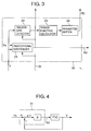
  • FIG. 3 is a block diagram showing a principal portion of the let-off control device of FIG. 2;
  • FIG. 4 is an equivalent block diagram of FIG. 3;
  • FIG. 5 is a diagram showing the operation of the let-off control device of FIG. 2;
  • FIG. 6 is a block diagram showing a principal portion of the let-off control device of FIG. 2 as an alternative configuration to the block diagram of FIG. 3;
  • FIG. 7 is a diagram showing the operation of the let-off control device of FIG. 2 incorporating the configuration of FIG. 6; and
  • FIG. 8 is a block diagram showing a let-off control device according to still another embodiment of the invention.
  • DETAILED DESCRIPTION OF THE PREFERRED EMBODIMENTS OF THE INVENTION
    Specific embodiments of the present invention are now described with reference to the accompanying drawings.
    Referring to FIG. 1, a let-off control device (hereinafter referred to simply as the control device) 10 of a weaving machine comprises as its principal elements a basic speed calculator 11, a controller 14, a control amplifier 17 and an average tension calculator 18. An output of the control device 10 is connected to a let-off motor M.
    The let-off motor M is connected to a warp beam WB via a reduction gear unit GD. Warp threads W fed from the warp beam WB are pulled out over a tension roller TR and separated into two sets of warp threads, upper warp threads W1 and lower warp threads W2, by a heddle which is not illustrated. The tension roller TR is associated with a detector LD, such as a load cell, which detects warp tension Y exerted on the tension roller TR on a real-time basis. The warp beam WB is associated with a winding diameter sensor DS which detects winding diameter D of (the warp W on) the warp beam WB.
    Weft density A of an in-process fabric, gear ratio m of the reduction gear unit GD, rotational speed N of the weaving machine and the winding diameter D fed from the winding diameter sensor DS are entered to the basic speed calculator 11, where the weft density A and the gear ratio m are set on an unillustrated setter while the rotational speed N of the weaving machine is output from an unillustrated rotational speed detector.
    An output of a target tension setter 12 is connected to the controller 14 via an summing point 13. Also, an output of the controller 14 is connected to the let-off motor M via a correction calculator 15, an summing point 16 and the control amplifier 17. Outputs of the average tension calculator 18 and the basic speed calculator 11 are connected to a subtracting terminal of the summing point 13 and to an adding terminal of the summing point 16, respectively. An output of a tachometer generator TG which is directly connected to the let-off motor M is fed back to the control amplifier 17. Further, a clock signal Sc is input from an unillustrated clock generator to the controller 14, and data on the winding diameter D output from the winding diameter sensor DS branches off and is entered to the correction calculator 15.
    A main shaft MS of the weaving machine is associated with a dog MS1, and a proximity switch DT is disposed face to face with the dog MS1. An output of the proximity switch DT is connected to the average tension calculator 18, to which the warp tension Y is entered from the detector LD.
    When the weaving machine is in steady-state running conditions, the basic speed calculator 11 calculates basic speed Vo (rpm) of the let-off motor M as follows: Vo = (25.4m/π)·N/(A·D) where the weft density A is expressed in picks per inch and π represents " a ratio of the circumference of a circle to its diameter".
    The proximity switch DT detects a specified crank angle  = o during each rotation of the main shaft MS and causes the average tension calculator 18 to operate. The average tension calculator 18 successively detects the warp tension Y at the specified crank angle o and obtains a moving average of the warp tension Y (= Y1, Y2 ....., Yn) for the n most recent rotations (n≧1) of the main shaft MS and then outputs average tension Ya = avg (Y1, Y2, ....., Yn) to the summing point 13, where n represents the number of rotations of the main shaft MS, Y1, Y2, ....., Yn indicate detected values of the warp tension Y at the crank angle o during the successive rotations of the main shaft MS, and avg (Y1, Y2, ....., Yn) is the average of the individual values of the warp tension Y (= Y1, Y2, ....., Yn). Thus, a signal corresponding to a deviation, "ΔYa = Yo - Ya (subtracting Ya entered from the average tension calculator 18 from a target tension Yo fed from the target tension setter 12)" is input to the summing point 13, and then the signal corresponding to the deviation Δya is output to the controller 14.
    The controller 14 has control elements for performing proportional, integral and differential (control) actions, for instance. It operates in synchronism with a specific operating cycle according to the clock signal Sc and thereby calculates speed correction value Vc based on the deviation ΔYa. The controller 14 performs sampling control operation according to the clock signal Sc, wherein control parameters of the individual control elements, such as proportional gain, integration time constant (integral gain) and differentiation time constant (differential gain), are optimally set with respect to maximum winding diameter Do of the warp W on the warp beam WB.
    The correction calculator 15 adjusts the speed correction value Vc fed from the controller 14 to speed correction value Vc1 based on the winding diameter D of the warp W on the warp beam WB as follows: Vc1 = Vc(D/Do)
    A signal corresponding to a summation, "Vo + Vc1 (a summation of a basic speed Vo fed from the basic speed calculator 11 and a speed correction value Vc1 fed from the correction calculator 15)" is input to a summing point 16 and then a signal corresponding to the summation value is output to the control amplifier 17.
    The summing point 16 and the control amplifier 17 controls the speed of the let-off motor M based on the basic speed Vo fed from the basic speed calculator 11 and the speed correction value Vc1 fed from the correction calculator 15, whereby the warp beam WB can be controllably driven such that the average tension Ya equals the target tension Yo (Ya = Yo). In this control operation, the tachometer generator TG detects rotational speed Vm of the let-off motor M and feeds it back to the control amplifier 17, thereby constituting a speed minor loop.
    The average tension calculator 18 is caused to operate once every rotation of the main shaft MS through the dog MS1 and the proximity switch DT. On the other hand, the controller 14 operates in synchronism with the operating cycle determined by the clock signal Sc which is generated at fixed rate, independently of the operating cycle of the average tension calculator 18. Therefore, there is not any likelihood that the substantial control parameters will fluctuate due to variations in the rotational speed N of the weaving machine. Here, it is preferable that pulse frequency of the clock signal Sc be determined such that the operating cycle of the controller 14 becomes smaller than the operating cycle of the average tension calculator 18 which is determined by the rotational speed N of the weaving machine.
    Other Embodiments
    The control device 10 of FIG. 1 may further comprises a switching circuit 19 and an automatic tuning circuit 20 as shown in FIGS. 2 and 3.
    The switching circuit 19 is inserted between the correction calculator 15 and the summing point 16. A tuning command St is entered from an unillustrated weaving machine control circuit. This tuning command St is further delivered to the automatic tuning circuit 20 and to the correction calculator 15 and the switching circuit 19 through the automatic tuning circuit 20.
    The aforementioned warp tension Y and simulated target tension Ys fed from an unillustrated step signal generator are entered to a proportional controller 21 of the automatic tuning circuit 20, and an output signal of the proportional controller 21 is entered to another adding terminal of the summing point 16 as a driving signal Sd. The warp tension Y branches off and is entered to a tension data detector 22 of the automatic tuning circuit 20 as well, and an output of the tension data detector 22 is connected to the controller 14 of the control device 10 via a transfer function calculator 23 and a parameter setter 24. The tuning command St branches off and is entered to the proportional controller 21 and the tension data detector 22 as well.
    If the tuning command St occurs when the weaving machine is at rest, the switching circuit 19 disconnects the summing point 16 from the correction calculator 15 and substantially disables the controller 14 as a consequence. At this time, the proportional controller 21 can drive the let-off motor M by outputting the driving signal Sd based on deviation ΔY (= Ys - Y) of the warp tension Y with respect to the simulated target tension Ys, and the tension data detector 22 can detect variations with time of the warp tension Y caused by the driving signal Sd. Since the rotational speed N of the weaving machine is equal to zero (N = 0) at this point, the basic speed Vo fed from the basic speed calculator 11 is equal to zero (Vo = 0).
    The proportional controller 21 of this embodiment forms a direct feedback control system for a controlled system from the let-off motor M to the warp tension Y as shown in FIG. 4, in which g represents proportional gain, F(s) represents a transfer function of the controlled system, and s represents a Laplacian operator.
    Referring to FIG. 4, it is assumed here that the transfer function F(s) of the controlled system is expressed as follows: F(s) = β/(s2 + αs) = (1/s)(β/(s + α)) Then, transfer function G(s) from the simulated target tension Ys to the warp tension Y is G(s) = a1/(s2 + a1s + a2) where α and β are constants, a1 = α and a2 = βg.
    The state of warp tension Y versus time in response to the step response of the aforementioned automatic tuning circuit 20 is expressed in Fig. 5. From Fig. 5, it is clearly seen that the warp tension Y varies for time t≧T1, in which T1 is a delay time of the actual controlled system. When the steplike simulated target tension Ys is given at time t = 0, the warp tension Y rises from its initial value Y1 up to a peak value Ym during a rise time T2 after the delay time T1 and settles and remains at a final value Y2 thereafter. The proportional gain g of the proportional controller 21 is properly set such that the warp tension Y exhibits an apparent peak value Ym and the peak value Ym would not diverge.
    For time t≧0, the step response y(t) of the transfer function G(s), i.e., a transfer function y(t) which is converted into a time domain from a transfer function G(s) in response to a step response, is given by y(t) = 1 - (2e-(a1/2)ta21/2/R)cos Q where
  • R = (4a2 - a12)1/2
  • Q = Rt/2 - tan-1(a1/R)
  • Adapting the step response y(t) to a portion time t≧ T1 of the curve of FIG. 5, a1 and a2 are obtained as follows: a1 = 2ln((Ym - Y2)/Y2)/T2 = α a2 = (π2 + ln((Ym - Y2)/Y2))/T22 = βg where ln is a symbol for natural logarithm. It is then possible to determine the transfer function G(s) by substituting α = a1 β = a2/g
    Since the transfer function F(s) contains an integral element F1(s) (= D/s) which corresponds to a rotational system from the let-off motor M to the number of rotations of the warp beam WB, transfer function F2(s), which excludes the integral element, of a mechanical system is calculated from the number of rotations of the warp beam WB as follows: F2(s) = β/(s + α) = (β/α)(1/(1 + (1/α)s)) Transfer function Fo(s) of the actual controlled system can be expressed as a first-order lag of a time constant T associated with the delay time T1 as follows: Fo(s) = Ko e-sT1(1/(1 + Ts)) Then, from a comparison between the transfer functions F2(s) and Fo(s), Ko = β/α T = 1/α It is possible to determine the transfer function Fo(s) of the actual controlled system in the aforementioned fashion.
    When the transfer function Fo(s) of the actual controlled system has been determined as shown above, optimum control parameter PD of the controller 14 having the control elements for performing proportional, integral and differential (control) actions can be calculated as follows, for instance: Kp = (0.9 to 1.2)T/(Ko T1) Ti = (2.4 to 2)T1 Td = (0.2 to 0.42)T1 or Kp = (0.6 to 0.95)T/(Ko T1) Ti = (1 to 1.35)T1 Td = (0.5 to 0.47)T1 where Kp is the proportional gain, Ti is the integration time constant (integral gain) and Td is the differentiation time constant (differential gain). Of the above equations, (7a) to (7c) are for optimizing response to external disturbances while (8a) to (8c) are for optimizing response to a target value.
    When the tuning command St occurs and the switching circuit 19 disables the controller 14, the steplike simulated target tension Ys is applied to the proportional controller 21 at time t = 0 of FIG. 5, and the proportional controller 21 generates the driving signal Sd to be delivered to the let-off motor M. The tension data detector 22 collects data on variations with time of the warp tension Y caused by the driving signal Sd throughout the time period t≧0 and outputs the delay time T1, the peak value Ym of the warp tension Y and the final value Y2 to the transfer function calculator 23. The transfer function calculator 23 can determine the transfer function F(s) using equations (1) to (4) and further determine the transfer function Fo(s) using equations (5) and (6).
    On the other hand, the parameter setter 24 can calculate the optimum control parameter PD for the transfer function Fo(s) using equations (7a) to (7c) or (8a) to (8c) and update set it to the controller 14. The controller 14 is then caused to resume its operation by resetting the tuning command St and thereby closing the switching circuit 19. Here, the delay time T1 output from the tension data detector 22 is delivered up to the parameter setter 24.
    Since the optimum control parameter PD set in the aforementioned fashion is calculated for the controlled system containing the integral element F1(s) (= D/s), however, the speed correction value Vc output from the controller 14 is corrected by the correction calculator 15 according to the winding diameter D of the warp W on the warp beam WB. More specifically, referring to FIG. 2, the correction calculator 15 calculates the speed correction value Vc1 as follows, using the winding diameter D (=D1) at the point in time when the tuning command St occurs or when the controller 14 resumes the aforementioned corrective control operation after the tuning command St has been reset: Vc1 = Vc(D/D1)
    The automatic tuning circuit 20 may include a signal generator 25 and a regression analyzer 26 instead of the proportional controller 21 and the tension data detector 22 as shown in FIG. 6. The warp tension Y is entered to the regression analyzer 26 and an output of the signal generator 25 is delivered to the summing point 16 as a driving signal Sd for the let-off motor M. The output of the signal generator 25 branches off and is entered to the transfer function calculator 23 as well. The tuning command St branches off and is entered to the regression analyzer 26 and the signal generator 25, and an output of the regression analyzer 26 is delivered up to the transfer function calculator 23.
    Generally, when a steplike input of a specific level V (= V1) is given to a controlled system of transfer function F(s) = (1/s)(β/(s + α)) at time t = 0 for a specific time period τ, variation with time Y(t) of output Y is given by Y = B(αX1 - 1 + e-αX1 - (αX2 - 1 + e-αX2)) where
  • Y = Y(t)
  • X1 = t
  • X2 = t - τ
  • B = βV1/α2
  • and X2 is assumed to be equal to zero (X2 = 0) when X2<0. By performing nonlinear regression analysis on equation (9) above, it is possible to determine parameters α and B and, then, parameter β which is given by β = α2B/V1.
    When the transfer function F(s) has been determined as described above, the transfer function Fo(s) of the actual controlled system containing the delay time T1 can be determined from equations (5) and (6) and, then, the optimum control parameter PD of the controller 14 for the transfer function Fo(s) can be calculated from equations (7a) to (7c) or (8a) to (8c).
    Specifically, when the tuning command St occurs and the switching circuit 19 is opened, the signal generator 25 generates the driving signal Sd of the specific level V (= V1) for the specific time period τ at time t = 0 of FIG. 7. The regression analyzer 26 collects data on variations with time of the warp tension Y caused by the driving signal Sd and determines parameters α and B by performing regression analysis on a time-varying curve which varies from initial value Y3 of the warp tension Y to its final value Y4 during a period including the delay time T1 and time t = T1 to τ - T1. The regression analyzer 26 excludes the influence of the delay time T1 by substituting τ = τ - T1 in equation (9). In FIG. 7, a solid line shows an example of an actual time-varying curve of the warp tension Y and a broken line shows an example of plotting obtained from equation (9) by regression analysis of the time-varying curve. Also in FIG. 7, the level V1 of the driving signal Sd and signal length τ are properly set such that the let-off motor M turns the warp beam WB in its forward running direction and the warp tension Y smoothly varies from the initial value Y3 to the final value Y4 which is not equal to 0.
    Referring to FIG. 6, the transfer function calculator 23 can determine the parameter β using the parameters α and B fed from the regression analyzer 26 and the level V1 of the driving signal Sd fed from the signal generator 25 and then determine the transfer function Fo(s) of the actual controlled system containing the delay time T1 from equations (5) and (6), wherein the delay time T1 can be obtained from the regression analyzer 26 as part of the data on variations with time of the warp tension Y (FIG. 7). Therefore, the parameter setter 24 may calculate the optimum control parameter PD of the controller 14 and set it to the controller 14, and the controller 14 may resume its operation when the switching circuit 19 is closed by resetting the tuning command St in exactly the same way as described above.
    Although the tuning command St is generated by manual operation at the time of, such as, replacement of the warp beam, in the foregoing discussion, it may be produced by appropriate automatic means. For example, provision may be made to monitor one or more parameters, such as the winding diameter D of the warp W on the warp beam WB or the deviation ΔYa of the warp tension Y, which could influence let-off control operation, and when any of these parameters considerably varies with time, the tuning command St may be produced automatically generated based on a judgment that tuning operation needs to be performed again.
    In the block diagrams of FIGS. 1 and 2, a compensating circuit 31 may be inserted between the target tension setter 12 and the summing point 13 as shown in FIG. 8. The compensating circuit 31 forms a control system having two degrees of freedom together with the controller 14. Specifically, when response to external disturbances of the controller 14 is to be optimized by equations (7a) to (7c), for example, the compensating circuit 31 can improve response to the target tension Yo by incorporating control elements for performing proportional and differential (control) actions with the same proportional gain Kp and differentiation time constant Td as those of the controller 14 and also optimize response to a target value.
    Although the present invention has been fully described by way of example with reference to the accompanying drawings, it is to be understood that various changes and modifications will be apparent to those skilled in the art. Therefore, unless otherwise such changes and modifications depart from the scope of the present invention hereinafter defined, they should be construed as being included therein.

    Claims (7)

    1. A let-off control device (10) for a weaving machine, said let-off control device (10) comprising:
      a basic speed calculator (11) for calculating a basic speed (Vo) of a let-off motor (M);
      an average tension calculator (18) for calculating a moving average of warp tension (Y) detected at a specific crank angle (o) in one or more picks;
      a controller (14) for calculating a speed correction value (Vc) for the let-off motor (M) based on deviation (ΔYa) of average tension (Ya) fed from said average tension calculator (18) with respect to a target tension (Yo); and
      a control amplifier (17) for controlling the speed of the let-off motor (M) based on the basic speed (Vo) fed from said basic speed calculator (11) and the speed correction value (Vc) fed from said controller (14);
      wherein said controller (14) operates in synchronism with an operating cycle which is independent from that of said average tension calculator (18).
    2. A let-off control device (10) for a weaving machine according to claim 1, wherein said controller (14) operates in synchronism with the operating cycle which is shorter than the operating cycle of said average tension calculator (18).
    3. A let-off control device (10) for a weaving machine according to claim 1 or 2 further comprising a correction calculator (15) for adjusting the speed correction value (Vc) fed from said controller (14) based on the winding diameter (D) of warp beam (WB).
    4. A let-off control device (10) for a weaving machine according to any one of claims 1 to 3 further comprising:
      a switching circuit (19) which disables said controller (14) when a tuning command (St) is issued; and
      an automatic tuning circuit (20) which sets a control parameter of said controller (14) by producing the tuning (St) command.
    5. A let-off control device (10) for a weaving machine according to claim 4, wherein said automatic tuning circuit (20) includes:
      a proportional controller (21) which generates a driving signal (Sd) to be delivered to the let-off motor (M) based on the deviation (ΔYa) of the warp tension (Y) with respect to the target tension (Yo); and
      a tension data detector (22) which detects variations in the warp tension (Y) caused by the driving signal (Sd) fed from said proportional controller (21).
    6. A let-off control devie (10) for a weaving machine according to claim 4, wherein said automatic tuning circuit (20) includes:
      a signal generator (25) which generates a driving signal (Sd) to be delivered to the let-off motor (M); and
      a regression analyzer (26)which performs regression analysis of variations in the warp tension (Y) caused by the driving signal (Sd) fed from said signal generator (25).
    7. A let-off control device (10) for a weaving machine according to one of claims 1 to 6 further comprising a compensating circuit (31) for improving response to the target tension (Yo).
    EP00120680A 1999-10-07 2000-09-21 A let-off control device for a weaving machine Withdrawn EP1091032A3 (en)

    Applications Claiming Priority (2)

    Application Number Priority Date Filing Date Title
    JP28743299A JP3542748B2 (en) 1999-10-07 1999-10-07 Loom delivery control device
    JP28743299 1999-10-07

    Publications (2)

    Publication Number Publication Date
    EP1091032A2 true EP1091032A2 (en) 2001-04-11
    EP1091032A3 EP1091032A3 (en) 2003-10-01

    Family

    ID=17717252

    Family Applications (1)

    Application Number Title Priority Date Filing Date
    EP00120680A Withdrawn EP1091032A3 (en) 1999-10-07 2000-09-21 A let-off control device for a weaving machine

    Country Status (2)

    Country Link
    EP (1) EP1091032A3 (en)
    JP (1) JP3542748B2 (en)

    Cited By (1)

    * Cited by examiner, † Cited by third party
    Publication number Priority date Publication date Assignee Title
    WO2023147168A3 (en) * 2022-01-31 2023-09-14 Unspun, Inc Manufacturing woven textile products on demand

    Families Citing this family (2)

    * Cited by examiner, † Cited by third party
    Publication number Priority date Publication date Assignee Title
    JP4098150B2 (en) * 2003-05-09 2008-06-11 津田駒工業株式会社 Weaving step prevention device for loom
    JP4851495B2 (en) * 2008-06-06 2012-01-11 津田駒工業株式会社 Loom warp control device

    Family Cites Families (4)

    * Cited by examiner, † Cited by third party
    Publication number Priority date Publication date Assignee Title
    CH654351A5 (en) * 1981-12-17 1986-02-14 Regatron Ag Method for regulating the warp tension in a weaving machine and warp let-off device for carrying out the method
    JPS60155757A (en) * 1984-01-20 1985-08-15 津田駒工業株式会社 Method and apparatus for electromotive feed-out and wind-up control of loom
    JPH0726283B2 (en) * 1987-11-28 1995-03-22 株式会社豊田中央研究所 Weft density control device
    JP2894709B2 (en) * 1988-12-28 1999-05-24 株式会社豊田中央研究所 Warp speed controller

    Cited By (1)

    * Cited by examiner, † Cited by third party
    Publication number Priority date Publication date Assignee Title
    WO2023147168A3 (en) * 2022-01-31 2023-09-14 Unspun, Inc Manufacturing woven textile products on demand

    Also Published As

    Publication number Publication date
    JP2001115364A (en) 2001-04-24
    JP3542748B2 (en) 2004-07-14
    EP1091032A3 (en) 2003-10-01

    Similar Documents

    Publication Publication Date Title
    EP0141372B1 (en) Method and apparatus for controlling variable-speed hydraulic power generaton system
    US4884597A (en) Pile warp yarn tension control
    US5331541A (en) PiD control unit
    EP1091032A2 (en) A let-off control device for a weaving machine
    EP1314806B1 (en) A control method and system for weft-braking devices for automatically adjusting the mechanical tension of the yarn in weaving maschines
    KR100535720B1 (en) Filling Bar Preventing Method and Apparatus
    US5101867A (en) Picking control for air jet loom with timing and pressure correction
    JP2530123B2 (en) Change weave control method
    JP3406823B2 (en) Loom delivery control device
    JP5366102B2 (en) Loom warp control method
    JP2002538323A (en) How to monitor the running / stopped state of the weft
    JP3541851B2 (en) Loom delivery control device
    JP2590469B2 (en) Stirling engine speed control device
    JPH0610241A (en) Method for controlling letting off
    JP2715113B2 (en) Optimal control method of loom speed
    JP3097021B2 (en) Warp tension controller
    JP2796366B2 (en) Loom weft insertion control device
    JP2670808B2 (en) Control device for drum type weft measuring and storing device
    US20020195160A1 (en) Method and apparatus for the regulation of the warp let-off a weaving machine
    JP2005261070A (en) Distributed power controller
    JP3046474B2 (en) Warp control device of loom
    JP2849410B2 (en) Loom weft insertion control device
    JPH0633540B2 (en) Weft insertion control device for jet loom
    JP4849659B2 (en) Loom warp control method
    JP2832854B2 (en) Loom fixed position stop device

    Legal Events

    Date Code Title Description
    PUAI Public reference made under article 153(3) epc to a published international application that has entered the european phase

    Free format text: ORIGINAL CODE: 0009012

    AK Designated contracting states

    Kind code of ref document: A2

    Designated state(s): AT BE CH CY DE DK ES FI FR GB GR IE IT LI LU MC NL PT SE

    AX Request for extension of the european patent

    Free format text: AL;LT;LV;MK;RO;SI

    PUAL Search report despatched

    Free format text: ORIGINAL CODE: 0009013

    AK Designated contracting states

    Kind code of ref document: A3

    Designated state(s): AT BE CH CY DE DK ES FI FR GB GR IE IT LI LU MC NL PT SE

    AX Request for extension of the european patent

    Extension state: AL LT LV MK RO SI

    AKX Designation fees paid
    REG Reference to a national code

    Ref country code: DE

    Ref legal event code: 8566

    STAA Information on the status of an ep patent application or granted ep patent

    Free format text: STATUS: THE APPLICATION IS DEEMED TO BE WITHDRAWN

    18D Application deemed to be withdrawn

    Effective date: 20040402